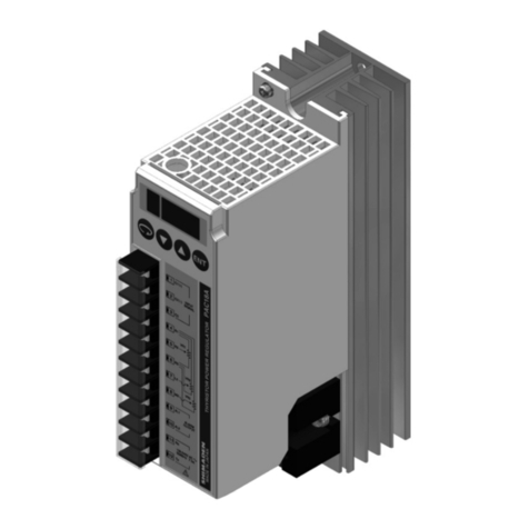
AUMA PF-M25 Series Manual

PROFOX actuators
PF-M25(X) –PF-M100(X)
PF-Q80(X) –PF-Q600(X)
Profibus DP
Use short instructions in combination with operation instructions only!
These short instructions are only complete with the respective operation instructions of the
actuator.Safety and warning instructions contained in the actuator operation instructions must
be heeded when performing work on the actuator!
Fieldbus connectionShort instructions

Table of contents Page
31. Basic information on fieldbus connection...........................................................................
42. Cable connection...................................................................................................................
73. Connect fieldbus cables........................................................................................................
94. Parameter (Profibus DP)........................................................................................................
105. Technical data......................................................................................................................... 105.1. PROFOX Profibus DP
2
Table of contents

1. Basic information on fieldbus connection
Electrical connection The actuator cover must be opened to allow connection of the fieldbus cables.
Refer to actuator operation instructions, “Electrical connection”chapter.
The “Electrical connection”chapter of the operation instructions fully applies
to the connection of the fieldbus cables.It is imperative to heed the safety and
warning instructions of this chapter in particular.
Fieldbus cable Table 1:
Cable recommendation
Only cables complying with IEC 61158 or IEC 61784, cable type A, may be used for Profibus DP wiring.
135to 165Ohm, ata measurementfrequency between3and 20MHzImpedance
< 30 pF per metreCable capacity
> 0.64 mmWire diameter
> 0.34 mm², corresponds to AWG 22Cross section
< 110 Ohm per kmLoop resistance
CU shielding braid or shielding braid and shielding foilScreening
Prior to installation, please note:
●Connect maximum 32 devices to one segment.
●If more devices are to be connected:
- Allot devices to different segments.
- Connect segments using repeaters.
●Install fieldbus cables at a distance of minimum 20 cm to other cables.
●If possible, fieldbus cables should be laid in a separate, conductive, and earthed
cable tray.
●Ensure absence of equipotential earth bonding differences between the indi-
vidual devices at fieldbus (perform an equipotential earth bonding).
1,500500187.5≥93.75Baud rate [kbit/s]
2004001,0001,200Maximum segment length [m]
3
Basic information on fieldbus connection

2. Cable connection
Cable arrangement
Cable arrangement depends on the number of cables connected in addition to the
mains cable.There are two options:
Figure 1: Cable arrangement
[1] Cable arrangement for one mains cable and one fieldbus cable
[2] Cable arrangement for a mains cable, a fieldbus cable and a signal cable
For better accessibility, we recommend heeding the following order.
1. If a signal cable is connected in addition to the fieldbus cable:Insert signal cable
into cable gland on the right and push upward until the cable is visible.
2. Insert fieldbus cables through middle cable gland and push upward until the
cable is visible.
3. Insert mains cable into cable gland on the left and also push upward until the
cable is visible.
4. Remove cable sheathing.
5. Strip wires.
→Controls approx. 6 mm, power supply unit approx. 10 mm
6. For flexible cables:Use wire end sleeves according to DIN 46228.
4
Cable connection

Protective earth connection
In case of a fault, electric shock due to presence of hazardous voltage if the
PE conductor is NOT connected!
Risk of death or serious injury!
→Connect all protective earth conductors.
→Connect PE connection to external protective earth conductor of connecting
cables.
→Start running the device only after having connected the protective earth con-
ductor.
7. Fasten PE using spade lugs or wire end sleeves at protective earth connection
( ) as shown.Do not completely loosen screw!
Figure 2: Protective earth connection (example)
Table 2:
Terminal cross sections and tightening torques of PE connection
Tightening torquesTerminal cross sectionsDesignation
3 –4 NmStandard version:1.0 –6 mm2(flexible)
via spade lug or wire end sleeve
Explosion-proof version:1.0 –2.5 mm2
(flexible) via spade lug or wire end sleeve
1.5 –2.5 mm2(flexible) directly
Standard version:1.5 –6 mm2(rigid)
directly
Explosion-proof version:1.5 –2.5 mm2
(rigid) directly
Protective earth connection (PE)
Connection of mains and signal cables
8. Connect mains cable according to order-related wiring diagram.
Table 3:
Terminal cross sections
Cross sectionWire typeDesignation
max [mm²]min [mm²]
2.50.08rigid/flexibleMains cable
AWG 12AWG 28AWG
5
Cable connection

9. Connect signal cables in push-in technology according to order-related wiring
diagram.
Information: Only required if a signal cable is to be connected in addition to
the fieldbus cable.
Damage to push-in terminals by jamming of wire end sleeves with the housing!
Replacement of the complete component is required.
→Use wire end sleeves with smooth surface.
→Always press the push-in terminals completely down using a screwdriver and
always carefully remove signal cables.
→It must be possible to pull out the signal cable without resistance when the push-
in terminal held down.
Information: To avoid unevenness at wire end sleeve, AUMA recommends
using the Crimpfox 6 model by Phoenix Contact as suitable crimping pliers.
Figure 3: Connect signal cables
Table 4:
Terminal cross sections
Cross sectionWire typeDesignation
max [mm²]min [mm²]
1.50.2solidI/O signal cable
1.50.2flexible
1.50.2flexible with wire end
sleeve without plastic
sleeve
AWG 16AWG 24AWG
10. Connect fieldbus cables.
Refer to subsequent chapter!
6
Cable connection

3. Connect fieldbus cables
If a PROFOX actuator is part of a complete line or loop topology,the connexion
remains continuous even if the actuator is without power or defective.
1. Observe characteristics of topology used.
Figure 4: Structure for line topology
further fieldbus devices will follow□
last fieldbus device, termination must be activ-
ated
■
from the previous device↑
to the next device↓
In case of a fault, electric shock due to presence of hazardous voltage if the
PE conductor is NOT connected!
Risk of death or serious injury!
→Connect all protective earth conductors.
→Connect PE connection to external protective earth conductor of connecting
cables.
→Start running the device only after having connected the protective earth con-
ductor.
2. Strip fieldbus cables.
7
Connect fieldbus cables

Shield connection 3. Remove fieldbus cable shield at a short section as shown and connect to shield
connection. Ensure absence of electrical contact to the terminal.
Information: If the cables are too thin to be clamped, fold over the shielding
and clamp it underneath.
Information: Strain relieve must always be made via cable glands.For this,
the shielding connection may not be used.
Figure 5: Shield connection
Fieldbus cables 4. Connect fieldbus cables:Connect green wires with green terminal and red wires
with red terminal.
Table 5:
Terminal cross sections
Cross sectionWire typeDesignation
max. [mm²]min. [mm²]
1.50.5solidFieldbus cables
1.50.5flexible
1.00.5flexible with wire end
sleeve without plastic
sleeve
AWG 16AWG 20AWG
Bus termination 5. If the actuator is the last fieldbus device within the fieldbus segment:Activate
parameteror functionPRM_5559 Bus termination channel 1 via AUMAAssistant
App or AUMA CDT software.
Information: As soon as the bus termination is active, the connection to the
next fieldbus device is automatically interrupted to avoid multiple terminations.
The bus termination is deactivated when leaving the factory.
6. If the PE conductor has been removed from the cover, it must be tightened
applying 2.2 Nm tightening torque prior to re-placing the cover.
7. Fasten cable glands with the torque as specified by the manufacturer to ensure
respect of required enclosure protection.
8. Connect power supply.
If the end position setting is carried out with the internal operation buttons
following the connection to the power supply: Do not close cover!
8
Connect fieldbus cables

4. Parameter (Profibus DP)
Signals
Feedback signals via fieldbus are defined by the GSD file.
Information If required, download the GSD file (General Station Description) from the Internet:
www.auma.com
Refer to Technical data of the actuator for the Profibus DP ident no.
Fieldbus address (Slave address)
Via AUMA Assistant App or AUMA CDT software:
DIS_53 Configuration
DIS_600 Profibus
PRM_1321 DP1 slave address
Default value: 126
Setting range: 0 ... 126
For information on the feedback signals via fieldbus and the configuration of the
parameters via fieldbus interface, refer to Manual “PROFOX Device integration
Profibus DP”.
Information Profibus DP address setting is carried out via parameter (AUMA CDT software or
AUMA Assistant App)
Change-over between fieldbus control and OPEN-CLOSE via I/O signals (for
actuators with fieldbus interface)
As standard, the actuator is supplied with fieldbus and binary signals.A digital input
is used to define which source is active, this means whether the actuator is controlled
via fieldbus or via I/O signals. It is not possible to use both sources to active
simultaneously.The PRM_926 Signal DIN 3 signal is assigned to PZD_275 I/O
interface as factory setting:
Not live (= 0V) means that control is made from REMOTE via fieldbus.
Live (= 24V) means that control is made from REMOTE via binary I/O signals.
Commands for the operation function:
OPEN-CLOSE operation commands can be issued via fieldbus or a setpoint can be
sent for any position.Change-over is made via the PZD_332 Fieldbus SETPOINT
command.
●Setpoint control:
Fieldbus SETPOINT command bit = 1 = REMOTE SETPOINT
The actuator reacts to the setpoint E1 transmitted via the fieldbus.
●OPEN-CLOSE control:
Fieldbus SETPOINT command bit = 0 = REMOTE OPEN-CLOSE
Actuator can be operated via Fieldbus OPEN/Fieldbus CLOSE command bits
in direction OPEN or CLOSE.
For further information on these parameters as well as on other settings,refer
to the Manual PROFOX “Parameters and functions”.
9
Parameter (Profibus DP)

5. Technical data
Information The following tables include standard and optional features.For detailed information
on the customer-specific version, refer to the order-related data sheet.The technical
data sheet can be downloaded from the Internet in both German and English at ht-
tp://www.auma.com (please state the order number).
5.1. PROFOX Profibus DP
Setting/programming the Profibus DP interface
Automatic baud rate recognitionBaud rate setting
The setting of the Profibus DP address is made via parameters using the AUMA Software CDT or AUMA
Assistant App.
Setting the Profibus DP interface
Commands and signals of the Profibus DP interface
OPEN, STOP, CLOSE, position setpoint, RESET, EMERGENCY operation commandProcess representation output
(command signals)
●End positions OPEN, CLOSED
●Actual position value
●Selector in position LOCAL/REMOTE/OFF
●Torque switches OPEN, CLOSED
●Limit switches OPEN, CLOSE
Process representation input
(feedback signals)
●Torque switch tripped in mid-travelProcess representation input
(fault signal)
The behaviour of the actuator is programmable:
●Stop at current position
●Execute operation to end positions OPEN and CLOSED
●Travel to any intermediate position
●Execute last received operation command
Behaviouron lossof communication
General Profibus DP interface data
Profibus DP according to IEC 61158 and IEC 61784-1Communication protocol
Line (fieldbus) structure.When using repeaters, tree structures can also be implemented. If a unit fails,
communication in the line is still maintained.
Network topology
Twisted, screened copper cable according to IEC 61158Transmission medium
EIA-485 (RS485)Fieldbus interface
●Baud rate and maximum cable length (segment length) without repeater:
-between 9.6 and 93.75 kbit/s: 1,200 m
-for 187.5 kbit/s:1,000 m
-for 500 kbit/s:400 m
-for 1,500 kbit/s:200 m
●Baud rate and possible cable length with repeater (total network cable length):
-between 9.6 and 93.75 kbit/s: approx. 10 km
-for 187.5 kbit/s:approx.10 km
-for 500 kbit/s:approx.4 km
-for 1,500 kbit/s:approx.2 km
Transmission rate/cable length
●DP master class 1, e.g.central controllers such as PLC, PC,.
●DP master class 2, e.g.parts programming/configuration tools
●DP slave, e.g. devices with digital and/or analogue inputs/outputs such as actuators, sensors
Device type
32 devices without repeater, with repeater expandable to 126Number of devices
●Token-passing between masters and polling for slaves
●Mono-master or multi-master systems are possible.
Bus access
Cyclic data exchange, sync mode, freeze mode, fail safe modeSupported fieldbus functions
0x1146. Standard applications with Profibus DP-V0 and DP-V1Profibus DP ident no.
10
Technical data

11

AUMA Riester GmbH & Co. KG
P.O. Box 1362
DE 79373 Muellheim
Tel +49 7631 809 - 0
Fax +49 7631 809 - 1250
www.auma.com
Y009.651/003/en/1.22
For detailed information on AUMA products, refer to the Internet: www.auma.com
This manual suits for next models
11
Table of contents
Other AUMA Controllers manuals
AUMA
AUMA SG 05.1-FA07 User manual
AUMA
AUMA SA 25.1 User manual

AUMA
AUMA SAN 07.1 User manual
AUMA
AUMA SAI 07.2 User manual
AUMA
AUMA SAEx 07.2 User manual
AUMA
AUMA SGM Series User manual
AUMA
AUMA SQ 05.2 User manual
AUMA
AUMA PROFOX PF-Q80 User manual
AUMA
AUMA AMB 01.1 User manual

AUMA
AUMA SAExC Series User manual
AUMA
AUMA NORM SQ 05.2 Administrator Guide
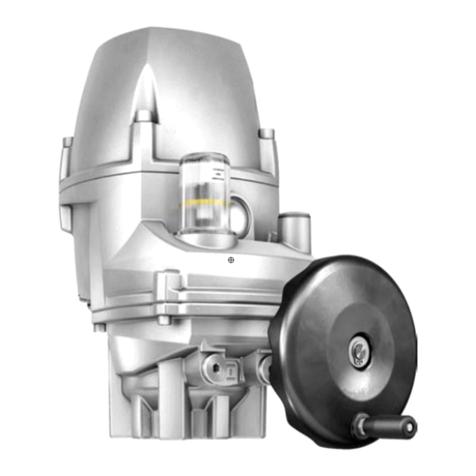
AUMA
AUMA PROFOX PF-M25 User manual
AUMA
AUMA SAVEx 07.2 User manual
AUMA
AUMA AM 01.1 Manual
AUMA
AUMA SQVEx 05.2 User manual
AUMA
AUMA SAVEx Series User manual
AUMA
AUMA SA 48.1 User manual

AUMA
AUMA SAEx 07.2 User manual
AUMA
AUMA SG 03.3 User manual
AUMA
AUMA SG 05.1-F05 User manual
