Franco Belges Le Continental 174 07 53 User manual

Technical manual
to be saved
by the user
for future reference
Document n° 952-3 EN ~ 02/03/2000
Les Fonderies Franco-Belges
59660 MERVILLE
Phone : 03.28.43.43.43
Fax : 03.28.43.43.99
RC Hazebrouck 445750565B
Subject to modifications
Le Continental
Oil fired stove
Model 174 07 53
(ANSI/UL & CAN/CSA approved)
Français
English
Description of the appliance
Installation instructions
Operating instructions
Spare parts
Warranty certificate
Norsk

Descriptionoftheunit ........................................3
Description...................3
Optionalequipment..............3
Specifications.................3
Operatingprinciple..............4
Installationinstructions .......................................4
Positionoftheunit ..............4
Chimney....................4
Chimneyconnector..............4
Connection to a L.VENT chimney ......4
Pre-utilisation check .............5
Mounting the levelling feet ..........5
Levelling ....................5
Externaltank .................5
Oilflowadjustment..............6
Chimneydraught ...............6
Maintenance of the Chimney .........6
Operatinginstructions........................................6
Fuel ......................6
Lighting procedure ..............6
Operatingprocedure .............7
Shuttingdown.................7
Recommendation...............7
Maintenance of the stove ..........7
Troubleshooting ...............8
Spareparts...............................................9
CONTENTS Page Page
FRANCO BELGE congratulates you on your choice.
FRANCO BELGE, which has been granted the ISO 9001 certification, guarantees the quality of its
appliances and is committed to meet its customers’ needs.
FRANCO BELGE, which can boast a 75-year experience in the industry of heating devices, uses
state-of-the-art technologies to design and manufacture its whole range of products.
This document contains instructions on how to install your appliance and and make full use of its
functions, both for your comfort and safety.
Document n° 952-3 EN ~ 02/03/2000
Continental Poêle à combustible liquide
2Notice de référence

1.Description of the unit
1.1. Description
Flued oil stove with vaporizing burner (Norm EN1)
1.2. Optional equipment
¤ Ground vat
1.3. Specifications
Nominal Heat Output (NF D 35.001) . . . kW 6,5
...................... Btu/hr 26.000
Oil consumption at :
- maximum speed . . . . . . . . . . . . . . l/h 0,81
.......................gal/hr 0,22
- minimum speed . . . . . . . . . . . . . . l/h 0,25
.......................gal/hr 0,066
Chimney draft required at :
- maximum speed . . . . . . . . . . . . . . Pa 15
- minimum speed . . . . . . . . . . . . . . Pa 6
Weight.................... kg 55
USA/CANADA - Connection to a L.VENT chimney :
Nominal heat output . . . . . . . . . . . Btu/h 19 600
........................kW 5.75
Oil consumption at nominal speed . USgal/h 0.198
........................ l/h 0.75
Chimneydraft.............. “w.c.g 0.06
........................ Pa 15
7
9
8
1
2
3
4
5
610
11
12
13
Fig. 1 - Description
1 - Cover
2-Topplate
3 - Flue baffle
4 - Flue box
5 - Draught regulator
6 - Carburettor
7 - Draught control
8 - Combustion chamber
9 - Main door
10 - Catalyser ring
11 - Catalyser cover
12 - Catalyser body
13 - Air inlet holes
540
460
Ø 120 /127
805
530
350
805 mm - 31 3/4"
Ø 120 / 127 mm - Ø 5"
540 mm - 21 1/4"
530 mm - 20 4/5"
350 mm - 13 3/4"
460 mm - 18"
Fig. 2 - Dimensions in mm
Document n° 952-3 EN ~ 02/03/2000
Continental Poêle à combustible liquide
Notice de référence 3

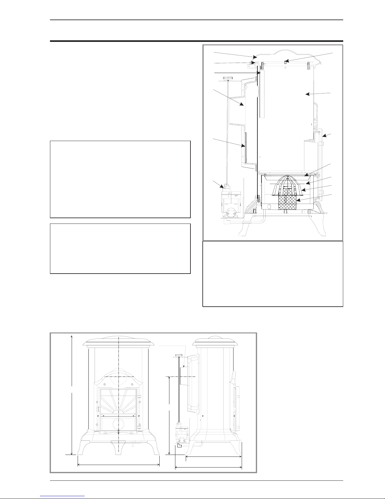
1.4. Operating principle
Furnace oil is fed to the burner floor (fig. 1) where is it
ignited by means of a firestarter. The heat produced by
this flame brings the burner temperature to the required
level to vaporize the fuel. Oil will only burn as a vapour
not a liquid.
Room combustion air enters the burner through the air
inlet holes (# 13, fig. 1).
In the center of the burner is the catalyser (# 12, fig. 1)
which aids in vaporizing the fuel. When the stove is
operation,the catalyserglows red.The stove should not
be used with out both the catalyser (# 12, fig. 1),
catalyser top (# 11) and ring (# 10).
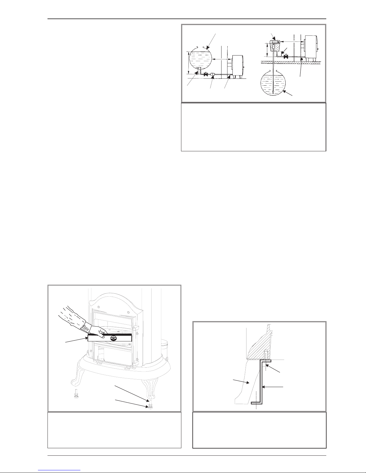
A de-scaling lever (# 1, fig.8) can be pushed and pulled
inandoutaswellasturningslightlyatthesametimeto
keep the inlet pipe clear of carbon buildup.
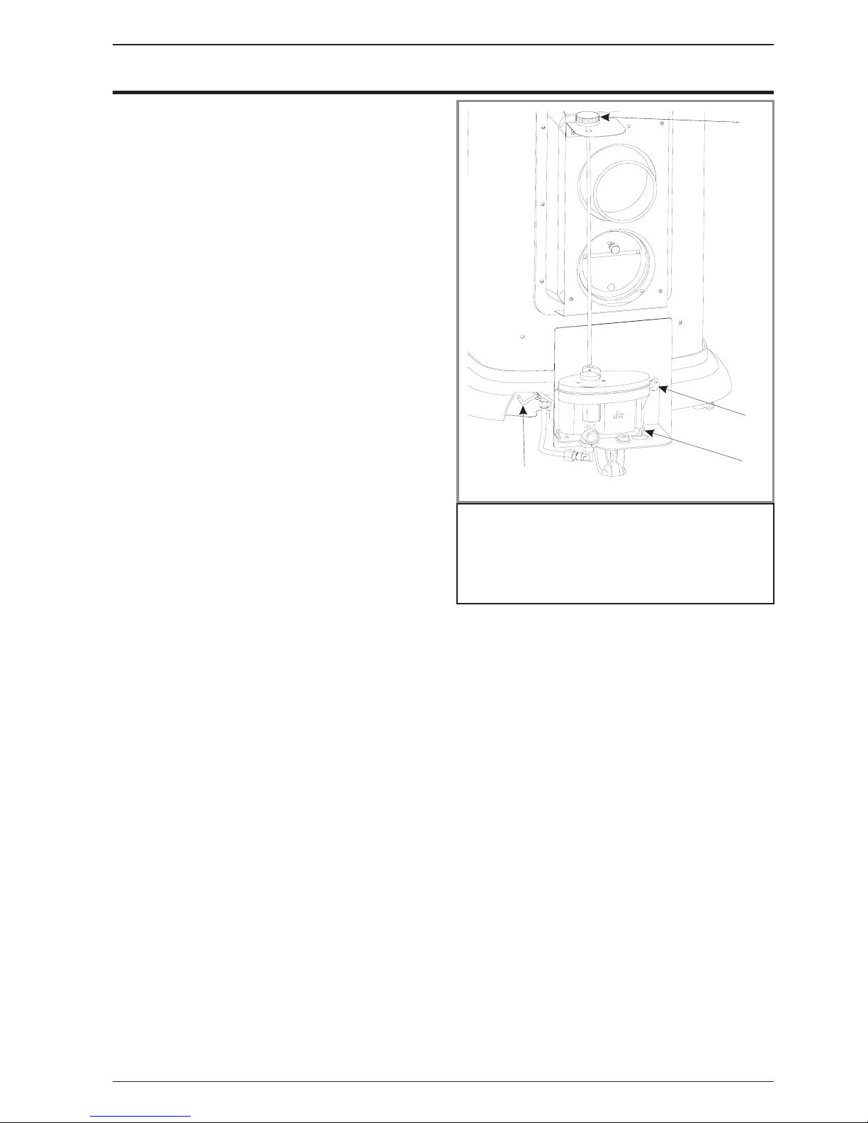
The stove float regulator contains a filter to trap
impurities.
A safety lever controls fuel flow. Oil can only enter the
float chamber when the safety lever is depressed.
Oil temperature variations will affect the oil flow into the
float chamber. A float in the chamber raises the fuel
level available to the burner.
The carburetor is also controlled by a control knob
which turns from “0" (off) to ”6" (high setting).
A draft regulator (# 3, fig. 7) ensures a constant air
intake to the burner regardless of external factors.
2.Installation instructions
USA / CANADA : The installation of this stove must com-
ply with state and local requirements and the standard
CSA B139.
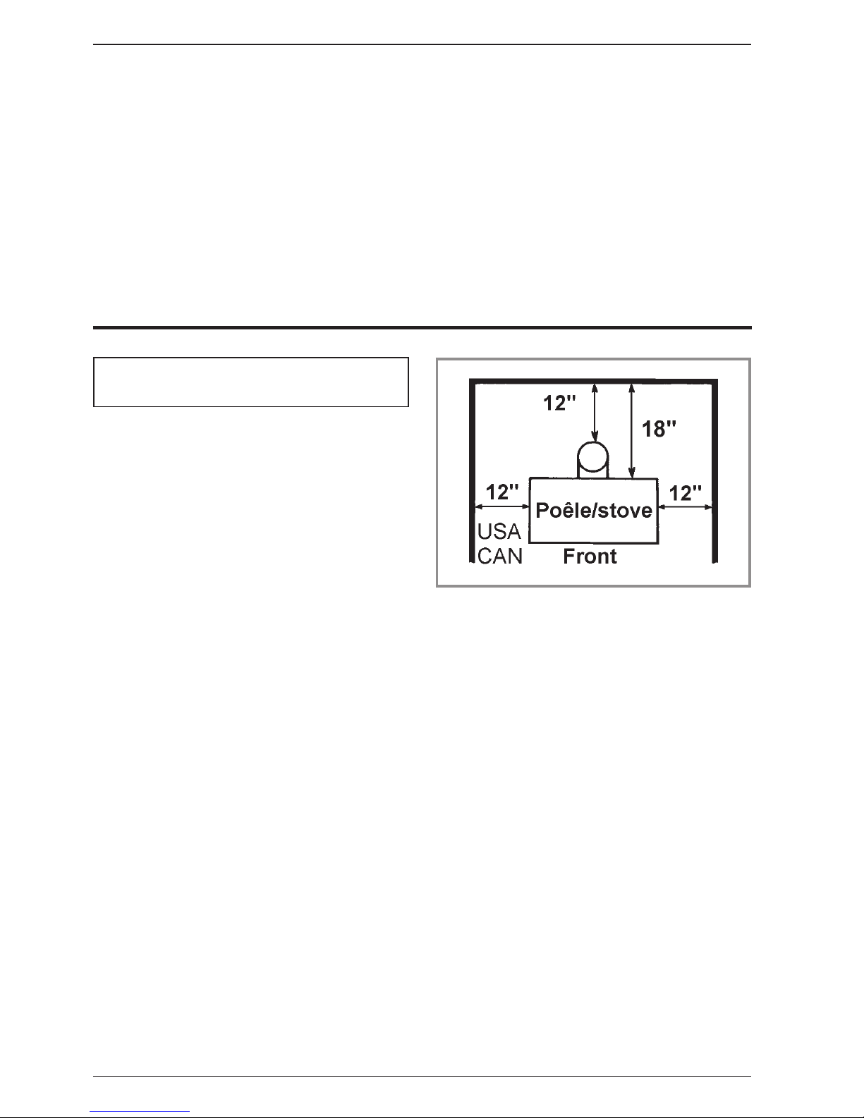
2.1. Position of the unit
- The position of the appliance must be chosen very
carefully in order to obtain the best possible results for
heat distribution.
- Position the unit to comply with the minimum
clearances to combustible material. Minimum
clearances are shown from the vertical portion of the
chimney connector. Check that no overhead cross
members in the ceiling will be cut. Reposition unit if
necessary, being careful not to move closer than the
minimum clearances.
- Outside air : For the oil stove to function properly, an
adequate supply of combustion air is required.
2.2. Chimney
- Ensure that the flue has sufficient draught (refer to
technical details).
- Minimum flue diameter, 10 cm (4" I.D).
- The chimney must be at least 4.5 m (15 ft high).
- The flue must not be shared with any other appliance.
- Downdraughts caused by obstacles close to the
chimney top may sometimes be prevented by fitting an
anti-downdraught cap to the top of the chimney.
- The chimney must have a constant cross section. Too
large a flue could affect the chimney draught.
- The chimney must be soundly constructed, in order to
prevent cold air infiltration.
- The flue must be well insulated, water and air tight. A
chimney with acold internal surface can prevent a good
chimney draught and condensation will occur.
-The flue must be swept at least once a year.
2.3. Chimney connector
- The appliance must be as close as possible to the
chimney. Avoid horizontal flue connection pipes which
can dangerously restrain functioning of the appliance.
The connector pipe should be standard black painted or
blued steel pipe of not less than 30 gage; 304 grade
stainless steel of not less than 30 gage; or 1 mm
viterous enamelled steel, with a maximum diameter of
5 inch O.D. - (127 mm). It is the installer’s responsability
to conform to local building standards and requirements
with regard to installation.
Single wall pipe may be utilized being careful to
maintain clearances to any combustible surface. (fig.3)
Once the stove has been properly installed the chimney
draught must be checked with a draught meter.
If the chimney draught is excessive or irregular, a
draught stabilizer (barometric damper) must be
installed to the connector pipe.
2.4. Connection to a L.VENT chimney
USA / Canada
: The 174 07 53 appliance is certified to
be connected to a 5" L.VENT chimney with its nominal
heat outputlimited to 19600 Btu/h (5.75 kw) .This willbe
achieved by replacing the float-regulator (carburator)
(# 19 fig. 9).Please contact your dealer to have this
alteration done.
WARNING. FRANCO-BELGE is not responsible for
any incidental or consequential damages if this
operation is not done.
Figure 3 - Minimum clearances to combustible surfaces
Document n° 952-3 EN ~ 02/03/2000
Continental Poêle à combustible liquide
4Notice de référence

2.5. Pre-utilisation check
Check, that the seals are in good condition, that the
door closes correctly, that the glasses are not
damaged.
2.6. Mounting the levelling feet
Fit the 3 screws and the 3 caps supplied (on the
burner) into each leg of the stove (fig. 4).
2.7. Levelling
It is essential to ensure that the appliance sits level
on the floor. Adjust the levelling feet. Use a spirit level
across the burner pot to check the level (fig. 4).
2.8. External tank
When the stove is connected to an external or remote
tank, it must be secured to the floor. The bracket is
included (fig. 6).
A barometric fuel tank should not be positionned where
it will be in the direct rays of the sun or adjacent to a
source of intense heat.
If the tank is more than 8 ft (2,5 m) higher than the stove
a pressure reducer must be installed on the oil line (see
fig. # 5).
If the tank is lower than the stove a lift pump will have
to be utilized (see fig. # 5).
A clearance of 6 “ (15 cm) must be maintained between
the external/remote tank and the stove.
1
3
46
2
71
5
3
6
2
7
1
2
3
Figure 4 - Levelling
1 - Spirit level
2-Screw
3-Cap
Figure 5 - Oil supply
1-8ftmax.
2 - At least 9,5 in.
3-OilTank
4 - Filter
5 - Suction pump with re-
serve
6-PipeØ3/8"O.D.
7 - 0,15m minimum
1
2
3
Figure 6 - Bracket
1 - Rear foot
2 - Bracket 3 - Foot fixation screw
Document n° 952-3 EN ~ 02/03/2000
Continental Poêle à combustible liquide
Notice de référence 5

2.9. Oil flow adjustment
The float regulator has been adjusted at the factory and
should not need further adjustment. If the burner does
not work correctly, check possible causes before
readjusting the settings :
- Chimney draught
- Fresh air inlet
- Oil supply.
Low setting (Refer to fig. 7 , # 2) :
- set the regulating knob on “1" and let the burner run
for a few minutes. The flame must completely cover the
bottom of the burner and the catalyser body must be
glowing red hot.
- if the flame is too small, the stove will soot up quickly
; increase the flame by turning the setting screw (# 2)
clockwise.
- if the flame is too high, reduce the flame by turning the
setting screw (# 2) counter clockwise.
High setting (Refer to Fig. 7 , # 1) :
- set the regulating knob on “6" and let the burner run
for a few moments. The flame must be shaped like a
cone and reach the upper part of the door.
- if the flame is too low, increase by turning the set
screw anti-clock-wise.
- if the flame is too high, reduce by turning the setscrew
clockwise.
Please note - Very important : The adjustments of the
float regulator are very sensitive. The hight and the low
setting screws must never be turned more than a 1/4 of
a turn at a time in any direction from their initial setting.
When making any adjustments, allow 3 to 5 minutes
between adjustments to allow burner to stabilize to
previous adjustment before proceeding, if necessary.
2.10. Chimney draught
Once the stove has been properly installed, the
chimney draught must be checked.
The adjustment of the draught will be made with the
barometric damper located at the back of the stove (# 3
of fig. n° 7).
The reading of the draught must be done once the unit
is hot (minimum 30 minutes of use).
Refer to the specifications p. 3 for minimum draught
requirement on mini setting and on maxi setting.
2.11. Maintenance of the Chimney
Chimney and chimney connector should be inspected
at least once every three months during the heating
season to determine if a soot build up has occurred. If
soot has accumulated, it should be removed to reduce
the risk of a chimney fire.
3
2
1
Figure 7 - Setting
1 - Adjustment screw for maximum setting
2 - Adjustment screw for minimum setting
3 - Adjustment of the draught regulator
Document n° 952-3 EN ~ 02/03/2000
Continental Poêle à combustible liquide
6Notice de référence

3.Operating instructions
3.1. Fuel
Warning
: Your stove is fitted with a specific float
regulator for a specific oil.
¤Fueloil#2orfueloil#1
The fuel oil must be free from any dirt and water which
could disturb the stove in operation.
3.2. Lighting procedure
- Be sure the control knob is to “0".
- Turn on oil supply,
- Push down gently on the safety lever (# 3 of fig. n° 8).
This will allow the oil to flow into the regulator.
- Open the front door, and remove the catalyser from
burner. Make sure the inside of the pot is clean
thoroughly, and there is no oil accumulation.
- Place 2 tablespoons of methylated spirit or gelled
alcohol in the bottom of the pot. Light the starter gel or
methylated spirit with a fireplace match or long butane
lighter. Place the catalyser back into the burner, being
sure it is centered in the burner. Shut the main door.
- Allow the catalyser to heat approximately 30 to 45
sec.. Turn dail to “1" position.
- Allow 10 to 15 minutes for oil fire and draught to
stabilize. The catalyser should glow red before
adjusting the control knob to a higher setting,
3.3. Operating procedure
• Allow 10 to 15 minutes after lighting to adjust the
control knob to a higher setting, usually between a “2"
and ”4" setting.
When increasing the heat output, move the control
knob only 1 number, allowing 5 minutes between moves
for the flame to re-adjust to new setting..
• If the burner stops during operating, immediatly turn
off the control knob (position “0") and wait until the
burner is completely cool before repeating the lighting
procedure.
3.4. Shutting down
- Set dial to the “0" position,
- Raise the safety lever of the regulator.
- Allow the flame to burn out completely before opening
the door.
3.5. Recommendation
• The adjustment of the stove has been made at the
factory and checked by your installer. Any anomaly of
operation should be reported to him at once.
• This room heater is a hight heat producing appliance
and may cause severe burns if touched on the glass
front door, or on top directly over the burner - keep
children away - Do not use for drying wet clothing.
CAUTION : Never light the burner if there is oil in the
burner pot. Clean out oil before lighting.
Racing : An audible fluttering sound is an indication
that there is too much oil in the pot burner and/or a lack
adequate draught.
- turn off oil supply and set the control knob in closed
position -0-, until fire has decreased to proper burn rate.
•Do not overfire : If the stove or chimney connector
starts to glow, you are overfiring.
3.6. Maintenance of the stove
•Every week : operate the de scaling lever (# 3 of
fig. 8) :
- Pull the rod, then push the rod in rotating 360 degrees
two or three times (CAUTION : The rod is HOT).
•Every 3 or 4 months : Clean the burner completely.
- Remove all the parts of the catalyser (# 10, 11, 12 of
fig. 1).
- Using a soft bristle brush (a small clean paint brush),
carefully brush off the catalyser. Loosen any carbon
soot from the bottomof the burner with a putty knife, and
vacuum clean. Ensure that the small air holes in burner
are free of carbon.
•At least once a year / End of heating season : Clean
or replace all the oil filters in the oil supply line.
To clean the filter of the float regulator
:
- set the regulation knob in closed position “0",
- turn off the tankvalve or the valve of the oil supply line,
- raise the safety lever of the float regulator,
- place a small container (or a small rag) under the
2
3
4
1
Figure 8 - Operating devices
1 - De-scaling lever
2 - Regulation knob
3 - Safety lever
4 - Access to regulator fil-
ter
Document n° 952-3 EN ~ 02/03/2000
Continental Poêle à combustible liquide
Notice de référence 7

regulator filter opening in order to collect the oil
contained in the regulator,
- remove the filter cover plate located under the
regulator (# 4 of fig. 8) with a screwdriver,
- remove the tubular filter from the regulator. Clean, if ne
it with oil using a soft brush, never a wire-brush,
- replace the filter in the regulator, install the cover plate
and secure with the screw.
• Clean all the enamelled panels of the stove with a dry
or slighly damp soft cloth.
•Useasoftcleanclothtowipethefrontglasswhenthe
unit is running at a low burning rate. When the main
door is opened for cleaning, the flame will be disturb,
and turn to a yellow flame. Clean quickly, but gently.
Close the door, the flame will return to a normal burning
position.
N.B. :The appearance of cracks when burning the
enamelled units is quite usual and tends to disappear
when the appliance is cooling down. It should not be
considered as a defect but rather as a patina of the
enamel which does not affect its quality nor its service
ability.
3.7. Trouble shooting
SYMPTOM PROBLEM −TEST SOLUTION
Flames extinguish during
lighting. ¤Verycoldchimney.Nodraft
established. −- Leave door ajar until fire has caught.
- Check air supply in the room.
Fire extinguishes once
firestarter has burnt off. ¤Fueltankisempty. −- Fill tank.
¤ Fuel valve is closed. −-Openvalve.
¤ Main regulator float not engaging. −- De-press the safety lever.
¤ Control knob is set on “0" −- Adjust control knob to ”1".
Fire extinguishes during use. ¤Fueltankisempty. −- Fill tank.
¤ Insufficiant draft.
þ
−- Call your installer.
Flame is excessely large,
smokey and sooty. ¤ Fuel adjustment made too quickly. −- Return control knob to “1"; wait for normal combustion.
(catalysershould glowred) Wait5to15minutesbetween
each adjustment.
Stove burns noisily,
extinguishes and relights itself. ¤ Burner contains excess fuel. −- Adjust to lower setting. If problem persists call your
installer.
¤ Insufficient fuel. −- Check that the de-scaler, the regulator filter and burner
pot are cleaned.
Fire smokes.Soot build up
noticed.Flame imbalance ¤ Insufficient air supply. −- Increasefresh airsupply(open door,window;addmake
up air supply).
¤ Downdraft or blockage in chimney.
þ
−- Check Chimney for Soot build up.clean if necessary.
- Ensure chimney height is sufficient and cap is not
affected by any nearby obstructions.
- Room is in negative pressure.Increase fresh air supply.
Check draft with draft meter and adjust if not to
requirements. See page 4.
¤ Oil flow is too low on 1 setting.
þ
−- Adjust low flow rate while control is set on “1", call your
installer.
¤ Stove is not level. Flame
imbalance. −- Check level.Adjust if necessary.
¤ Catalyser not centered. Uneven
fuel distribution resulting in
secondary air shortage.
−- Center catalyser assembly
¤ Insufficient fuel. −- Check that the de-scaler, the regulator filter and burner
pot are cleaned.
¤ The draft regulator is blocked in
open position
þ
−- Unlock the draft regulator.
- Check the regulator adjustment (p. 6) and refit, if
necessary.
Coke build up noticed. ¤ Excessive air supply. −- Adjust draft.
þ
: This sign means that you should
asked for a qualified engineer to do the
work.
Document n° 952-3 EN ~ 02/03/2000
Continental Poêle à combustible liquide
8Notice de référence

4.Spare parts
When ordering spare parts, please indicate : model n°,
colour code, description of the part, code of the part. Example : Oil fired stove 1740753L,leg300120 77
A= 174 07 53 L B= 174 07 53 Y C= 174 07 53 J
1 100917 Campin .........12x20M7.......A ......B.......C...... 01
2 905317 Basicburner ....................A ......B.......C...... 01
3 110105 Barometricdamper.................A ......B.......C...... 01
4 110404 Hingepin.......... 6x30........A ......B.......C......04
5 111275 Elbow, ring, nut ...................A ......B.......C...... 02
6 119216 Descaler ......................A ......B.......C......01
14 142301 Adhesiverope ...................A ......B.......C.....0,76m
15 142764 Gasket .......................A ......B.......C......01
16 149868 Knob ........................A ......B.......C...... 01
17 161025 Touch-uppaint........(L).........A .....................01
17161027 Touch-uppaint........(J).........................C......01
18 162534 Descriptiveplate..................A ......B.......C...... 01
19 165140 Floatregulator...................A ......B.......C...... 01
20 134601 Pin ............. 2x20........A ......B.......C......01
22 179605 Regulator shaft ...................A ......B.......C...... 01
24 181602 Ceramicrope.........Ø8 ........A ......B.......C.....0,70m
25 181614 Ceramicrope........d.9,5........A ......B.......C.....0,85m
26 188789 Refractoryglass ... 11x(160x20x3) .....A ......B.......C......01
26 199306 Refractoryglass ....1x(160x20x3)......A ......B.......C...... 11
27 189104 Screw............ 6x22........A ......B.......C...... 01
28 189118 Screw............ d.10........A ......B.......C...... 01
34 208410 Heat shield .....................A ......B.......C...... 01
35 217123 21 Shell ........................A ......B.......C...... 01
36 222530 Fluebaffle .....................A ......B.......C......01
37 239722 10 Regulator support .................A ......B.......C......01
38 240806 10 Support.......................A ......B.......C......01
39 228615 Square .......................A ......B.......C...... 02
40 259027 Fixingplate.....................A ......B.......C...... 02
41 260567 Heat shield .....................A ......B.......C...... 01
42 276003 Descriptiveplate..................A ......B.......C...... 01
43 300120 59 Leg .................................B.............. 03
43 300120 77 Leg.........................A ..................... 03
43 300120 79 Leg.........................................C......03
44 300469 59 Base ................................B.............. 01
44 300469 77 Base ........................A .....................01
44 300469 79 Base ........................................C...... 01
45 301039 59 Frame................................B.............. 01
45 301039 77 Frame........................A .....................01
45 301039 79 Frame........................................C...... 01
46 301511 59 Door lock ..............................B.............. 01
46 301511 77 Door lock ......................A .....................01
46 301511 79 Door lock ......................................C...... 01
47 302145 59 Topplate......................A ......B.......C......01
48 303618 59 Topplate......................A ......B.......C......01
49 309982 59 Maindoor..............................B.............. 01
49 309982 77 Maindoor......................A .....................01
49 309982 79 Maindoor......................................C......01
50 312624 59 Burnersupport...................A ......B.......C......01
51 313509 59 Cover................................B.............. 01
51 313509 77 Cover........................A .....................01
51 313509 79 Cover........................................C......01
52 314819 59 Exchangercover..................A ......B.......C...... 01
53 320409 Bearing.......................A ......B.......C...... 01
54 328001 Protectionplate ..................A ......B.......C...... 01
55 400013 Axle.........................A ......B.......C...... 03
56 406813 Clamp........................A ......B.......C...... 02
57 456011 Support.......................A ......B.......C...... 02
58 982636 Feedlineregulator-burner.............A ......B.......C......01
59 808001 ED Hand tool ......................A ......B.......C...... 01
60 979900 Fixingplate.....................A ......B.......C...... 07
62 982557 Feedline......................A ......B.......C...... 01
63 276225 Reflector ......................A ......B.......C...... 01
65 124459 Strut ................................B.............. 02
N° Code Description ........ Type........A ......B ......C......Qty
Document n° 952-3 EN ~ 02/03/2000
Continental Poêle à combustible liquide
Notice de référence 9

67 188784 Refractoryglass.....27x(112x20)...... A......B......C ......01
67 199304 Mirrorglass(optional)..1x(112X20)...... A......B......C ......27
68 242913 Groundvat(optional)............... A......B......C ......01
69 194401 Catalysercover.................. A......B......C ......01
70 198205 Catalyserring................... A......B ......C ......01
71 194403 Catalyserbody .................. A......B......C ......01
72 199204 Regulator filter ................... A......B......C ......01
74 236707 94 Bracket....................... A......B......C ......01
75 988803 Completedoor........ (Y) ................B..............01
75 988804 Completedoor........ (L) ........ A......................01
75 988850 Completedoor........ (J) ........................ C ......01
76 109552 Cap ........................ A......B......C ......03
77 905318 Completeburner ................. A......B......C ......01
78 445906 Fixingplate .................... A......B......C ......01
79 446299 Protector...................... A......B......C ......01
Document n° 952-3 EN ~ 02/03/2000
Continental Poêle à combustible liquide
10 Notice de référence

Fig. 9
Document n° 952-3 EN ~ 02/03/2000
Continental Poêle à combustible liquide
Notice de référence 11

§Warranty certificate §
§
Legal warranty
Our products are guaranteed for twelve months against any
defect, flaw or imperfection. During this time, all parts judged
defective by our Warranty control department may be repla-
ced in our workshops. Incidental costs of transportation and
packing payable by the buyer.
Some parts or components have a longer warranty period :
- Cast-iron shell of boiler : 3 years
- Steel shell of boiler : 3 years
- Removable or independent stainless steel hot water cylin-
der : 5 years
- Independent enamelled steel hot water cylinder : 3 years
- Incorporated circulating pump : 2 years.
§
Terms of the warranty
This warranty is only valid if :
- The unit has been installed and checked by a professional
installer before operating,
- All installation and adjustment instructions listed in the
technical manual supplied with the unit have been followed,
- All operation and maintenance instructions have been
followed.
This warranty does not cover
:
- Lamps, fuses, spark plugs, cast iron parts directly in con-
tact with burning coal and wood, firebricks, flue baffles,
glasses .
- Any damage resulting from the use of fuel not recommen-
ded in our instructions ;
- Parts which are damaged by external causes such as
unadapted chimneys, thunderstorms, damp, faulty pressure
or fail in pressure, thermic anomalies, explosions, etc...
- Electrical parts which are deteriorated by any connection
or use on a supply circuit with voltage within 10% of the
indicted voltage (230 V in EU).
Material subject to modifications without prior notice. This
manual does not engage the responsibility of
FRANCO BELGE.
*
Nameandaddressoftheinstaller: _____________________________
______________________________________________
(
Telephone: _______________________________________
*
Name and address of the customer : _ _ _ _ _ _ _ _ _ _ _ _ _ _ _ _ _ _ _ _ _ _ _ _ _ _ _ _
______________________________________________
Date of installation : __ __ / __ __ /__ __ __ __
Model of the appliance :
Color :
Serial number : ___ ___ ___ ___ ___ ___
• This certificate has to be completed and kept carefully.
In case of claims, send a copy of this to :
Les Fonderies Franco-Belges, rue Orphée Variscotte, 59660 MERVILLE, FRANCE.
Document n° 952-3 EN ~ 02/03/2000
q
174.07.53
❑L❑Y❑J
Table of contents
Popular Stove manuals by other brands

Regency Fireplace Products
Regency Fireplace Products FireGenie FG37-NG manual

Vogelzang International
Vogelzang International Sentry Coal VG810CL owner's manual

Lennox Hearth Products
Lennox Hearth Products EPIC33 Installation and operation manual

FRANCO BELGE
FRANCO BELGE 174 06 94 Technical manual

Stansport
Stansport 217-300 Owner's Manual and Operating Instructions

Moretti Design
Moretti Design AQUA TURBO GLASS manual

HTW
HTW EST800VER owner's manual

Horus
Horus VERTIGO 12.0 Operating, installation and maintenance manual

FRANCO BELGE
FRANCO BELGE The Belfort 54 05 06 Technical manual

RIKA
RIKA SOL RIKATRONIC4 operating manual

Hunter Stoves
Hunter Stoves Hawk User instructions

Ravelli
Ravelli Francesca User and maintenance manual