FRANCO UCP Fly Mobile Instruction manual

INSTRUCTION MANUAL FOR
USE AND MAINTENANCE
UCP Fly Mobile
HUMIDIFIER/COOLER
TRANSLATION OF ORIGINAL INSTRUCTIONS
ENGLISH
Read this manual carefully before
installing and operating the machine
Rev. 00/2022 Franco s. r. l. - Via Nazionale, 80 - 12010 Cervasca (CN)

Operation and Maintenance Manual - UCP Fly Mobile
2
INDEX
INDEX.......................................................................................................................................2
1 - INTRODUCTION .................................................................................................................3
1.1 General Safety Warnings .......................................................................................................3
1.2 Guidelines for the correct disposal of the product ..................................................................3
1.3 Conventions used in this manual............................................................................................3
1.4 Keeping and updating the instruction manual.........................................................................4
1.5 Addressees ............................................................................................................................4
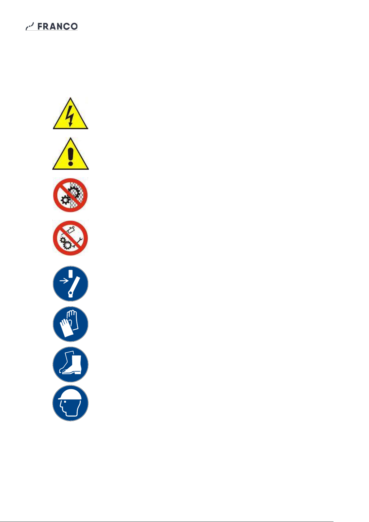
1.6 Pictograms .............................................................................................................................5
1.7 Applications............................................................................................................................7
1.8 Versions .................................................................................................................................7
1.9 Machine identification and nameplate data ............................................................................7
1.10 Description of the device......................................................................................................8
1.11 Transport and handling.........................................................................................................9
1.12 Warranty...............................................................................................................................9
1.13 Manufacturer's identification data.........................................................................................9
1.14 Declarations .........................................................................................................................9
1.15 EC Declaration of Conformity.............................................................................................10
2 - INSTALLATION ................................................................................................................11
2.1 Preliminary Operations.........................................................................................................11
2.2 Positioning............................................................................................................................11
2.3 Electrical Connections..........................................................................................................12
2.4 Water supply ........................................................................................................................12
3 - OPERATION .....................................................................................................................12
3.1 Preliminary Operations.........................................................................................................12
3.2 First Start-up.........................................................................................................................12
3.3 Start-up and Operation.........................................................................................................13
3.4 Adjusting the water flow rate ................................................................................................13
3.5 Stopping...............................................................................................................................13
4 - MAINTENANCE ................................................................................................................14
4.1 Disk Cleaning.......................................................................................................................14
4.2 Cleaning the Tank and Reservoir.........................................................................................14
4.3 Replacing and cleaning the pump ........................................................................................14
4.4 Replacing the rotating disc...................................................................................................15
4.6 Nozzle Replacement ............................................................................................................16
4.7 Accessories..........................................................................................................................16
5 - TECHNICAL CHARACTERISTICS...................................................................................17
5.1 Technical Data .....................................................................................................................17
5.2 Overall dimensions...............................................................................................................17
5.3 Circuit diagrams ...................................................................................................................18
6. SPARE PARTS LIST..........................................................................................................19
7. PROBLEM-SOLVING GUIDE ............................................................................................21

Operation and Maintenance Manual - UCP Fly Mobile
3
1 - INTRODUCTION
1.1 General Warnings Safety
This appliance must only be used for the function for which it was designed: 'Adiabatic humidifier/cooler'. Any
other use is to be considered improper and dangerous. Franco s. r. l. cannot be held responsible for any
damage resulting from improper, incorrect and unreasonable use or if the appliance is used in installations
which do not comply with current safety regulations.
- Check the integrity of the appliance when opening the packaging, paying particular attention to damage or
deformations of plastic parts that may lead to breakage and/or malfunction during use. In such cases, do not
connect the machine to the mains. Carry out a general inspection of the machine periodically.
- Before connecting the appliance, make sure that the rating plate data correspond to those of your electrical
distribution network. The data label (see par. 1.9) is located on the back of the appliance.
- Observe the safety regulations indicated for electrical equipment and in particular:
•Follow the installation instructions of the appliance.
•Do not place objects on the humidifier.
•Prevent children and/or incapacitated persons from using the device without proper supervision;
•Do not touch the humidifier during operation or while the disc is stopped;
•Never immerse the device in water or any other liquid.
•Do not put any objects inside the tank as the device could be irreparably damaged.
•Do not use accessories, spare parts or components not specified or supplied by the manufacturer.
•Avoid touching the device with wet or damp hands
•Do not pull the power cables or expose them to a risk of shearing.
•Do not leave the device exposed to the weather (rain, sun, etc.).
•In the event of a fault or malfunction of the device, switch it off immediately and disconnect the power
supply. Do not attempt to open or tamper with the appliance: contact a qualified technician.
•Do not attempt to fill or empty the tank when the appliance is in operation.
1.2 Guidelines for the proper disposal of the product
Pursuant to European Directive 2012/19/EU:
At the end of its useful life, the product must not be disposed of with urban waste.
It can be handed in at the special separate waste collection centres set up by
municipalities, or at retailers who provide this service. By disposing of the product
separately, you can avoid possible negative consequences for the environment and health
resulting from its improper disposal, and allows you to recover the materials of which it is
composed in order to achieve significant savings in energy and resources. To emphasise
the obligation to dispose of electrical and electronic equipment separately, the product is marked with a
crossed-out wheeled bin.
1.3 Conventions used in this manual
The manual is divided into chapters, within which the operators to whom the instructions are addressed are
specified, where necessary, in order to operate the machine safely.
The sequence of chapters responds to the temporal logic of the machine's life.
To facilitate immediate understanding of the text, terms, abbreviations and pictograms are used, the meaning
of which is indicated below.

Operation and Maintenance Manual - UCP Fly Mobile
4
ABBREVIATIONS
Cap. = Chapter
Par. = Paragraph
Page = Page
Fig. = Figure
Tab. = Table
UNIT OF MEASUREMENT
The units of measurement used are those of the International System (SI).
1.4 Keeping and updating the instruction manual
The instruction manualmust be kept with care and must accompany the machine in all changes of ownership
that it may undergo during its life. Parts must not be removed, torn off or arbitrarily modified.
The manual should be stored in an environment protected from humidity and heat and in the immediate
vicinity of the machine to which it refers. At the request of the user, the manufacturer can provide additional
copies of the machine instruction manual.
You can make a request by writing to support@francosrl.com
The Manufacturer reserves the right to modify the design and make improvements to the machine without
notifying the Customer, and without updating the Manual already delivered to the user. However, in the event
of changes to the machine installed at the Customer's premises, agreed with the Manufacturer and entailing
the amendment of one or more chapters of the Instruction Manual, it will be the Manufacturer's responsibility
to send the users concerned the chapters affected by the change.
It is the responsibility of the user to replace the old chapters, homepage and table of contents with the new
ones in all copies owned.
The Manufacturer is responsible for the original Italian language version; in the event of any doubts
regarding the translated versions, please refer to the Italian language and contact the Manufacturer
(support@francosrl.com) for due verification.
1.5 Addressees
This manual is intended for the Installer, Operator and Qualified Personnel authorised to service the machine.
OPERATOR:means the person(s)in charge of installing, operating, adjusting, cleaning, repairing and moving
a machine and performing the simplest maintenance operations;
QUALIFIED PERSONNEL/QUALIFIED WORKMAN: this refers to those persons who have attended
specialisation courses, training, etc. and have experience in the installation, commissioning and
maintenance, repair, transport of the machine.
The machine is intended for industrial use, and therefore professional and not general use, so its use must
be entrusted to qualified persons, in particular who
•have reached the age of majority;
•They are physically and mentally fit to perform work of particular technical difficulty;
•Have been properly instructed in the use and maintenance of the machine;
•They were judged by their employer to be fit to perform the task entrusted to them;
•Be able to understand and interpret the operator's manual and safety instructions;
•They are familiar with emergency procedures and their implementation;
•Possess the ability to operate the specific type of equipment;
•Be familiar with the specific rules of the case;
•Have understood the operating procedures defined by the machine manufacturer.

Operation and Maintenance Manual - UCP Fly Mobile
5
The appliance may be used by persons with reduced physical, sensory or mental capabilities, or lack of
experience or the necessary knowledge, provided that they are supervised or have received instructions
concerning the safe use of the appliance and understanding of the dangers involved.
1.6 Pictograms
This section explains the meaning of the pictograms indicating the operator's qualification, the state of the
machine, the hazards and the obligations/prohibitions to be observed. Their use makes it possible to quickly
and unambiguously provide the information required for the correct use of the machine in safe conditions.
PICTOGRAMS RELATING TO OPERATOR QUALIFICATION
Symbol
Description
General labourer: an operator without specific skills, capable of carrying out only simple
tasks on the instructions of qualified technicians.
Driver of lifting and handling equipment: an operator qualified to use lifting and handling
equipment and machines (strictly in accordance with the manufacturer's instructions), in
accordance with the laws in force in the country of the machine user.
Mechanical maintenance technician: qualified technician, capable of operating the
machine under normal conditions, operating it with jogging inching operation (JOG) with
protections deactivated, working on mechanical parts to carry out the necessary
adjustments, maintenance and repairs. Typically, he is not qualified to work on electrical
systems where voltage is present.
Electrical maintenance technician: A qualified technician, capable of operating the
machine under normal conditions, operating it with jogging inching operation (JOG) with
protections deactivated, is proposed for all work of an electrical nature for adjustment,
maintenance and repairs. He is able to work in the presence of voltage inside cabinets and
junction boxes.
Manufacturer's technician: qualified technician made available by the manufacturerto carry
out operations of a complex nature in particular situations or, in any case, as agreed with
the user. The skills are, depending on the case, mechanical and/or electrical and/or
electronic and/or software.

Operation and Maintenance Manual - UCP Fly Mobile
6
SAFETY PICTOGRAMS (ISO 7010)
The pictograms contained in a triangle indicate DANGER.
The pictograms contained in a circle impose a PROHIBITION/OBLIGATION.
Pictogram
Description
Dangerous electrical voltage.
Generic danger.
Do not remove safety devices.
Prohibition of cleaning, oiling, greasing, repairing or
adjusting moving parts by hand.
Obligation to cut power before starting work or
repairs.
Protective gloves compulsory.
Compulsory safety footwear.
Mandatory protective helmet.

Operation and Maintenance Manual - UCP Fly Mobile
7
1.7 Applications
The UCP Fly Mobile can be used for humidification, dust suppression or delivery of atomised sanitizing
products in small to medium-sized residential, commercial, agricultural or industrial environments.
The device can also be used as an adiabatic cooler. This is possible because atomised water in contact
with ambient air tends to evaporate, absorbing heat and lowering the temperature. The cooling capacity
depends on many variables, such as temperature, room humidity and air distribution.
The UCP Fly Mobile is mounted on a trolley with integrated water tank, which allows the machine to be easily
moved within the room to be humidified or cooled according to the customer's needs, ensuring maximum
versatility of use.
This machine must only be used for the purpose
for which it was designed:
HUMIDIFICATION / ADIABATIC COOLING
All other uses are to be considered improper and potentially dangerous.
1.8 Versions
The UCP Fly Mobile centrifugal humidifier is available in the following version:
3109000 UCP Fly Mobile H25 version with an air flow of 1800 m³/h 230V ~ 50Hz
1.9 Machine identification and nameplate data
Each machine is identified by an EC nameplate on which the article code, serial number and technical data
of the machine are indelibly marked (Fig. 1.9.1).
Always quote these references for any communication with the manufacturer or service centres.
Fig.1.9.1 CE Data plate

Operation and Maintenance Manual - UCP Fly Mobile
8
1.10 Description of the appliance
Main parts of the unit (Fig. 1.10.1)
Rotary disc
Disc cap
Tub lid
Rear cover
Pump
Nozzle
Regulating
valve
Fixed disk
Protection grid
Water collection tank
Electric box
Protection grid
Fan
Electric motor
Return pipe
Delivery pipe
Pump cable
connector
On/Off switch
Tank
60 L
Braked
wheels
Trolley

Operation and Maintenance Manual - UCP Fly Mobile
9
1.11 Transport and handling
The machine is shipped in robust packaging.
Take care when opening the packaging to avoid damaging components. Check the integrity
of the machine by checking that there are no visibly damaged parts. Do not dispose of
packaging elements in the environment: they must be placed in suitable collection areas.
The UCP Fly Mobile is a wheeled unit that can be moved on flat surfaces without the aid of
lifting and transport equipment.
WARNING! Before making any moves:
a. stop the machine;
b. Disconnect the machine from the mains;
If it is necessary to lift the machine, use a suitable lifting device (pallet truck, forklift truck, etc.). The weight is
indicated on the nameplate and in the technical data table (see Section 5.1).
1.12 Warranty
This appliance is guaranteed for 12 months from the date of manufacture for all faults attributable to a proven
manufacturing or material defect. The warranty does not cover all parts damaged by transport, bad or
incorrect maintenance, neglect, incapacity for use, improper use, tampering by unauthorised personnel, and
in any case causes beyond the control of Franco s.r.l. of Cervasca (CN). During the warranty period, Franco
s.r.l. undertakes to supply, free of charge, those parts that are found to be defective at source.
The intervention must be carried out by an authorised and qualified technician.
1.13 Manufacturer's identification data
Manufacturer
FRANCO s.r.l.
Legal - administrative headquarters
VIA NAZIONALE, 80 - 12010 CERVASCA (CN) - ITALY
Contact
Tel.: (0039) 0171 - 61.16.63
Email: support@francosrl.com
Web: francosrl.com
1.14 Declarations
The machine to which this manual refers is manufactured in accordance with the relevant European
Community legislation applicable at the time of its placing on the market.
The machine is not among those mentioned in Annex IV of Directive 2006/42/EC.

Operation and Maintenance Manual - UCP Fly Mobile
10
1.15 EC Declaration of Conformity
THE MANUFACTURER
FRANCO s.r.l.
Company
Via Nazionale, 80 12010 CN
Address Postcode Province
Cervasca Italy
City State
DECLARE under their own responsibility that the machine
Humidifier / Cooler UCP Fly Mobile H25
Description Model
3109000
Article code
UCP Fly Mobile Humidifier/Cooler
Trade name
Room humidification/cooling
Intended use complies with the following European Directives:
2006/42/EC Machinery Directive
(2014/35/EU) (Low Voltage Directive)
2014/30/EU Electromagnetic Compatibility Directive
Harmonised standards and reference specifications used:
EN 12100:2010
EN 60335-1:2012 + A11 +A13 +A1 + A14 + A2 +A15:2021
EN 60335-2-98:2003/A11:2019
EN 60335-2-41:2003/A2:2010
EN 60034-1:2010
EN 55014-1:2017, EN 55014-2:2015, EN 61000-6-1:2016, EN 61000-6-3:2010
Legal person authorised to set up the Technical File:
FRANCO s.r.l.
Name
Via Nazionale, 80 12010 CN
Address Postcode Province
Cervasca Italy
City State
Place and date of document
The manufacturer
Cervasca, 04/02/2022
Signature
Rev. 00/2022
Marco Fantino
Administrator

Operation and Maintenance Manual - UCP Fly Mobile
11
2 - INSTALLATION
2.1 Preliminary Operations
In order to make the UCP Fly Mobile humidifier operational, it is necessary to have:
•Electrical network with voltage and frequency characteristics suitable for the machine, with earthing and
protective devices;
•Ambient temperature during operation: must be between 1°C and 40°C
•Temperature of the water and liquids used: must not exceed 35°C.
•Drinking water with low fixed residue or treated water. The quality of the water affects the frequency of
maintenance and the proper functioning of the humidifier.
In particular, follow the prescriptions of standard UNI 8884 "Characteristics and
treatment of water in cooling and humidification circuits", which requires a conductivity
of less than 100 μS/cm and a total hardness of less than 5°fH (50 ppm of CaCO3), or
another equivalent national standard, to avoid the accumulation of limescale deposits
or incrustations that could compromise the proper functioning of the appliance.
2.2 Positioning
The UCP Fly Mobile humidifier must be placed on a flat, level surface in a horizontal position. When the
machine is in the desired position, lock the two rear wheels using the brakes before starting it.
Observe the recommended minimum distances for proper machine operation.
To avoid the formation of condensation, maintain a distance of at least 1m between the humidifier and
surrounding walls. The distance to the wall in front of the machine should be assessed according to the size
of the room and the humidification or cooling requirements.
The unit is supplied as standard with a front and rear grille to protect the rotating parts (centrifuge disc, fan).
Do not remove protective devices. Observe the safety distances from moving
parts prescribed by standard UNI EN ISO 13857:2008. Any maintenance or repair
operations requiring the removal of protections must only be carried out by
qualified personnel, after having stopped the machine and de-energised it.

Operation and Maintenance Manual - UCP Fly Mobile
12
2.3 Electrical Connections
•Ensure that the electrical installation to which the appliance is connected complies with
the electrical safety regulations in force in the country of destination.
•Ensure that the supply voltage characteristics comply with what is stated on the
nameplate of the device.
•Earthing is mandatory.
The unit is supplied as standard with a power cable with Schuko plug to be connected to a 230V 50Hz single-
phase socket with earth. An ON/OFF switch is provided on the unit for manual start and stop.
2.4 Water supply
Manually fill the tank built into the machine (60 litre capacity) with clean water. For the characteristics of the
water to be used, see Section 2.1. During operation, regularly check the water level in the tank on the scale
and top up when necessary.
3 - OPERATION
3.1 Preliminary Operations
Before starting up the humidifier, check that
•The unit is placed in a stable, flat and level position with the rear wheels braked;
•The power cable is correctly connected to a grounded socket;
•The power cable is correctly positioned and not pinched or overstretched;
•The humidifier is free and clean;
•The water tank is full;
•The water supply and return pipes are connected.
3.2 First Start-up
•Set the switch to I (ON) (Fig. 3.2.1)
•Check the correct airflow direction and direction of rotation of the disc (Fig. 3.2.2);
•Open the water control valve and check that there are no leaks along the circuit.
Fig. 3.2.1 Fig. 3.2.2
The pump must never run dry. Add water to the tank regularly during operation to avoid
damaging the pump.
The temperature of the liquids used must not exceed 35°C
Fluu
Flow

Operation and Maintenance Manual - UCP Fly Mobile
13
3.3 Start-up and operation
As soon as the machine is powered up, the fan and pump start up. The pump, located at the bottom of the
tank, circulates the water to the rotating disc, which nebulises it, and the fan generates a flow of air that
distributes the mist produced in the environment. The unmisted water collects in the tank and is returned to
the tank through the return pipe.
During operation:
•Regularly check the water level in the tank on the scale and top up according to the water
consumption of the humidifier.
•Do not move the appliance while it is in operation. Switch off and unplug it before making any
movements.
•Do not disconnect the power cord of the pump. The pump should only be disconnected when
the machine is switched off and not energized for cleaning and maintenance.
•In case of stoppages or other faults, please refer to Chapter 7 'Troubleshooting'.
3.4 Setting the water flowrate
Adjust the water flowrate by acting on the regulating valve on the delivery
pipe until fine atomisation is achieved without entrainment of droplets from
the rotating disc. Centrifugal humidifiers produce droplets of varying sizes, on
average between 10 and 30 mm. The size of the droplets produced depends
on the flow rate setting and various environmental factors.
The UCP Fly Mobile is capable of atomising up to a maximum of 25 l/h of
water. An excessive water flow rate could cause an increase in droplet size and adversely affect the mist
quality.
3.5 Stopping
After each use:
•Switch the machine off by turning the switch to the '0' (OFF) position;
•Pull the plug;
•Empty the tank completely by removing the drain plug at the bottom of the front, after positioning the unit
above a suitable drainage point.
WARNING!
Stagnant water can cause the proliferation of bacteria and microorganisms that are
harmful to health. It is therefore mandatory to prevent stagnation.
Drain the water from the tank regularly after use. Never leave stagnant water inside the
tank when the machine is not in use. (see also chapter 4.2. "Cleaning the tank and reservoir").
In addition to safety reasons, regular water renewal is also necessary to keep the appliance clean
and free of lime scale, mould, etc.
OPEN
CLOSED

Operation and Maintenance Manual - UCP Fly Mobile
14
4 - MAINTENANCE
The operations described in this chapter must only be carried out by authorised and qualified
personnel, using suitable personal protective equipment. Before carrying out any work, disconnect
the appliance from the mains and water supply.
Check periodically that the water flow to the centrifugal disc is correct. Adjust the flow regulator if necessary.
Keep discs, tank and internal components clean to prevent dirt accumulation.
4.1 Disk Cleaning
•Keep the discclean to prevent limescale build-upor dirt accumulation thatcould cause increasedvibration
or coarse spraying.
•To clean the rotating disc, use a soft, damp cloth and a non-toxic, solvent-free cleaning agent, wiping
without pressing too hard.
•Do not use solvents.
•The hard disk must be cleaned with a brush with stiff bristles, rubbingthe teeth being careful not to damage
them. Any lime deposits can be removed with vinegar, lemon or another specific, non-toxic and solvent-
free product.
4.2 Cleaning of the tank and reservoir
Emptying the tank and renewing the water (after each use)
•Place the appliance over a suitable drainage point and unscrew the front drain plug of the tank to
completely remove the contained water.
•When the operation is complete, be sure to reinsert and tighten the drain plug.
•Before using the machine again, fill the tank with clean running water.
Complete tank cleaning
If more thorough cleaning of the tank is required, disconnect the pump power cable, disconnect the delivery
hose from the pump, pull out the delivery and return hoses and remove the tank from the trolley to facilitate
cleaning.
•Clean the inside of the tank using a non-toxic, solvent-free cleaning agent, possibly with the aid of a
pressurised water jet to remove particularly difficult-to-remove dirt, encrustations, etc.
•Rinse and replace the tank on the trolley, making sure to reinsert the drain plug and reconnect the pump
power cable, and the delivery and return hoses.
Cleaning the water collection tank
•Inspect and clean the water collection tray periodically.
•To access the tank, unscrew the two screws securing the cover and remove it.
•Clean the inside of the tub with a cloth or sponge by gently rubbing the walls. Do not use solvents.
4.3 Replacing and cleaning the pump
To replace the pump, proceed as follows:
•Disconnect the pump power cable;
•Remove the tank cover;
•Disconnect the pump from the bottom of the tank and pull it out through the filling hole;
•Disconnect the delivery hose from the pump to be replaced and connect it to the new pump;
•Insert the pump into the tank by securing it at the bottom using the suction cups;
•Reconnect the power cable and start the machine to check operation.

Operation and Maintenance Manual - UCP Fly Mobile
15
The pump does not require any special maintenance. However, it is advisable to clean the internal rotating
parts periodically, depending on the quality of the water used. For this purpose:
•Disconnect and remove the pump from the tank as described above;
•Remove the delivery nozzle with the help of a screwdriver if necessary;
•Remove and check the rotor and impeller and clean them with lukewarm water and a brush. Any lime
deposits can be removed with vinegar, lemon or special products. Do not use solvents;
•Refit the nozzle, reposition the pump inside the tank and reconnect the connector on the power cable.
4.4 Replacing the rotating disc
•Remove the front protection grille by unscrewing the 3 fixing screws.
•Remove the central cap of the rotating disc by prying into the recess with a small slotted screwdriver (Fig.
4.4.1)
•Using a screwdriver (hexagonal 7), unscrew the rotating disc's M4x16 fastening screw to the motor shaft
and its washer (Fig. 4.4.2).
Fig. 4.4.1 Fig. 4.4.2
•Insert the M8x40 screw supplied with the machine into the centre hole of the rotating disc (Fig.
4.4.3)
•Use a screwdriver spanner (hexagonal 13) to tighten the screw, which will push the disc out
effortlessly as it enters the hole. (Fig. 4.4.4)
Leverage in
the recess
Screw M4x16

Operation and Maintenance Manual - UCP Fly Mobile
16
Fig. 4.4.3 Fig. 4.4.4
•Once the disc is removed, remove the M8x40 screw by unscrewing it from the rotating disc.
•Apply a small amount of grease to the crankshaft and fit the new disc, checking the alignment
of the keys and applying pressure to the centre, without knocking or forcing too hard. Replace
the washer, M4 screw and plug. Check that the 4 mm thick spacer (see Section 5.3 "Spare
parts list" Item 5) is correctly positioned between the fixed disc and rotating disc.
4.6 Replacing the nozzle
•After removing the rotating disc (see Section 4.4), remove the nozzle by unscrewing the two fixing
screws.
•Push the grey ring on the elbow coupling (see Section 5.3 'Spare parts list' item 19) to the rear of the
disc and, while holding it down, pull the nozzle to be replaced.
•Position the new nozzle by repeating the sequence in reverse.
4.7 Accessories
A complete range of accessories that can be combined with your UCP Fly Mobile is available on request.
Ask your supplier for the accessories catalogue for more details.
Screw M8x40

Operation and Maintenance Manual - UCP Fly Mobile
17
5 - TECHNICAL CHARACTERISTICS
5.1 Technical data
Atomisation capacity
l/h
up to 25
Power supply
~ single-phase
IP rating
IP55
Weight
kg
27
Air flow rate
m³/h
1800
Fan/humidifier motor
Power
W
347
Voltage
V/Hz
230/50
Current
A
2,1
Pump motor
Power
W
33
Voltage
V
230/50
Current
A
0,1
5.2 Overall dimensions

Operation and Maintenance Manual - UCP Fly Mobile
18
5.3 Electric Diagram
Ensure that the electricalsupply voltage characteristics are in accordance with the specification
table.
Install a magnetothermal differential circuit breaker in the power supply circuit upstream of the
equipment.
Also ensure that:
- all electrical connections have been made according to the instructions in this manual;
- the earthing has been carried out correctly;
- all applicable safety regulations have been complied with;
If the power cable is damaged, it must be replaced by the manufacturer or its technical service
department or a similarly qualified person in order to prevent any risk.

Operation and Maintenance Manual - UCP Fly Mobile
19
6. SPARE PARTS LIST
Use only original spare parts.
When ordering spare parts, always
specify:
•Machine model
•Construction Year /Serial no.
•Spare part code
•Quantity
•Shipping address

Operation and Maintenance Manual - UCP Fly Mobile
20
Pos.
Code
Description
Qty
22
8202000
VALVE 3/8"
1
23
3102006
FULL TROLLEY
1
24
7303005
PASSAGE
1
25
8202008
STRAIGHT FITTING F 1/2"- 3/8"
1
26
3102005
3/8" SUPPLY/RETURN PIPE KIT
1
27
8202009
ELBOW COUPLING 3/8"
1
28
1800020
COMPLETE SHELTER
1
29
5001500
230V 50Hz MOTOR
1
30a
6003004
WASHER 5x15 DIN 125 - A 7,4
8
30b
6003004
WASHER 5x15 DIN 125 - A 7,4
8
31a
6003051
GROWER WASHER D.5 DIN 128 - A5
4
31b
6003051
GROWER WASHER D.5 DIN 128 - A5
4
32a
6002501
NUT M5 DIN 934
4
32b
6002501
NUT M5 DIN 934
4
33
6001006
T.E. SCREW M5x25 DIN 933
4
34
6001007
SCREW M5x20 DIN 933
4
35
3101010
MOTOR MOUNT
1
36
3101011
UCP-FLY SUPPORT
2
37
3101001
UCP-FLY BODY
1
38
6003005
WASHER M4x12 DIN 125
2
39
3105500
COMPLETE ELECTRICAL BOX
1
40
3105010
FAN UCP-FLY H15
1
3105003
UCP-FLY H20 FAN
3105004
FAN UCP-FLY H25
41a
6003007
DIN 125 WASHER - A 4.3
1
41b
6003007
DIN 125 WASHER - A 4.3
4
42
3101020
SAFETY NET
1
43
7004000
POWER CABLE+PLUG
1
Pos.
Code
Description
Qty
1
6002004
SCREW 4.2x9.5 DIN 7981
3
2
1801030
PROTECTION NET (10mm pitch)
1
1801031
PROTECTION NET (30mm pitch)
3
1800003
ROTATING DISC CAP
1
4a
6001001
SCREW M4x16 DIN 933
1
4b
6001001
SCREW M4x16 DIN 933
2
4c
6001001
SCREW M4x16 DIN 933
1
4d
6001001
SCREW M4x16 DIN 933
4
5
1801006
ROTATING DISC FIXING WASHER
1
6
1801002
ROTATING DISK
1
7
1801008
ROTATING DISK SPACER 4mm
1
8
6002000
SCREW 4.2x13 DIN 7982
3
9
6001502
SCREW M6x20 DIN 7991
4
10
6001501
SCREW M4x16 DIN 7991
4
11a
6003000
WASHER 4.3x9 DIN 125
4
11b
6003000
WASHER 4.3x9 DIN 125
2
12a
6002500
NUT M4 DIN 934
4
12b
6002500
NUT M4 DIN 934
2
13
1800022
UGELLO
1
14
6002003
SCREW 2.9x9.5 DIN 7981
2
15
1801012
FIXED DISC
1
16
6002002
SCREW 2.9x19 DIN 7982
2
17
1800017
TUB COVER (GREEN)
1
18
3107051
WATER TANK 60L
1
19
7308018
230V 50Hz PUMP
1
20
1806005
BATHTUB (GREEN)
1
21
7307008
CONNECTOR+CABLE KIT
1
Table of contents
Other FRANCO Accessories manuals