FRANCO 2903000 Instruction manual

INSTRUCTION MANUAL FOR
USE AND MAINTENANCE
ROOF COOLER
EVAPORATIVE COOLER
T R A N S L AT I O N O F O R I G I N A L I N S T R U C T I O N S
ENG L I SH
C O U N T R Y O F D E S T I N AT I O N : GB
Read this manual carefully
before installing and using the machine
Rev. 00/2022 Franco s. r. l. - Via Nazionale, 80 12010 Cervasca (CN)

FRANCO s.r.l. User and maintenance manual ROOF COOLER
2
INDEX
INDEX ......................................................................................................................................2
1 - INTRODUCTION.................................................................................................................3
1.1 General safety instructions .............................................................................................3
1.2 Warnings for the correct disposal of the product (EU) ....................................................3
1.3 Conventions used in this manual....................................................................................4
1.4 Keeping and updating the instruction manual................................................................. 4
1.5 Target audience..............................................................................................................4
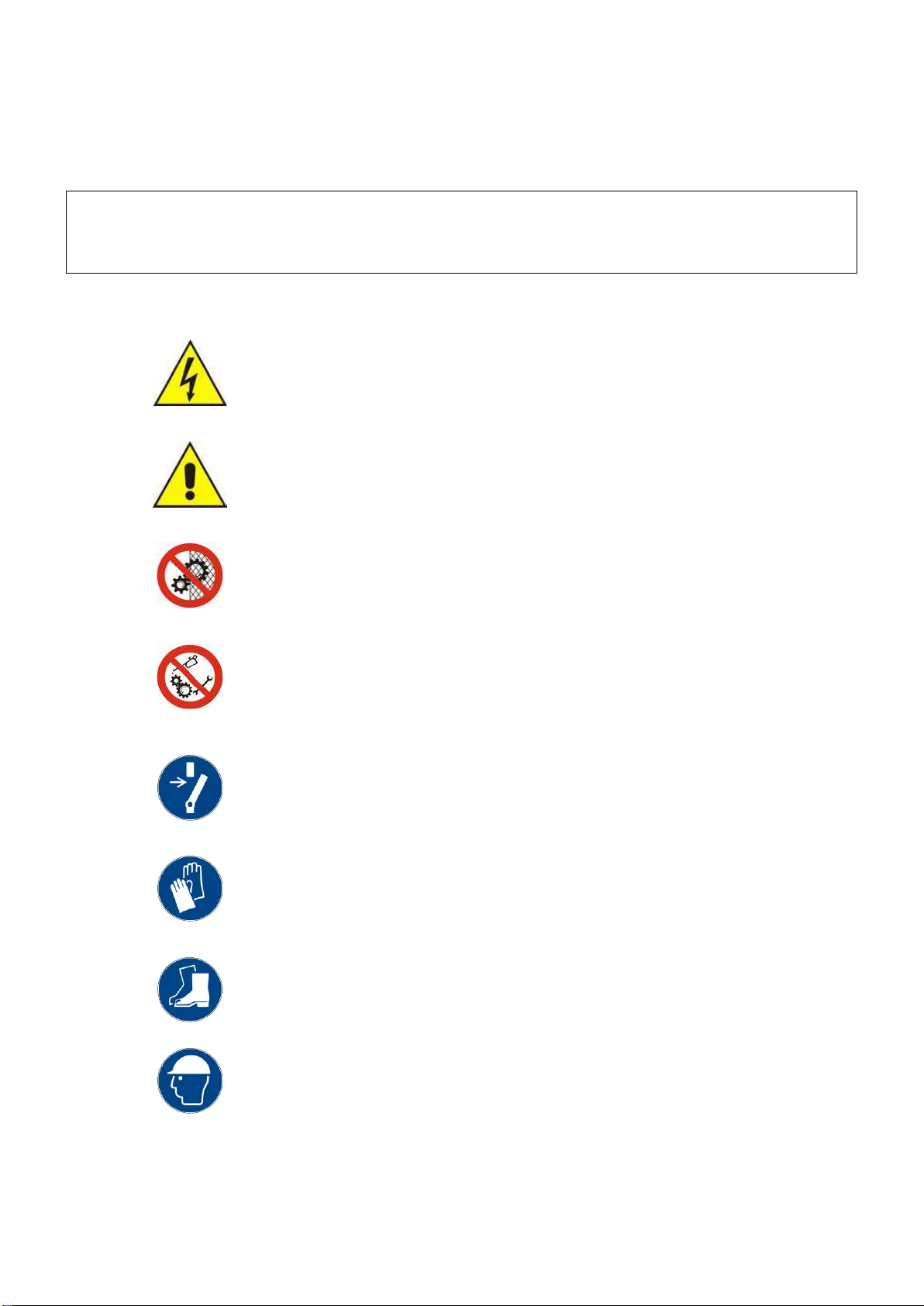
1.6 Pictograms...................................................................................................................... 5
1.7 Applications ....................................................................................................................7
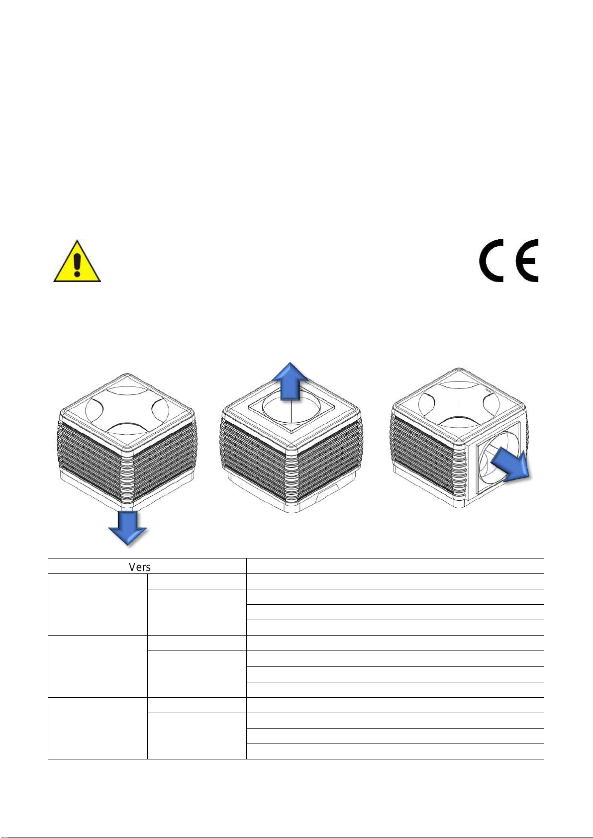
1.8 Versions..........................................................................................................................7
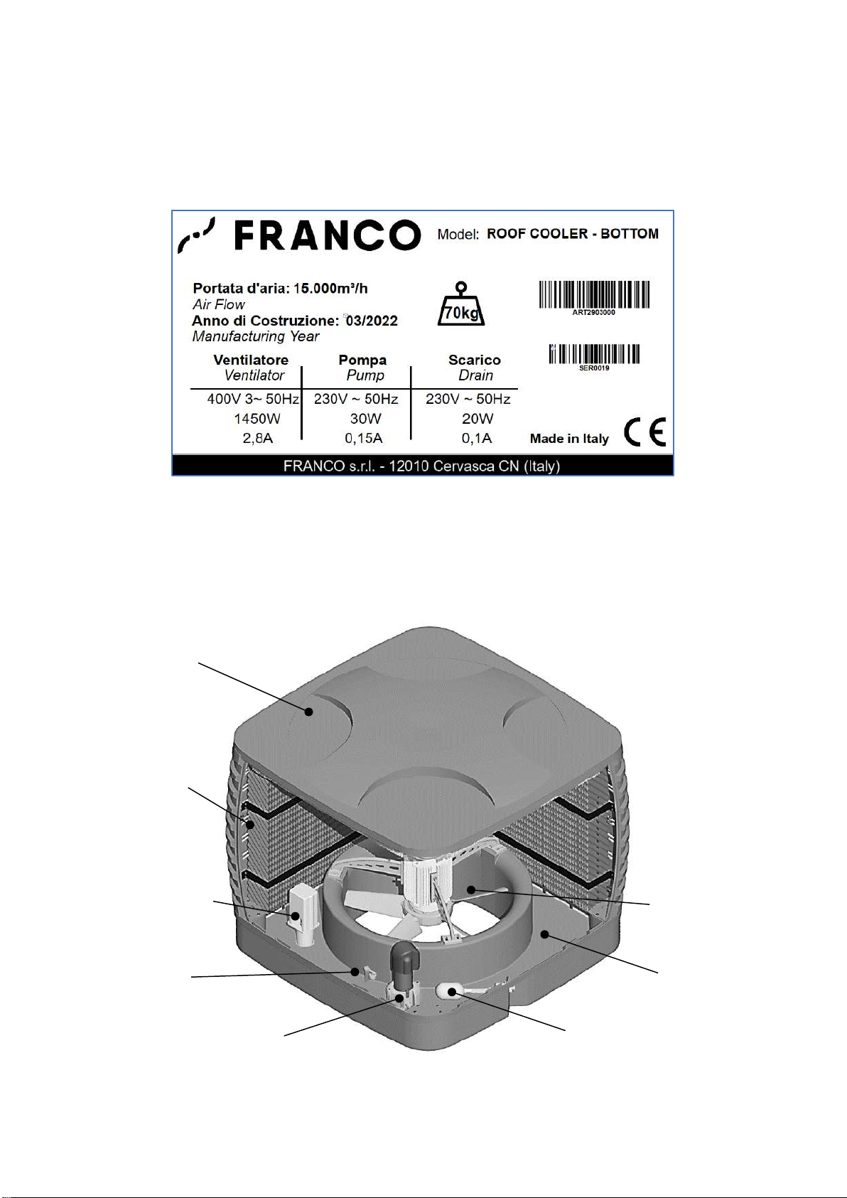
1.9 Machine identification data and plates............................................................................8
1.10 Description of equipment..............................................................................................8
1.11 Transport and handling.................................................................................................9
1.12 Warranty.......................................................................................................................9
1.13 Manufacturer's identification data .................................................................................9
1.14 Declarations..................................................................................................................9
1.15 Declaration of conformity............................................................................................10
1.16 Declaration of incorporation........................................................................................ 11
2 - INSTALLATION................................................................................................................ 12
2.1 Getting started..............................................................................................................12
2.2 Positioning....................................................................................................................12
2.3 Electrical connections...................................................................................................14
2.4 Hydraulic connections...................................................................................................14
3 - OPERATION..................................................................................................................... 15
3.1 Preliminary operations..................................................................................................15
3.2 First start-up.................................................................................................................. 15
3.3 Starting up ....................................................................................................................16
3.4 Optimum conditions of use ...........................................................................................16
3.5 Water discharge (bleed-off) ..........................................................................................16
4 - CLEANING AND MAINTENANCE ................................................................................... 17
4.1 Cleaning and maintenance programme........................................................................17
4.2 Cleaning and maintenance operations .........................................................................17
5 - TECHNICAL CHARACTERISTICS .................................................................................. 20
5.1 Overall dimensions ....................................................................................................... 20
5.2 Technical data ..............................................................................................................20
5.3 Electrical connections...................................................................................................21
5.4 Spare parts list.............................................................................................................. 23
6 - PROBLEM-SOLVING GUIDE........................................................................................... 26

FRANCO s.r.l. User and maintenance manual ROOF COOLER
3
1 - INTRODUCTION
1.1 General safety instructions
This appliance must only be used for the function for which it was designed "Adiabatic cooler /
humidifier". Any other use is to be considered improper and dangerous. Franco s. r. l. cannot be held
responsible for any damage resulting from improper, incorrect and unreasonable use, such as, for
example:
- installation errors
- incorrect power or water supply
- unauthorised mechanical or electrical modifications
- removal of guards or safety devices
- lack of maintenance
- use of non-original spare parts
- non-compliance with the operating and maintenance instructions
- When opening the packaging, check that the appliance is intact and does not show any damage or
deformation of the plastic parts. If this is the case, do not install the appliance and contact the service
department.
- Before connecting the appliance, make sure that the data on the rating plate (voltage, frequency, etc.)
correspond to those on the mains. The technical data label is located on the bottom side of the appliance
(see par. 1.9).
- Comply with the safety rules indicated for electrical equipment, and in particular:
•Follow the operating and maintenance instructions for the appliance.
•Do not place objects on the cooler.
•Prevent children and/or physically or mentally unfit persons from using the device without proper
supervision;
•Do not touch the cooler during operation.
•Never immerse the appliance in water or any other liquid, or hit it with pressurised water.
•Do not place any objects inside the appliance.
•Do not use accessories, spare parts and components not intended for or supplied by the
manufacturer.
•Avoid touching the device with wet or damp hands.
•Do not pull power cables or expose them to risk of shearing.
•In the event of a fault or malfunction, switch off the appliance immediately and disconnect the
power supply. Do not attempt to open or tamper with the appliance: contact the technical service.
•Do not attempt to fill or empty the drip tank manually when the appliance is in operation.
•Do not remove the guards during use.
•Do not install the device in explosion hazard areas.
1.2 Warnings for the correct disposal of the product (EU)
Pursuant to European Directive 2012/19/EU:
At the end of its useful life, the appliance must be delivered to the appropriate separate
waste collection points set up by the local authorities, or to retailers who provide this
service. Disposing of the product separately avoids possible negative consequences for
the environment and health, and allows the materials from which it is made to be
recovered, thus saving energy and resources. To emphasise the obligation to dispose of
electrical and electronic equipment separately, the product is marked with a crossed-out
wheeled bin.
Fig. 1.2.1

FRANCO s.r.l. User and maintenance manual ROOF COOLER
4
1.3 Conventions used in this manual
The manual is divided into chapters. Where necessary, pictograms are used to indicate the specific type
of operator for whom the chapter is intended (e.g. mechanical maintenance, service, etc.).
The sequence of chapters follows the phases of the machine's life.
To facilitate understanding of the text, terms, abbreviations and pictograms are used, the meaning of
which is indicated below.
ABBREVIATIONS
Cap. = Chapter
Par. = Paragraph
Page = Page
Fig. = Figure
Tab. = Table
UNITS OF MEASUREMENT
The units of measurement used are those of the International System (SI).
1.4 Keeping and updating the instruction manual
The manual is an integral part of the machine: it must therefore be stored with care and must accompany
the machine in all changes of ownership. Handle the manual with care, with clean hands and do not
place it on dirty surfaces. Do not remove, tear or arbitrarily modify any part. Keep the manual away from
moisture and heat and in the vicinity of the machine to which it refers.
Further copies of the instruction manual can be obtained from support@francosrl.com.
The manual contains the instructions for the machine model and version to which it is attached. In the
case of authorised modifications to installed machines, which involve the modification of parts of the
instruction manual, it is the manufacturer's responsibility to send the customer the parts affected by the
modification. The user must replace the old parts with the new parts in the manual he has.
The manufacturer is responsible for the original version in Italian; in case of doubts about the
translations, please refer to the Italian language and contact the manufacturer (support@francosrl.com)
for the necessary checks.
1.5 Target readers
OPERATOR: means the person or persons responsible for installing, operating, adjusting, cleaning,
repairing and moving a machine and for carrying out the simplest maintenance operations;
QUALIFIED PERSONNEL/QUALIFIED WORKERS: these are people who have attended specialised
courses, training, etc. and have experience in the installation, commissioning and maintenance, repair,
transport of the machine.
The machine is intended for industrial use, and therefore professional and not general use, so its use
must be entrusted to qualified personnel, in particular who:
•have reached the age of majority;
•are physically and mentally fit to carry out work of particular technical difficulty;
•have been properly instructed in the use and maintenance of the machine;
•have been judged by the employer to be suitable to carry out the task entrusted to them;
•are able to understand and interpret the operator's manual and safety instructions;
•know the emergency procedures and their implementation;
•are able to operate the specific type of equipment safely;
•are familiar with the applicable specific rules;
•have understood the operating procedures defined by the manufacturer of the machine.

FRANCO s.r.l. User and maintenance manual ROOF COOLER
5
The appliance may be used by persons with reduced physical, sensory or mental capabilities, or lack of
experience or knowledge, provided that they are supervised or have received instructions concerning
the safe use of the appliance and an understanding of the hazards involved.
1.6 Pictograms
This section explains the meaning of the pictograms indicating the operator's qualification, the state of
the machine, the hazards and the obligations/prohibitions to be respected. They provide rapid and
unambiguous information necessary for the correct and safe use of the machine.
PICTOGRAMS RELATING TO OPERATOR QUALIFICATION
Symbol
Description
General labourer: an operator with no specific skills, capable of carrying out only simple
tasks at the instruction of qualified technicians.
Driver of lifting and handling equipment: an operator qualified to use lifting and handling
equipment and machines (strictly following the manufacturer's instructions), in accordance
with the laws in force in the country of the machine user.
Mechanical maintenance technician: qualified technician, able to operate the machine
under normal conditions, to make it work with protections disabled, to intervene on the
mechanical parts to carry out the necessary adjustments, maintenance and repairs.
Typically, he is not qualified to work on live electrical installations.
Electrical maintenance technician: qualified technician, able to operate the machine under
normal conditions, to make it work with protections deactivated, is proposed to all
interventions of an electrical nature of regulation, maintenance and repairs. He is able to
work in the presence of voltage inside electrical cabinets and panels.
Manufacturer's technician: a qualified technicianprovided by the manufacturerto carry out
maintenance, troubleshooting, repair, etc. of a particularly complex nature. Skills may be
mechanical/electrical/electronic/software depending on the case.

FRANCO s.r.l. User and maintenance manual ROOF COOLER
6
SAFETY PICTOGRAMS (ISO 7010)
Pictograms contained within a triangle indicate a DANGER.
The pictograms contained in a circle impose a PROHIBITION (red) or an OBLIGATION (blue).
Failure to follow one or more of the instructions marked with these symbols may result in
personal injury or property damage for which the manufacturer cannot be held responsible.
All technical, legislative and accident prevention regulations in force in the country of
destination must also be observed.
Pictogram
Description
Dangerous electrical voltage.
General hazard.
Do not remove safety guards.
It is forbidden to clean, oil, grease, repair or
adjust moving parts by hand.
Obligation to switch off power before starting
work or repairs.
Protective gloves are mandatory.
Mandatory safety footwear.
Helmet mandatory.

FRANCO s.r.l. User and maintenance manual ROOF COOLER
7
1.7 Applications
The ROOF COOLER is an evaporative cooler for large rooms, such as workshops, industrial
departments, commercial and civil buildings, agricultural and livestock premises, etc., which works
based on the principle of adiabatic cooling. Warm air is drawn in from outside, flows across the high-
efficiency evaporative panels and comes into contact with the water flowing through the panels from top
to bottom. The evaporation removes heat from the air and naturally lowers its temperature. The fresh
air is then conveyed and distributed to the space to be cooled through a duct. The cooling capacity
depends on the temperature, room humidity and air distribution.
As well as a cooler, the unit can also be used as a humidifier for large room volumes, in industrial, civil,
agricultural and livestock applications, or as a simple ventilator, when cooling or humidification is not
necessary.
The materials used guarantee reliability and durability, even in the most critical environments.
This machine must only be used for the purpose
for which it was designed: "Adiabatic cooling/humidification". All
other uses are considered improper and therefore potentially
dangerous.
1.8 Versions
The ROOF COOLER evaporative cooler is available in the following versions:
BOTTOM
TOP
SIDE
Version
Article number
Power supply
Motor
Bottom
(air exit
from below)
without fan*
2903100
230V 50Hz
-
with fan
2903000
400V 3N~ 50Hz
fixed speed
2903001
400V 3N~ 50Hz
variable speed
2903005
230V 50Hz
variable speed
Top
(air exit from
above)
without fan*
2903011
230V 50Hz
-
with fan
2903010
400V 3N~ 50Hz
fixed speed
2903013
400V 3N~ 50Hz
variable speed
2903012
230V 50Hz
variable speed
Side
(air exit on
one side)
without fan*
2903021
230V 50Hz
-
with fan
2903020
400V 3N~ 50Hz
fixed speed
2903022
400V 3N~ 50Hz
variable speed
2903024
230V 50Hz
variable speed
*Versions without fan must be integrated in a dynamic ventilation system with a maximum air flow of
15000 m³/h.

FRANCO s.r.l. User and maintenance manual ROOF COOLER
8
1.9 Machine identification data and plates
Each machine is identified by a CE plate on which the technical reference data are indelibly marked.
Always quote these references in any communication with the manufacturer or service centres (Fig.
1.9.1).
Fig.1.9.1
1.10 Description of equipment
Main components of the evaporative cooler
Fig.1.10.1
Machine
body
Water
pump
Evaporative
panel
Drain valve
Filling valve ½"
Ventilator
Level
sensor
Water collection
tank

FRANCO s.r.l. User and maintenance manual ROOF COOLER
9
1.11 Transport and handling
The unit is packed on pallets, with protective film and fixing straps.
Care must be taken during transport, unloading, handling and unpacking to avoid damaging the
machine.
Check the integrity of the machine by checking that there are no visibly damaged parts. If there is any
damage due to transport, do not install the machine and contact the manufacturer.
Do not dispose of packaging elements in the environment, but place them in the appropriate collection
places.
ATTENTION!
Before moving the appliance:
a. stop the unit;
b. switch off the power supply;
c. cut off the water supply.
Transport, handling and lifting operations must be carried out by qualified personnel, using suitable
means, personal protective equipment and procedures according to the weight and size of the
equipment, in compliance with the occupational safety regulations in force in the country of destination.
For lifting, use ropes or straps with suitable characteristics, positioned so as not to damage the
packaging and the appliance (see weight on the nameplate). Do not stand under suspended loads
and/or in the working area of lifting equipment.
1.12 Warranty
This appliance is guaranteed for 12 months from the date of manufacture for all faults attributable to a
proven manufacturing or material defect. The warranty does not cover all parts damaged by transport,
bad or incorrect maintenance, neglect, inability to use, improper use, tampering by unauthorised
personnel and in any case by causes beyond the control of Franco s.r.l.. During the warranty period,
Franco s.r.l. undertakes to replace or repair free of charge those parts which prove to be defective at
the origin.
Any repair shall be carried out by a qualified and authorized technician.
1.13 Manufacturer's identification data
Manufacturer: FRANCO S.r.l.
Legal and administrative address: VIA NAZIONALE 80 - 12010 CERVASCA CN - ITALY
Tel. : (0039) 0171 - 61.16.63
E-mail: support@francosrl.com
www.francosrl.com
1.14 Declarations
The machine is manufactured in accordance with the relevant Community Directives applicable at the
time of placing on the market.
The machine is not included among those mentioned in All. IV of Directive 2006/42/EC.
The version code 2903100 is marketed as a partly completed machine, as it needs to be equipped with
a fan or integrated into ventilation systems with a maximum air flow of 15000 m³/h for operation.
The partly completed machinery is manufactured in accordance with the applicable requirements of the
European Directives in force at the time of placing on the market.
The partly completed machinery is not included among those mentioned in All. IV of Directive
2006/42/EC.

FRANCO s.r.l. User and maintenance manual ROOF COOLER
10
1.15 Declaration of conformity
(Annex IIa Dir. 2006/42/EC)
THE MANUFACTURER
FRANCO s.r.l.
Company
Via Nazionale, 80 12010 CN
Address Postcode Province
Cervasca Italy
City Country
DECLARES under its own responsibility that the machine
Cooler / Humidifier ROOF COOLER
Description Model
2903000; 2903001; 2903005; 2903010; 2903013; 20903012; 2903020; 2903022; 2903024
Art. No.
ROOF COOLER Evaporative cooler
Trade name
Room cooling / Humidification
Intended use
complies with the following European Directives:
2006/42/EC Machinery Directive
(2014/35/EU) (Low Voltage Directive)
2014/30/EU Electromagnetic Compatibility Directive
Harmonised standards and reference specifications used:
EN 12100:2010
EN 60335-1:2012 + A11 +A13 +A1 + A14 + A2 +A15:2021
EN 60335-2-80:2003 +A2:2009
EN 55014-1 :2017, EN 55014-2:2015, EN 61000-6-1:2016, EN 61000-6-3:2010
Legal entity authorised to establish the Technical File:
FRANCO s.r.l.
Name
Via Nazionale, 80 12010 CN
Address POSTCODE Province
Cervasca Italy
City State
Place and date of document
The manufacturer
Cervasca, 02/03/2022
Signature
Rev. 00/2022
Marco Fantino
Administrator

FRANCO s.r.l. User and maintenance manual ROOF COOLER
11
1.16 Declaration of incorporation
(Annex IIb Dir. 2006/42/EC)
THE MANUFACTURER
FRANCO S.r.l.
Company
Via Nazionale, 80 12010 CN
Address Postcode Province
Cervasca Italy
City Country
DECLARES that the partly completed machine
Cooler / Humidifier ROOF COOLER
Description Model
2903100; 2903011; 2903021
Art. No.
ROOF COOLER Evaporative cooler
Trade name
Room cooling in combination with dynamic ventilation systems with a maximum air flow of 15000 m³/h
Intended use
- meets the following applicable essential requirements:
RESS 1.1 to 1.7 of Directive 2006/42/C
- complies with the following EU directives:
Directive 2006/95/EC
Directive 2004/108/EC
The relevant technical documentation has been prepared in accordance with Annex VII B, Dir. 2006/42/EC.
The manufacturer, FRANCO s.r.l., undertakes to provide information relevant to the partly completed machinery
covered by this declaration, if requested, and prohibits its putting into service until the final machinery into which it
is to be incorporated has been declared in conformity with the provisions of Directive 2006/42/EC.
Legal entity authorised to establish the Technical Documentation:
FRANCO s.r.l.
Name
Via Nazionale, 80 12010 CN
Address Postcode Province
Cervasca Italy
City Country
Place and date of document
The manufacturer
Cervasca, 02/03/2022
Signature
Rev. 00/2022
Marco Fantino
Administrator

FRANCO s.r.l. User and maintenance manual ROOF COOLER
12
2 - INSTALLATION
2.1 Preliminary operations
To operate the ROOF COOLER, you need:
- Electrical network with voltage and frequency characteristics suitable for the machine, with earth
conductor and protection devices;
- Water supply connection. Required pressure: 2 to 4 bar
- Water drainage connection.
Connections to the electricity and water mains must be made by qualified personnel
in accordance with the safety regulations in force in the country of destination.
2.2 Positioning
The ROOF COOLER must be positioned respecting the minimum recommended distances that allow
the correct operation of the machine and maintenance.
For optimal operation, the ROOF COOLER should be installed outside the building, as required:
- on roof, flat or sloping, with bottom air outlet (Fig. 2.2.1)
- wall-mounted, with side, bottom or top air outlet (Fig. 2.2.2, 2.2.3, 2.2.4)
For an efficient cooling action and for the control of the room humidity, it is essential to ensure a
continuous renewal of the air in the room to be cooled, by means of ventilation openings of suitable
size, placed at the maximum possible distance from the cooler(s), which must be kept open during
operation. Instead of, or in addition to openings, some air extractors can be installed, so that the
extracted air flow rate is at least 80% of the air flow rate introduced into the room by the cooler(s).
The efficiency of the process, and therefore the room temperature drop, will be greater the higher the
temperature of the outside air and the lower its relative humidity.
ATTENTION!
•The installation must guarantee compliance with the requirements of standard UNI
EN ISO 13857:2008, with regard to protection against accidental contact by operators
with moving parts of the machine and the relevant safety distances.
•The ROOF COOLER must normally be connected to a ducting system. If the unit is
installed without ductwork, with the air outlet at a height of less than 2.7 m from the
floor, it is mandatory to install the fan protection grid P/N 2900501 supplied as an
accessory, or provide external protection (fence, etc.) to prevent access by
unauthorised persons. It is FORBIDDEN TO USE THE UNIT WITHOUT PROTECTION
GUARDS. DANGER OF CONTACT WITH MOVING PARTS!
•The system must only be designed and built by qualified personnel, in accordance with
the legal, technical and work safety regulations in force in the country where the
appliance is to be used.
•Regardless of the type of installation chosen, ensure that the structure and supporting
elements are able to safely support the weight of the cooler and its accessories. Have the
necessary structural verifications carried out by qualified personnel.

FRANCO s.r.l. User and maintenance manual ROOF COOLER
13
Fig. 2.2.1
BOTTOM (bottom air outlet)
ROOF installation
Fig. 2.2.2
BOTTOM (bottom air outlet)
WALL installation
Fig. 2.2.3
TOP (air outlet from above)
WALL installation
Fig. 2.2.4
SIDE (side air outlet)
WALL installation
Further information regarding installation procedures, system sizing, available accessories, etc. are
contained in the Design and Installation Manual, to which you are referred for any further details. For
assistance, contact the manufacturer at support@francosrl.com.

FRANCO s.r.l. User and maintenance manual ROOF COOLER
14
2.3 Electrical connections
The start-up and shut-down of the ROOF COOLER and its components can be controlled automatically
via an external control board, possibly including a room thermostat and/or a humidistat; alternatively, an
ON/OFF switch can be used for manual control.
•The electrical connections must be carried out by qualified technicians, following the
wiring diagram (see par. 5.2) and in accordance with the electrical safety regulations in
force in the country of destination.
•Ensure that the electrical ratings of the power supply system comply with the information
on the dataplate
•It is mandatory to connect the appliance to an efficient earthing line.
The installation must include an omnipolar disconnection device for the appliance from the mains power
supply, and a suitably sized protection fuse of the delayed type for motor starting must be installed.
Also provide a timed tank drainage control with bleed-off function to keep the machine in optimal
hygienic and operational conditions.
2.4 Hydraulic connections
Provide connections to the water supply and drainage pipes at the points provided (Fig. 2.4.1).
- Power supply: 1/2"M threaded connection. 3/8" hose connection available as an
accessory.
- Exhaust: 1"M threaded connection
Fig. 2.4.1
Threaded
connection
water inlet 1/2 "M
Hose connector
for flexible hose
3/8"
Threaded water
outlet connection 1
"M

FRANCO s.r.l. User and maintenance manual ROOF COOLER
15
3 - OPERATION
3.1 Preliminary operations
Before starting up the cooler, make sure that:
- All connections, both electrical and hydraulic, have been made according to the instructions in this
manual;
- The cooler is free and clean;
- The water supply tap is open;
3.2 First start-up
- Check the correct direction of the air flow (Fig. 3.2.1).
Models with three-phase ventilator: If the fan rotation incorrect, reverse the connections of two phases.
- Ensure that all cables are correctly positioned and that they are not pinched or pulled too tight;
- Ensure that all hydraulic connections have been made correctly;
- Open the water supply tap and check that there are no leaks along the supply circuit;
- Check the operation of the float valve and adjust the filling level of the tank. There is a label near the
float valve on the edge of the tank indicating the correct water level (see Fig. 4.2.6).
- At first start, it is recommended to carry out washing cycles of the evaporative panels for a few hours,
running water through the panels with the fan switched off and then draining the tank completely, to
ensure optimal distribution of the water through the panels and eliminate the characteristic odours of the
materials of which the panel is made.
Fig. 3.2.1
The pump must not be operated without water.
The water temperature must not exceed 35°C.

FRANCO s.r.l. User and maintenance manual ROOF COOLER
16
3.3 Start-up
The machine starts as soon as power is supplied to the various loads.
The fan creates a flow of air from outside to inside through the evaporative panels. The pump circulates
the water to the distributors above the panels. In the evaporation process, heat is removed from the hot
air, which is then cooled and sent to the room to be treated through a ducting system.
3.4 Optimal conditions of use
WATER
The supply water should preferably have a pH between 6 and 8 (not less than 5 and not more than 9)
to prevent chemical aggression problems to the evaporative panels.
Use water with a content of CaCO3 (calcium carbonate) not exceeding 250 ppm.
To prevent the salinity level from increasing excessively, carry out regular draining and renewal cycles
of the recirculating water (see section 3.5).
CAUTION! Always use water at ambient (mains) temperature. Recirculated water may contain an
excess of minerals and impurities and is therefore not drinkable or suitable for food use.
INCREASES
Scaling is mainly caused by the accumulation of calcium carbonate, and to prevent it:
- clean the water storage tank frequently
- carry out frequent draining and renewal cycles for recirculating water
ALGAE PREVENTION
To avoid algae formation, carry out regular drying cycles of the panels:
stop the water recirculation pump and leave the fan running for a few minutes to allow the panels to dry
quickly.
In the working season, a drying cycle once a day is sufficient.
3.5 Water discharge (bleed-off)
The machine is equipped with a servo-driven discharge device that can be interfaced with an external
timer to empty the tank at regular intervals.
During operation of the cooler, water evaporates and the concentration of minerals in the recirculating
water increases. To avoid or limit this effect, it is necessary to drain of the tank at regular time intervals.
Activate the draining device for at least 10 seconds every half hour of operation or as required.
ATTENTION!
Stagnant water can cause the proliferation of bacteria and micro-organisms that are
seriously harmful to health if carried into the air stream and released into the
environment. It is therefore mandatory to prevent any stagnation of water inside the
appliance. For this purpose:
•Always activate the timed water drainage during operation.
•Completely drain the water from the tank after use.
•Never leave stagnant water in the tank when the machine is not in use.
Regular water renewal is also essential to keep the unit clean and free from limescale, mould,
algae, etc., which could encourage bacterial growth and reduce cooling efficiency.

FRANCO s.r.l. User and maintenance manual ROOF COOLER
17
4 - CLEANING AND MAINTENANCE
The operations described in this chapter must only be carried out by authorised and qualified
personnel, using suitable personal protective equipment. Before carrying out any work,
disconnect the power supply and cut off the water supply.
4.1 Cleaning and maintenance programme
a) Before seasonal use
Carry out a general inspection of the unit, clean the external parts, remove and thoroughly clean the
evaporative panels and air filters. Inspect and clean the internal parts, removing any deposits of dirt,
dust, leaves etc. Restore and check the electrical connections and the water supply.
b) During the period of regular use
Always keep the timedwater drain active to prevent the development of harmful germs and bacteriaand
the formation of unpleasant odours, as expained above (see section 3.5). Empty the tank after each
use.
Check the filter screens and panels at least once a month; clean them if they are dirty or clogged. Check
that the correct amount of water reaches the panels, so that they are always completely wet during
operation.
d) At the end of the working season
Disconnect the unit from the power and water supply at the end of the summer season or if the unit is
not used for a long period of time. Clean the unit thoroughly, empty the collection tank completely and
make sure that no water remains inside the unit. If the type of installation allows it, it is advisable to
cover the cooler with a protective tarpaulin when it is not in use.
4.2 Cleaning and maintenance operations
During all cleaning operations described in this paragraph:
- do not use overly aggressive solvents or detergents
- do not direct pressurised water jets at the unit or its components.
a) Removal and cleaning of evaporative
panels and filters (Fig. 4.2.1)
Remove the filters from their seats by pulling
them upwards. Clean or wash the filters with a
soft brush.
To access the internal parts, remove the panel-
grid assembly by unscrewing the side fixing
screws. Grasp the grille at the top, tilt it
backwards and lift it slightly to extract it.
Clean the panels regularly to increase their
lifespan and maintain cooling efficiency. To
remove dust and dirt deposits, blow the panels
with compressed air, if necessary wash them
with lukewarm water at low pressure and let
them dry before use.
Filter
Fig. 4.2.1

FRANCO s.r.l. User and maintenance manual ROOF COOLER
18
b) Replacement of evaporative panels
(Fig. 4.2.2)
The evaporative panels must be replaced if they
are heavily soiled, encrusted or damaged. To do
this, unscrew the screws on the side panel grills
and gently pull the top off, releasing them from
their position.
Remove the screws of the locking brackets in
order to remove and replace the evaporative
panel.
To improve water distribution, there is a
distributor layer at the top of the panels which
has a different texture from the rest of the panel.
When fittingthe new panels, make surethat they
are positioned with the water distributor at the
top.
c) Cleaning the water distribution circuit
(Fig. 4.2.3)
Remove the side grills.
Periodically check and clean the water
distributors with a soft brush. For more thorough
cleaning, disconnect the distributors from the
top cover by unscrewing the fixing screws of
each distributor. Carefully remove any deposits
of dirt or lime scale. Check and, if necessary,
clean the supply pipes, making sure that there
are no water leaks in the fittings.
d) Cleaning the tank (Fig. 4.2.4)
Clean the water collection tank periodically.
Clean the inside of the tub with lukewarm water
by gently rubbing the walls with a cloth or
sponge.
Check the operation and cleanliness of the
pump, float switch anddischarge valve. Remove
any dust and dirt from the motor and fan blades.
Do not direct pressurised water jets at the motor
and electrical parts.
Locking bracket
panel
Grid
panel holder
Panel
evaporative
Distributor
water
Pump
Float
Exhaust
Motor/f
an
Fig. 4.2.2
Fig. 4.2.3
Fig. 4.2.4

FRANCO s.r.l. User and maintenance manual ROOF COOLER
19
e) Cleaning and replacing the pump
(Fig. 4.2.5)
Check the condition of the pump and remove
any deposits of dirt. To replace: disconnect the
pump's power cable from the mains and
disconnect the water hose by loosening the
clamp on the delivery side. Hold down the
locking lever (marked with a padlock) and rotate
the pump to release it from its seat.
Fit the new pump, repeating the sequence in
reverse and ensuring that the locking lever
clicks into place.
f) Adjusting and replacing the float (Fig.
4.2.6)
Check that the float is positioned to ensure the
correct filling level of the tank and adjust it if
necessary, referring to the label near the float.
For replacement: disconnect the water supply
and remove any fittings from the machine
connection. Unscrew the plastic ring nut and
remove the float body.
Position the new float and repeat the sequence
used to remove the old one in reverse order.
Adjust the position of the float so that the filling
level is correct.
g) Cleaning and replacing the drain valve
(Fig. 4.2.7)
Check the condition of the exhaust valve, and
remove any deposits of dirt, particularly around
the sealing gasket.
To replace the valve: drain the water in the tank
and disconnect the valve power cable.
Disconnect the exhaust hose and remove the
exhaust valve.
Mount the new valve by repeating the sequence
in reverse, making sure that the sealing gasket
is firmly in place at the bottom of the tank and
that there are no water leaks.
Ring of
fixing and
adjustment
Fig. 4.2.5
Fig. 4.2.6
Fig. 4.2.7

FRANCO s.r.l. User and maintenance manual ROOF COOLER
20
5 - TECHNICAL CHARACTERISTICS
5.1 Overall dimensions
5.2 Technical data
Versions with three-
phase fan
Versions with
single-phase fan
Versions without fan
Maximum air flow rate
m³/h
15000
15000
15000
Dry weight
kg
70
70
55
Tank capacity
l
45
45
45
Delivery channel
connection
mm
square: 660x660 - round: Ø610
Pressure drop
Pa
-
-
100
FAN
Power supply
400V 3~ 50Hz
230V ~ 50Hz
-
Power
W
1450
1750
-
Current consumption
A
2,8
8,0
-
PUMP
Power supply
230V ~ 50Hz
Power
W
30
Current consumption
A
0,15
DISCHARGE
Power supply
230V ~ 50Hz
Power
W
20
Current consumption
A
0,1
1150
1080
920
This manual suits for next models
8
Table of contents
Other FRANCO Accessories manuals
Popular Accessories manuals by other brands

PCB Piezotronics
PCB Piezotronics 352C67 Installation and operating manual

PCB Piezotronics
PCB Piezotronics 070A15 Installation and operating manual

DeWalt
DeWalt DW083 instruction manual

Huawei
Huawei BBU3900 Hardware maintenance guide

GE
GE JASCO 32563 quick start guide

AP Technologies
AP Technologies SIB416 user guide