6
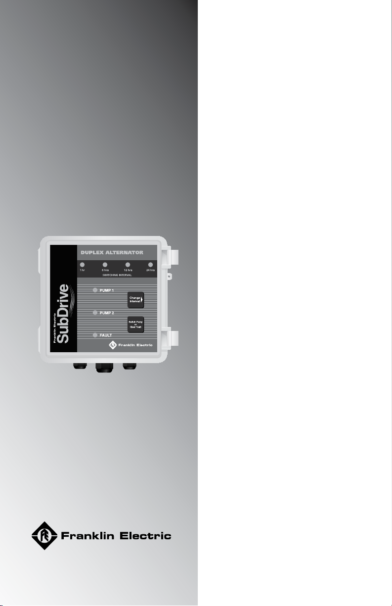
SubDrive Duplex Alternator
Fail Safe Operation
The Alternator is designed so that both SubDrive units are always linked to one
pressure sensor or the other. If the Alternator should fail, the system will turn into
a lead-lag system without the alternate function. Therefore, water will still
be delivered even if the Alternator should fail.
Additional Features
The Alternator has a manual override button for selecting which SubDrive unit
should be the primary system. The Alternator also has four different (push
button) selectable timing modes ranging from 1 hour to 24 hours. These timing
modes are based on the run time of the SubDrive unit. When a unit has run
the selected amount of time, the Alternator automatically interchanges the
primary and backup systems. In addition, the Alternator can be used with any
combination of SubDrive products from Franklin Electric; one model ts all!
s WARNING
!
For the indoor/outdoor transformer note the following:
Risk of fire. If installation involves running wiring through a building
structure, special wiring methods are needed. Consult a qualied electrician.
Not for use with dimmers.
Before Getting Started
s ATTENTION
!
This equipment should be installed by technically qualied personnel.
Installation must comply with Franklin Electric’s recommendations, national
and local electrical codes. Failure to do so may result in electrical shock,
re hazard, unsatisfactory performance, or equipment failure. Installation
information is available through pump manufacturers and distributors, or
directly from Franklin Electric at our toll-free number 1-800-348-2420.
s CAUTION
!
Use the SubDrive Duplex Alternator only with Franklin Electric SubDrive
units as specied in this manual (see Table 1). Use of this unit with Variable
Frequency Drives (VFDs) from other manufacturers may result in damage to
both sets of electronics.