Franklin Electric FHOTON User manual

Installation Guide
FHOTON AC/DC
Power Converter

Anytime working on or near the Fhoton AC/DC Power Converter, Fhoton Drive, or system:
• Securely cover the solar array with an opaque tarp.
• Turn OFF the external DC rated disconnect from the solar array to the Fhoton
drive controller.
• Wait a minimum of 5 minutes after removing power from the Fhoton Drive
before servicing.
IMPORTANT INFORMATION FOR INSTALLERS OF THIS EQUIPMENT!
THIS EQUIPMENT IS INTENDED FOR INSTALLATION BY TECHNICALLY QUALIFIED PERSONNEL.
FAILURE TO INSTALL IT IN COMPLIANCE WITH NATIONAL AND LOCAL ELECTRICAL CODES
AND WITHIN FRANKLIN ELECTRIC RECOMMENDATIONS, MAY RESULT IN ELECTRICAL
SHOCK OR FIRE HAZARD, UNSATISFACTORY PERFORMANCE, AND EQUIPMENT FAILURE.
FRANKLIN INSTALLATION INFORMATION IS AVAILABLE FROM PUMP MANUFACTURERS AND
DISTRIBUTORS AND DIRECTLY FROM FRANKLIN ELECTRIC.
ATTENTION
s WARNING
!
SERIOUS OR FATAL ELECTRICAL SHOCK MAY RESULT FROM FAILURE TO CONNECT THE MOTOR,
CONTROL ENCLOSURES, METAL PLUMBING, AND ALL OTHER METAL NEAR THE MOTOR OR
CABLE TO A PROPER EARTH GROUND IN ACCORDANCE WITH LOCAL CODES, USING WIRE NO
SMALLER THAN MOTOR CABLE WIRES. TO REDUCE RISK OF ELECTRICAL SHOCK, DISCONNECT
POWER BEFORE WORKING ON OR AROUND THE WATER SYSTEM. DO NOT USE MOTOR IN
SWIMMING AREAS.
s CAUTION
!
Use the Fhoton AC/DC Power Converter only with Fhoton Drive controllers up to 1.5HP (see
Specications page) and Franklin Electric motors as indicated in the Fhoton Drive controller
installation guide. Use of this unit with any other Franklin Electric motor or with motors from
other manufacturers may result in damage to both motor and electronics.
s WARNING
!
High voltages (both AC and DC) capable of causing severe injury or death by electrical shock
are present in this unit. More than one disconnect switch may be required to de-energize
the equipment before servicing. This unit should only be installed or serviced by technically
qualied professionals.
s WARNING
!
Solar panels that have been exposed to full solar insolation for an extended period of time
can achieve high temperatures and could be a potential source of burns to exposed skin if
contacted. Use caution when working around solar arrays.
2

3
Overview
The Fhoton™AC/DC Power Converter is an accessory for the Fhoton Drive that can convert AC
power sources to DC as needed by the Fhoton Drive. For installation guidelines refer to this
document along with the Fhoton Drive Installation Manual.
The Fhoton AC/DC Power Converter Accessory has a single-phase input power terminal block to
connect either a AC or DC power source and presents (converts) at its output terminals DC power
needed to power the Fhoton Drive.
The power source can either be an AC source, such as a generator or grid power, or a DC source,
such as an array of photovoltaic (PV) panels.
For information concerning the respective input voltage ranges, please refer to the specication
section located at the back of the manual.
Description
The power source connected to the input terminal block on the left side is directed to a full-wave
rectication circuit which converts AC to DC power. In the case of input AC power it is rectied to
DC power, and for input DC power it too is rectied so the output DC polarity is matching to the
polarity noted at the output terminal block. For this reason, the polarity of the power source at
the input terminal block is not polarity sensitive, so, is not marked with any polarity designation.
Additional circuitry in the AC/DC Power Converter limits the bus capacitor in-rush current at initial
power-up and protects the AC/DC Power Converter outputs from any situation where the output
is shorted. If a short circuit is detected the AC/DC Power Converter protects output connections
from large current spikes into a direct output attempting to protect the Fhoton Solar Drive from
receiving these potentially damaging short circuit surges. In this case a ashing Light Emitting
Diode (LED) will enunciate a Fault Code 6 fault indicating that there is a shorted condition in the
output wiring.
Reference the internal schematic showing the implementation of these functions located at the
end of this document.
The bicolor LED (green – for the running status; red for any fault code status) shines through the lid
as described further in the operational section and fault code section of the manual.
The controller construction is ruggedized for hostile environmental conditions.
• The case is constructed of heavy-gauge aluminum to resist rain, and animal intrusion.
• The seals are designed for Type 4 (IEC rating IP56), (withstands directed jets of water).
• For maximum protection against dust, there is no external cooling fan or other external
moving parts.
For use with specic Fhoton Drive Models
The Fhoton AC/DC Power Converter Model Number 581 114 204 is only to be used with the Franklin
Electric Fhoton Drives having model numbers 581013000XXX-X or 581014200XXX-X, with ratings of
up to, and including 1.5 hp. It is not to be used with Fhoton drives having ratings of 2 hp or higher,
or, with products made by other manufacturers.

4
Use of External Transfer Switches
The output of the Fhoton AC/DC Power Converter is to be connected directly to the input power
terminals of the noted Fhoton Drive Models. No other devices or connections should be combined
with the output connections.
There may at times be benet to switch between power sources, such as, from DC PV Panels to
AC Generator or back. In this case, any properly rated power switching device (transfer switch)
should be applied at the input to the AC/DC Power Converter, since the input terminals of the AC/
DC Power Converter are compatible with either AC or DC sources and will provide the benet of all
AC/DC Power Converter protection features.
If a transfer switch or disconnect is required, these devices should be connected on the input power
side of the AC/DC Power Converter. Connecting a transfer switch or disconnect between the AC/DC
Power Converter and Fhoton Solar Drive could result in nuisance trip/short circuit fault on the AC/
DC Power Converter. When applying electricity, the AC/DC Power Converter and Fhoton Solar Drive
should power on simultaneously.
Protection Features
Electronic monitoring gives the controller the capability to monitor the system and automatically
shut down in the event of (see page 8 for fault codes):
• Overvoltage
• Undervoltage
• Overload
• Short circuit
• Overheat
In a similar way, the controller incorporates circuitry that protects against:
• In-rush current control
• Surge protection (input and output)

5
Features
Flashing Green Light Run Mode and Solid Green Light Idle Mode
The Fhoton AC/DC Power Converter comes equipped with a bicolor LED indicator to convey
operational status to the user. When operating normally, the LED will indicate solid green (IDLE
condition) or ashing green (RUNNING condition). While in the RUNNING condition, the green
LED will ash indicating that the power is available at the output terminals of the AC/DC Power
Converter to power the Fhoton Drive.
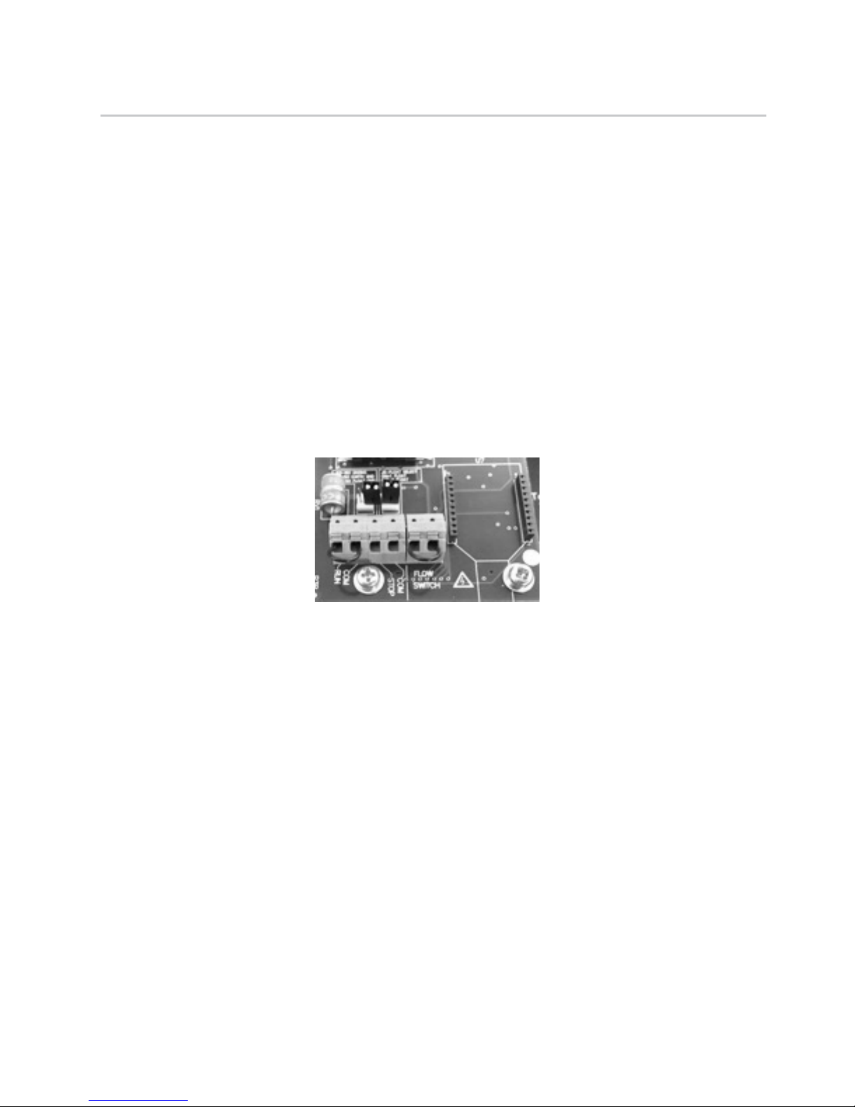
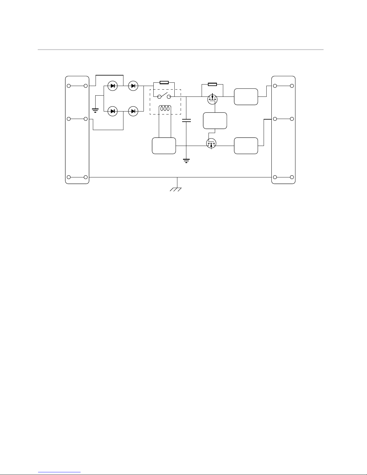
There are two factory installed jumpers connected to the User Interface Board (Figure 1): Run
Input and Flow Switch Input. If removed, the output of the Fhoton AC/DC Power Converter will
switch to a high impedance state disabling the Fhoton Drive. In this case, the LED will be solid
green indicating that it is in IDLE condition, awaiting to be enabled by reinstating the jumper.
This feature is provided in support of other accessories such as an auto transfer switch which will
connect to these inputs and allow for automatic switching between AC or DC sources. This can be
used by the user for additional control options.
The Fhoton AC/DC Power Converter continuously monitors system performance and can detect
a variety of abnormal conditions. In many cases, the controller will compensate as needed to
maintain continuous system operation; however, if a high risk of equipment damage exists,
the controller will protect the system and indicate the fault condition via a ashing red LED. If
possible, the controller will try to restart itself when the fault condition subsides (refer to the
troubleshooting section for a list of Fault Codes and correction actions).
The following sections detail the conditions in which a fault will occur.
Overvoltage (Single Flash Red LED Sequence)
The Fhoton AC/DC Power Converter continuously monitors the incoming power source voltage
for an overvoltage condition where if the voltage is greater than 420Vdc for a DC source, or
greater than 264 Vrms for a AC source, the AC/DC Power Converter output state will change to a
high impedance state to limit the output current. The red LED will begin a 1 ash sequence and
continue this ash sequence until the input voltage range is below the noted threshold where
normal operation will resume.
Undervoltage (Two Flash Red LED Sequence)
The Fhoton AC/DC Power Converter continuously monitors the incoming power source voltage for an
undervoltage condition where if the voltage is less than 45Vdc for a DC source, or 35Vrms for an AC
source, the AC/DC Power Converter output state will change to a high impedance state to limit the
output current being supplied to the Fhoton Solar drive. The red LED will begin a 2-ash sequence
and continue this ash sequence until the input voltage range is above the noted threshold where
normal operation will resume.
Figure 1
User Interface Board (Factory Installed Jumpers)

6
Output Over Load (Three Flash Red LED Sequence)
The Fhoton AC/DC Power Converter continuously monitors the output current. If the output
current exceeds the overload trip level the output state will change to a high impedance state to
limit the output current and the AC/DC Power Converter red LED will begin a 3-ash sequence
and continue this ash sequence for a two and half minute interval after which time, the AC/DC
Power Converter will resume normal operation. The longer off-time duration is provided to allow
the system to cool down and revert to a normal operating condition if the over load condition is
remedied.
Output Over Current, Short Circuit (Six Flash Red LED Sequence)
The Fhoton AC/DC Power Converter continuously monitors the output current. If the output
current exceeds the higher short circuit trip level the output state will change to a high impedance
state to limit the output current and the AC/DC Power Converter red LED will begin a 6-ash
sequence and continue this ash sequence for a two and half minute interval after which time, the
AC/DC Power Converter will resume normal operation. The longer off-time duration is provided
to allow the system to cool down and revert to a normal operating condition if the over current
condition is remedied.
NOTE: Integral solid state short circuit protection does not provide branch circuit protection.
Branch circuit protection must be provided in accordance with the National Electrical Code and any
additional local codes.
Over Temperature Shutdown (Seven Flash Red LED Sequence)
The Fhoton AC/DC Power Converter is designed for full power operation from a DC or AC power
source in ambient temperatures up to 122 °F (50 °C). Under extreme thermal conditions the AC/DC
Power Converter output state will change to a high impedance state to limit the output current.
The red LED will begin a 7-ash sequence and continue this ash until the internal temperature is
reduced. The output is restored when the AC/DC Power Converter temperature cools to a safe level
and a minimum of 10 minutes have passed by.
Internal Error (Nine Flash Red LED Sequence)
The Fhoton AC/DC Power Converter continuously monitors itself for potential, internal failures. If a
failure condition is detected, the Fhoton AC/DC Power Converter will change to a high impedance
state to limit the output current. The red LED will begin a 9-ash sequence and continue this ash
sequence until power is cycled.

7
Wiring Connections
1. Make sure that the external disconnect switch is off (Verifying that the power has been shut
off). Follow all safety warnings in this manual and in the Fhoton Drive Installation Guide.
2. Remove the Fhoton AC/DC Power Converter lid.
3. Use appropriate strain relief or conduit connectors. For Type 4 (IP 56), Type B liquid-tight
ttings are recommended for maximum weather protection. Must be provided in accordance
with all applicable national and local electrical codes.
4. Make the appropriate wiring connections in the following instructions and install per all
applicable local and national codes.
a. Select wire gauge, temperature rating (75 °C only, for the eld installed conductors) based
on code recommendations for the maximum operating currents listed in the specication
section. Ensure that any protection devices, such as fuses or circuit breakers, are appropriately
sized and installed per local and national code.
5. Make sure that all wires are properly identied and marked.
6. Connect the cables from the external DC disconnect to the left Fhoton AC/DC Power
Converter input terminal block labeled “AC or DC”. (Torque specication: 15 in-lbs/ 1.7 N-m.)
(Only use copper conductors rate 75 °C minimum.) The input wire length from the power
source shall not exceed 300 ft (100 m). Note: The Fhoton AC/DC Power Converter input is not
polarity sensitive.
7. Connect the cable from the output of the Fhoton AC/DC Power Converter to the input of the
Fhoton Drive making sure to match the polarity designation as shown in the gure below.
(Torque specication: 15 in-lbs/ 1.7 N-m). (Use copper conductors only. Rated 75 °C minimum.)
The output cabling to the Fhoton Drive shall not exceed 30 ft (10 m). Note: The Fhoton AC/DC
Power Converter output is polarity sensitive.
8. Ground wire shall be insulated; typically green or green with yellow stripe.
9. Review the wiring that it matches the wiring diagram below for the Fhoton AC/DC Power
Converter and Fhoton Drive
10. Replace the cover. Do not over-tighten the screws.
a. Torque screws to 6 in-lbs. (0.68 Nm).
NOTE: Ensure that the system is properly grounded. Improper grounding may result in the loss of
voltage surge protection and interference ltering.
Directly to Fhoton Drive
(Match Polarity)
From
Disconnect
(AC or DC)
Input Is Not
Polarity
Sensitive
Fhoton
AC/DC Power
Connecter
Fhoton Drive
Input OutputInput Output
To Motor

8
Fault Codes and Troubleshooting
The Fhoton AC/DC Power Converter will attempt to power the Fhoton Drive to deliver water
even under adverse conditions. To ensure years of reliable service, it must also protect the system
components from conditions that might result in equipment damage. Full operation will resume
automatically whenever abnormal conditions subside.
Error conditions may suspend certain features or shut down operation of the system for varying
amounts of time depending on the nature and severity of the error. Problems that reduce
performance generally restore full operation when the trouble condition subsides. An error code is
displayed by the ashing red LED light.
If the Fhoton AC/DC Power Converter has stopped to indicate a fault code, the associated time-out
delay will vary depending on the nature of the fault.
Fault
Code
Fault Possible Causes Corrective Action
1 Overvoltage
The incoming power source has a
voltage greater than the specied
input rating
Ensure the input power wiring is correct
and powered from a source that has
a nominal voltage rating within the
specied input voltage range
2 Undervoltage
The incoming power source has
a voltage less than the specied
input range
The available power may not be sufcient
to supply the minimum voltage range.
Check the capability of the incoming
power source.
3 Over load
The output of the AC/DC Power
Converter has a load greater than
the specication
Check the condition of the power cable
between the AC/DC Power Converter and
the Fhoton Drive and the cable connections
4 None Not applicable Not applicable
5 None Not applicable Not applicable
6 Short Circuit
Short in connections between the
AC/DC Power Converter Output and
the Fhoton Drive Input
Check the condition of the power cable
between the AC/DC Power Converter and
the Fhoton Drive and the cable connections
7 Overheated Controller
Unit in direct sunlight.
High ambient temperature.
Shade unit.
Clean any debris from heat sink ns on
rear of enclosure.
This fault automatically resets when
temperature returns to safe level.
8 None Not applicable Not applicable
9 Internal Error Controller internal processing has
encountered an incorrect value.
Cycle input power. Disconnect incoming
power source for at least ve minutes,
then re-connect power.

9
AC/DC Power Converter Specications
The AC/DC Power Converter can accept either AC or DC input power (Polarity Independent), and the
output is DC, where the polarity is denoted by a “+” and a “-“ symbol.
AC/DC Power Converter Model No. 581114204
Input AC or DC
Phase Single (Polarity Independent)
Voltage (AC Power Source)
90Vrms to 264Vrms, 50Hz or 60Hz
• Use 120Vac when 3/4Hp System
• Use 240Vac when 1.5Hp System
Voltage (DC Power Source) 45Vdc to 420Vdc
Current (AC Power Source)
14.9Arms, Max
(Suitable for use on a circuit capable
of delivering not more than 5,000rms
symmetrical amperes, 420VDC or
264VAC Maximum)
Current (DC Power Source) 10Adc, Max
Power Factor From AC Power Source 0.65 (Approx. - Rectier Input)
Output DC
Phase Single (Polarity is noted)
Voltage (Rectied Output) 45Vdc to 420 Vdc
Current 7.5Adc, Max
Overload Trip Level 10Adc
Short Circuit Trip Level 40A
Efciency at Max Power 98%
Use with these Franklin Electric
Fhoton Drive Models, only
Models 58101300 or 58101420 followed
by any sequence of numbers or
characters up to and including 1.5 hp
Controller Size L x W x D
Millimeters 159.5 x 159.5 x 185.8
Inches 6.28 x 6.28 x 7.32
Operating Conditions
Temperature Range -25 °C to 50 °C Max.
-13 °F to 122 °F Max.
Relative Humidity Range 0 to 100% Condensing
Enclosure Type UL Type 4 rating (IEC IP56 rating)

10
AC/DC Power Converter Schematic
The power source connected to the input terminal block on the left side is directed to a full-wave
rectication circuit which converts AC to DC power. In the case of input AC power it is rectied to DC
power, and for input DC power it too is rectied so the output DC polarity is matching to the polarity
noted at the output terminal block. For this reason, the polarity of the power source at the input
terminal block is not polarity sensitive, so, is not marked with any polarity designation.
There is additional circuitry in the AC/DC Power Converter that limits the bus capacitor in-rush current
at initial power-up and protects the AC/DC Power Converter outputs from any situation where the
output is shorted. If a short circuit is detected the AC/DC Power Converter output connections will go
to a high impedance state to avoid sourcing large currents into a direct output short-circuit. In this
case a ashing Light Emitting Diode (LED) will enunciate a Fault Code 6 fault indicating that there is a
shorted condition in the output wiring.
Circuit Operation
AC OR DC
VOLTAGE INPUT
DC VOLTAGE
OUTPUT TO
FHOTON DRIVE
D D
D D
R
C
Q
Q
R
EARTH
CHASSIS EARTH
EARTH
CONTROL
CIRCUIT
CONTROL
CIRCUIT
CURRENT
SENSOR
CURRENT
SENSOR
INPUT
TERMINAL
BLOCK
OUTPUT
TERMINAL
BLOCK

11
AC/DC Power Converter Outline Dimensions
AC/DC Power
Converter
Dimensions
A B C D E F G.1* G.2 G.3 G.4 G.5
Inches 8.17 6.28 6.10 4.88 7.40 6.28 7.32 3.30 1.38 1.38 4.94
Millimeters 207.55 159.4 155 124 188 159.4 185.82 83.82 35 35 125.47
F
BDC
E
A
G.2
G.1
G.3
G.4
G.5

9255 Coverdale Road, Fort Wayne, IN 46809
Tel: 260.824.2900 Fax: 260.824.2909
www.franklinwater.com
FE USA Technical Service Hotline
1.800.348.2420
224455101
Rev. 1
03.18
Other manuals for FHOTON
1
Table of contents
Popular Media Converter manuals by other brands

Space Television
Space Television PT-100 manual

AJA
AJA R44E Installation and operation guide

Phoenix
Phoenix PSM-ME-RS232/RS485-P Installation notes for electricians

Audio Note
Audio Note DAC5 Special Owner's Information

American Dynamics
American Dynamics VideoEdge Architect & engineer Specification

PRIZM
PRIZM 201350 Series User's manual and troubleshooting guide