Franklin Fueling Systems FE PETRO PMA 75 Guide

©2013 400289002 Rev. 9
Franklin Fueling Systems •3760 Marsh Rd. • Madison WI 53718 USA
Tel: +1 608 838 8786 • 800 225 9787 • Fax: +1 608 838 6433 •www.franklinfueling.com
Pump Motor Assembly
Replacement Instructions

2
Important Safety Messages
FE Petro equipment is designed to be installed in association with volatile hydrocarbon liquids such as gasoline and
diesel fuel. Installing or working on this equipment means working in an environment in which these highly flammable
liquids may be present. Working in such a hazardous environment presents a risk of severe injury or death if these
instructions and standard industry practices are not followed. Read and follow all instructions thoroughly before
installing or working on this, or any other related equipment.
As you read this guide, please be aware of the following symbols and their meanings:
Follow all applicable codes governing the installation and servicing of this product and the entire
system. Always lock out and tag electrical circuit breakers while installing or servicing this
equipment and related equipment. A potentially lethal electrical shock hazard and the possibility
of an explosion or fire from a spark can result if the electrical circuit breakers are accidentally
turned on during installation or servicing. Do not smoke while working on or near this equipment,
and use only non-sparking tools.
Before entering a containment sump, check for the presence of hydrocarbon vapors. If these
vapors are inhaled they could cause dizziness or unconsciousness, and, if ignited, hydrocarbon
vapors could explode causing serious injury or death. Electronic and electrical petroleum
monitoring equipment is often housed in containment sumps designed to trap hazardous liquid
spills and prevent contamination of the environment, and, as a consequence, containment sumps
can trap dangerous amounts of hydrocarbon vapors. If these vapor levels reach unsafe amounts,
ventilate the sump with fresh air. While working in the sump, periodically check the atmosphere
in the sump, if vapors reach unsafe levels, exit the sump and ventilate it before continuing work.
Always have a second person standing by for assistance when working in, or around, a
containment sump.
Follow all federal, state, and local laws governing the installation of this product and its
associated systems. When no other regulations apply, follow NFPA codes 30, 30A, and 70 from
the National Fire Protection Association. Failure to follow these codes could result in severe
injury, death, serious property damage, and/or environmental contamination.
Always secure the work area from moving vehicles. The equipment in this manual is usually
mounted underground, so reduced visibility puts service personnel working on this equipment in
danger from moving vehicles entering the work area. To help eliminate these unsafe conditions,
secure the area by using a service truck to block access to the work environment, or by using any
other reasonable means available to ensure the safety of service personnel.
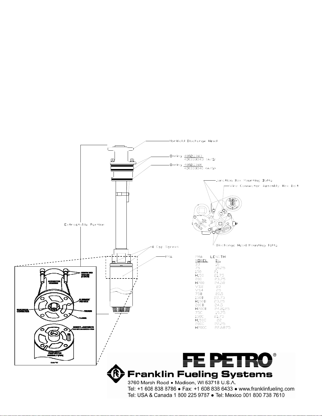
FE Petro’s PMAs are designed for use with motor fuels and are UL listed for blend concentrations of:
Standard Models AG (Alcohol/Gasoline) Models
0% - 10% ethanol with gasoline 0% - 85% ethanol with gasoline
20% MTBE with 80% gasoline 20% MTBE with 80% gasoline
20% ETBE with 80% gasoline 20% ETBE with 80% gasoline
17% TAME with 83% gasoline 17% TAME with 83% gasoline
100% Diesel 0-20% Biodiesel Blend or 100% Biodiesel
Other motor fuels that may be used with the PMA are diesel, fuel oil, avgas, jet fuel, or kerosene.
The maximum liquid viscosity for a product is 70 S.S.U. at 60° F.
Using our PMA in liquids other than those mentioned above has not been tested. The reaction of
other liquids with seals and wetted surfaces of the pump is unknown. A hazardous situation may
result from using other liquids with our pump.
Note: Schedule 40 riser pipe will not work with our MagShell™ PMAs because of an enlarged outside diameter
(4.050"). Our standard shell PMAs have a maximum outside diameter of 4.014" (3.922" for AG models).
This symbol identifies a warning. A warning sign will appear in the text of this document when a
potentially hazardous situation may arise if the instructions that follow are not adhered to closely.
A
potentially hazardous situation may involve the possibility of severe bodily harm or even death.
This is a caution symbol. A caution sign will appear in the text of this document when a potentially
hazardous environmental situation may arise if the instructions that follow are not adhered to closely.
A
potentially hazardous environmental situation may involve the leakage of fuel from equipment that
could severel
y
harm the environment.
Warning
Warning
Warning
Warning
Caution
Warning
Warning

3
Procedure
1. Disconnect power to the submersible pump at the electrical supply box.
2. Tag and lock out electrical circuit breakers so they are not turned on accidentally.
Note: See Figure 1 to identify the particulars of a STP.
3. Loosen the two junction box mounting bolts, but don’t remove them. This will make disconnecting the wire
connector assembly easier.
4. Carefully disconnect the wire connector assembly, by backing out the hex head bolt and swinging the wire connector
assembly aside (see Figure 1).
5. Remove the two discharge head mounting bolts, which hold down the discharge head.
6. Using a hoist, carefully lift the extractable portion of the pump from the tank, being careful not to jam the PMA
against the bottom of the riser on the way out. Lay the assembly down.
7. Using a 1/4 inch hex key, remove the four cap screws and washers. Using a rocking motion, remove the old PMA
and discard the old flange joint gasket, cap screws, and washers. Inspect flange surface, recess wall, and electrical
connector. Make sure that they are clean and undamaged. DO NOT assemble the new PMA to a damaged flange!
8. Measure and compare the length of the old PMA with the new PMA. Make certain after installing new PMA there will
be 4 to 5 inches clearance between the bottom of the PMA and the tank for best operation. Figure 1 shows a list of
PMA models with length.
9. Verify proper capacitor for new PMA from table below. The new PMA may require the installation of a different size
capacitor (3 phase models do not use capacitors).
PMA Model Capacitor Voltage Rating
33, 75 15 to 17.5 μF 370 V (Minimum)
150, H150 15 to 25 μF 370 V (Minimum)
200, H200 40 to 50 μF 370 V (Minimum)
VS2, VS4, 75C, 150C, H150C, 200C, H200C None None
75B 15 to 17.5 μF 440 V (Minimum)
150B, H150B 15 to 25 μF 440 V (Minimum)
200B, H200B 40 to 50 μF 440 V (Minimum)
* 4 screws, 4 washers, a flange gasket, and a pack of grease are included along with these instructions.
10. Remove the 4 cap screws and washers from the new PMA kit, leaving the new gasket in place on the PMA.
Note: Be sure the new gasket is used, because the gasket on some competitive PMA’s will block the flow of product
through the motor. This blockage will prevent proper cooling and lubrication of the motor and bearings, and lead
to shorter motor life.
11. Apply grease (from the small grease tube provided) to the mating pieces on the PMA and the motor discharge head
casting, to make assembly easier. If the supplied grease tube isn’t used, DO NOT use a conductive lubricant (i.e.
Anti-seize) because this would cause a direct short and motor failure.
12. Align the positioning dowel of the new PMA into the hole in the motor discharge head casting, and make sure that
the metal and gasket surfaces are free of any dirt or foreign particles, carefully push (using hand force only) the
new PMA with the new gasket as far as possible against the discharge casting. If hand force will not close the
gasket joint, determine and correct the cause. Do not alter the metal recess or nose diameters, or use screws to pull
into place.
13. Assemble a new screw with a lockwasher finger-tight in each mounting hole, then gradually tighten all screws in a
cross pattern until all are tightened at 6-7 foot-pounds torque.
Note: Failure to push the PMA up snug against the discharge casting prior to tightening the cap screws, or failure to use
a cross-pattern while tightening the bolts could break the discharge casting or strip the threads in the PMA.
14. Apply a multi-purpose grease to the three o-rings on the manifold discharge head. Make sure that any sand or
gravel that might have been picked up on the entire unit is cleaned off, and using a hoist, reinstall the extractable
portion of the pump.
15. Replace the hex head cap screws in the discharge head and finger-tighten. Be sure the discharge head is down
flush on the manifold.
16. Reconnect the wire connector assembly and tighten the hex head bolt.
17. Tighten hex head cap screws in the discharge head, and junction box mounting bolts to approximately 30 foot-
pounds.
18. Follow system manufacturer instructions to reassemble the system.

©2013 FFS 400289002 Rev. 9
19. Connect power to the submersible pump at the electrical supply box.
20. Test proper operation by dispensing product into calibration can.
21. Turn off the dispenser switch. Feel the submersible pump, to make sure that the pump has stopped running.
Note: If the pump does not turn off when the dispenser switch is turned off, this may indicate an electrical problem in the
dispenser or other wiring error or malfunction. Call this to the immediate attention of a qualified electrician.
22. Visually check for leaks on the manifold head during pump operation and after.
23. To ensure that the STP is providing proper line pressure, install a pressure gauge in the line test port. Turn on the
STP and, while it’s running, the pressure should be above 24 psi (1.65 bar) (PMA size will affect psi). Turn off the
STP and verify that the line pressure is holding. Remove the pressure gauge, replace the plug, turn on the STP and,
again, visually check for any leaks.
24. If any leaks are observed, line pressure isn’t correct, or any other problems or concerns occur, call FFS Technical
Support at 1-800-225-9787.
25. Fill out the Warranty Registration Card and return it to Franklin Fueling Systems.
Note: If a STP or an IST does not operate correctly or there are any questions concerning installation or service, please
contact FFS Technical Services at (800) 225-9787.
This manual suits for next models
17
Table of contents
Popular Water Pump manuals by other brands

ETATRON D.S.
ETATRON D.S. eOne PLUS Operating instructions and maintenance

Graco
Graco EGP 25T817 instruction manual

GORMAN-RUPP
GORMAN-RUPP PA6C60-4045T-ESP Installation, operation and maintenance manual

Zyno Medical
Zyno Medical Z-800 Instructions for use

variolux
variolux V-GP 900 operating instructions

TOHATSU
TOHATSU VC52AS owner's manual

Pentair
Pentair S1800V-03 installation instructions

Whale
Whale Gusher 30 Series Installation & user's instructions

Flotec
Flotec FPZT7300 owner's manual

Whale
Whale Orca 500 Installation and operation manual

Barnes
Barnes 3SCM Installation and operation manual

Jesco
Jesco EASYDOS Peristaltic V Operating & Maintenance Instruction