Franklin Water Treatment SWS1 Series Quick start guide

Franklin Water Treatment, LLC.
12630 US Highway 33 N
Churubusco, IN 46723
Phone (260) 693-1972 Fax (260) 693-0602
SWS1 Series Instruction Manual 230123AF.docx
SWS1 Series
Water Softening System
Installation Instructions and Owner’s Manual

1
Pre-installation Instructions
Page 3
Detailed Installation
Page 5
Brine Tank Components
Page 6
Bypass Valve Operation
Page 7
General Operation & Set Time of Day
Page 8
Installer Settings & Regeneration Display
Page 9
Manual Regeneration
Page 10
Specifications
Page 11
Component Parts Breakdown & List
Page 12
Control Valve Exploded Parts Diagram
Page 13
Control Valve Parts List
Page 14
Installation Fitting Assemblies
Page 15
Troubleshooting
Page 18
Ten Year Limited Warranty
Page 21
Table of Contents

2
This page intentionally left blank

3
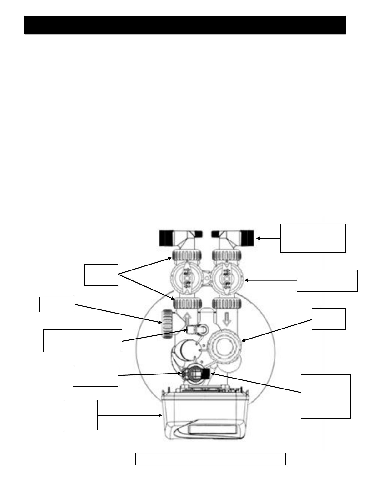
Description of the water softener system
This water softener system includes a brine (salt) tank and a resin (media) tank with a backwashing control
valve. Incoming water flows into the control valve and is directed down through the ion exchange softening
resin. This resin exchanges the hardness ions for softer ions. The softened water then returns to the control
valve where it is directed into the service lines.
Periodically the control valve will go through a regeneration cycle. The frequency of this regeneration process
will depend on the size of water softener, incoming water quality and amount of water used. This cycle is
factory preset to begin at 2:00 A.M. At this time the control valve will backwash, draw the brine solution out of
the salt tank and flush both the accumulated hardness and excess salt to the drain, followed by a rinse. Prior to
the next regeneration cycle the softener will put water back into the brine tank and allow it to dissolve salt for the
regeneration.
Water Quality
The water should be tested to determine the concentration, or levels of the items listed below:
Hardness - Hardness in drinking water is defined as those minerals that dissolve in water having a
positive electrical charge (cat ions). The primary components of hardness are calcium (Ca++) and
magnesium (Mg++) ions. But dissolved iron (Fe++) and manganese (Mn++) also contribute to total
“adjusted” hardness.Hardness produces scale, soap scum and white mineral deposits which shorten
the life of water using appliances, plumbing and fixtures. Water that has less than 1 grain of hardness is
considered “soft” water.
pH - A measurement of the acidity of the water. pH is reported on a scale from 0 to 14. Neutral water has a pH
of 7.0, lower values indicate acidic water. If your pH is below 6.8 you may consider installing an acid neutralizer
before the water softener to elevate the pH.
Iron - A naturally occurring metallic element. Iron levels in excess of 0.3 milligrams/liter (mg/l) combine with
oxygen causing orange or red (rust) stains on plumbing fixtures. Iron exists in some water sources in clear
water (ferrous) state, red water (ferric) state or bacterial form. Iron levels that exceed 2.0 mg/l require special
ion exchange resin for reduction, or if bacterial or ferric (red water) iron is present or iron level exceeds 3.0 mg/l,
an iron filter should be installed ahead of this water softener.
Manganese - A naturally occurring metallic element. Manganese levels as low as 0.05 milligrams/liter (mg/l)
can combine with oxygen to cause dark brown or black staining on fixtures. Additionally, manganese can cause
an odor in the water similar to a “rotten egg” smell. This water softener may reduce manganese as well as iron;
however, an iron filter may be required in some cases.
Tannin - A naturally occurring humic acid. Tannin is caused by water passing through decaying vegetation.
Coffee and Tea are prime examples of tannin in water. Tannin levels as low as 0.5 milligrams per liter can
cause a yellow discoloration in water. Consult your dealer for a system designed to remove both tannin and
hardness.
Hydrogen Sulfide - A naturally occurring gas. Hydrogen sulfide, more commonly referred to as sulfur gas,
causes a distinct odor similar to “rotten eggs.” Due to its gaseous nature, hydrogen sulfide must be tested at the
well site within 1 minute of drawing the sample. If sulfur is present additional equipment will be required. Air
injection iron filters can typically treat up to 2 ppm of sulfur gas if regenerated daily. Specialized filter media may
reduce sulfur up to 6 ppm. Beyond 6 ppm and up to 10 ppm require chemical injection. Beyond 10 ppm may
be impractical to treat.
Pre-installation Instructions

4
Location Considerations
The proper location to install the water softener system will ensure optimum performance and satisfactory water
quality. The following factors should be considered in selecting the location of the equipment.
1. The water softener should be installed after the pressure tank on a private well system or after the
water meter on municipal water. Operating pressure of the softener must be limited to within 30 –
100 psi range.
2. The water softener should be installed as close as possible (preferably within 15’) to an adequate
floor or laundry drain capable of handling the backwash cycle volume and flow rate (refer to unit
specifications).
3. All water conditioning equipment should be installed prior to the water heater. Water temperatures
exceeding 100°F can damage the internal components of the control valve and filter tank. Install
with at least 10’ of pipe before the water heater to prevent thermal damage to the equipment. An
expansion tank may need to be installed in the line to the water heater to allow for thermal
expansion and comply with local plumbing codes.
4. The water softener should not be subject to freezing temperatures.
5. Ensure that any cartridge or in-line type filter installed prior to the water softener does not restrict
the water flow and pressure available for backwash and interfere with normal operation.
6. Appliances requiring extended periods of continuous or high flow water use (i.e. geothermal heat
pumps, swimming pools, lawn irrigation, outside hose bibs, etc.) should bypass the water softener.
(see installation diagram Fig. 1).
Water Heater
Inlet from
water
supply
Softened
Cold Water
Iron Free Water
Softened
Hot Water
Untreated Water
Water Softener
Iron Filter
(if required)
Pressure Tank
(well system only)
10’ Minimum Distance
Grounding Straps
Pre-installation Instructions (cont.)
FIGURE 1: Typical Installation
Cartridge
Filter
Expansion
Tank

5
STEP 1: Carefully remove all components from packaging. DO NOT DISCARD PACKAGING until all
water softener components and fittings have been located.
STEP 2: Using the integrated coupling nuts, attach the bypass valve to the inlet/outlet of the control
valve and put handles in the bypass position (Figure 2).
STEP 3: Place unit at desired installation position.
STEP 4: Shut off water at main supply. Relieve pressure by opening nearest faucet. On private well
systems, turn off power to pump and drain pressure tank. SHUT OFF POWER OR FUEL
SUPPLY TO WATER HEATER.
STEP 5: Cut main supply line as required to fit plumbing to inlet and outlet of bypass valve. DO NOT
PLUMB INLET AND OUTLET BACKWARDS. Piping should be supported. Do not apply heat
to any fitting attached to the bypass or control valve.
STEP 6: Use the provided polyethylene tubing (NO VINYL TUBING) to run drain line from control valve
drain fitting (Figure 2) to floor drain or sump pit capable of handling the backwash rate of the
softener (refer to specifications on Page 11). THE DISCHARGE END OF THE DRAIN LINE
MUST BE FIRMLY SECURED! There must be an air gap at the end of the drain line to
prevent siphoning of wastewater and meet plumbing code. Total length of drain line should be
15’ or less. AVOID OVERHEAD DRAINS.
Detailed Installation Instructions
FIGURE 2: Top View of Control Valve
Meter
Union
Nuts
Plumbing Adapter 1”
MNPT Elbows
Included
Bypass Valve
(in service position)
Brine Refill Elbow
(Retainer Clip Not Shown)
Drain Fitting,
3/4” MNPT
(Compression
fitting not
shown)
Injector
Housing
Control
Valve
Cover
Drain Fitting
Retainer Clip

6
STEP 7: Connect one end of the 3/8” brine line to the control valve quick connect brine refill elbow
(Figure 2, Page 5). Insert the other end of the brine line through the hole in the brine tank and
into the quick connect fitting on the top of the safety brine valve (Figure 3). Remove the quick
connect collet retainer clip (if included) before inserting the brine line into each fitting, press the
tube in very firmly and replace the retainer clip behind the collet. NOTE: THE BRINE TUBING
SHOULD BE INSERTED 5/8” INTO THE FITTING. DO NOT PUT SALT INTO THE BRINE
TANK AT THIS TIME.
STEP 8: If desired, install overflow tubing (not provided) from overflow elbow on brine tank (Figure 3) to
floor drain. Tubing must be lower than the overflow elbow at all times. DO NOT CONNECT
DRAIN LINE FROM SOFTENER CONTROL VALVE TO BRINE TANK OVERFLOW. DO
NOT CONNECT BRINE TANK DRAIN LINE TO THE SOFTENER DRAIN LINE.
STEP 9: Plug the transformer into an un-switched electrical outlet. Ensure the control valve is in
“Service” mode (time of day is displayed on the screen {refer to page 8 for Home Screen
Display}).
STEP 10: Place the bypass valve in the “Service” position (refer to Figure 2, Page 5; Figure 4, Page 7)
and open main supply valve or turn on power to pump on private well systems. Allow the unit
to fill with water and pressurize, then place the bypass valve in the “Bypass” position.
STEP 11: Add water in the brine tank to slightly above the top level of the salt grid (approx. 6 gallons).
DO NOT ADD SALT TO THE BRINE TANK AT THIS TIME.
FIGURE 3: Brine Tank Components
Detailed Installation Instructions (continued)
Insert brine tube into quick
connect fitting
Remove brine tube
from quick connect
fitting
Insert brine
tubing here
through
hole in brine
tank shell
Safety
Brine Valve
Assembly
Brine
Tank Lid
Brine Well
Lid
Brine Well
Salt Grid
Overflow
Elbow
Brine Tank
Shell

7
STEP 12: With the bypass valve in the “Bypass” position (refer to Figure 2, Page 5; Figure 4, Page 7),
press and hold the REGEN button until the motor starts. Then use the REGEN button to
advance the control valve to the BACKWASH cycle (refer to page 10 for details) to release
pressure and purge air from the mineral tank.
STEP 13: Refer to Figure 4 bypass valve operation. Rotate the INLET knob of the bypass valve slowly
to the “Service”position. If any air spurts or any softener resin is expelled to the drain, stop
turning the knob until only water flows to the drain, then continue turning the knob fully to the
“Service” position.
STEP 14: When all air has been purged from the system and only water is running to the drain, turn the
OUTLET knob of the bypass valve to the “Service” position also. Allow the system to
backwash for a few minutes or until the drain water runs clear.
STEP 15: Using the REGEN button, advance the control valve to the BRINE DN (downflow brine draw)
cycle. Verify that the water level in the brine tank is slowly dropping (less than ½ gpm). Allow
water level to drop below the top of the salt grid before continuing. If the water level does not
drop, refer to page 18 for Troubleshooting. After verifying water level is dropping advance the
control valve past the BACKWASH 2, RINSE AND 5 second FILL cycle to the time of day,
using the REGEN button.
ADD SALT TO BRINE TANK NOW. Any type of water softener salt may be used.
STEP 16: Check for leaks and correct as necessary.
STEP 17: Turn power or fuel supply back on to water heater.
STEP 18: Press and hold the NEXT and UP buttons together until the screen changes to input the
adjusted hardness level water (refer to Installer Settings, Page 9, for details), then press NEXT
repeatedly until the time of day is displayed.
STEP 19: Press the CLOCK button to set the current time of day. (Page 8, note AM and PM).
FIGURE 4: Bypass Valve Operation
Detailed Installation Instructions (continued)

8
General Operation
Set Time of Day
When the system is operating one of two
displays will be shown. Pressing NEXT
will alternate between the displays. One
of the displays is always the current time
of day. The second display is gallons
remaining. This is the number of gallons
that can be treated before the system
needs to go through a regeneration
cycle.
The user can scroll between the displays
as desired. If the system has called for a
regeneration that will occur at the preset
time of regeneration, the words “REGEN
TODAY” will appear on the display.
When water is being treated (i.e. water is
flowing through the system) the word
“SOFTENING” flashes on the display.
Step 1 - Press CLOCK.
Step 2 - Current Time (hour): Set the
hour of the day using ▲or ▼buttons.
AM/ PM toggles after 12. Press NEXT to
go to step 3.
Step 3 - Current Time (minutes): Set the
minutes ofday using ▲or ▼buttons.
Press NEXT to exit Clock. Press REGEN
to return to previous step.
Power Loss - Lithium battery on circuit
board provides up to 8 hours of time
clock backup during power outages.
After 8 hours, only the time of day needs
to be reset, all other values are stored in
non-volatile memory. If a power loss last
less than 8 hours and time of day is
flashing, replace coin type 2032 battery.
Do not forget to reset for daylight savings
time

9
Installer Settings
Regeneration Display
Step 1 - Press NEXT and ▲simultaneously for 3 seconds.
Step 2 - Hardness: Set the amount of adjusted hardness in
grains per gallon (hardness gpg + (iron ppm x 3) +
(manganese ppm x 5)) using ▲or ▼buttons. The default is
20 with value ranges from 1 to 150 in 1 grain increments. If
this display shows “nA –“, then system is either set-up in
“time clock” or “filter” modes. Press NEXT to go to Step 3.
Press REGEN to exit Installer Settings.
Step 3 - Day Override: This sets the maximum number of
days between regenerations. If value set to “oFF”
regeneration is initiated automatically solely on gallons used.
If value is set as a number (allowable range from 1 to 28) a
regeneration will be initiated automatically on that day even if
metered gallon usage does not trigger a regeneration. Press
NEXT to go to step 4. Press REGEN to return to previous
step.
Step 4 - Regeneration Time (hour): Set the hour of day for
regeneration using ▲or ▼buttons. AM/PM toggles after 12.
The default time is 2:00 a.m. This display will show “REGEN”
on 0 GAL if system is set for immediate regeneration. Press
NEXT to go to step 5. Press REGEN to return to previous
step.
Step 5 - Regeneration Time (minutes): Set the minutes for
the regeneration time using ▲or ▼buttons. This display will
not be shown if system is set for immediate regeneration.
Press NEXT to exit Installer Displays/Settings. Press REGEN
to return to previous step.
Typically, a system is set to regenerate at a time of low water usage. An
example of a time with low water usage is when the household is asleep. If
there is a demand for water when the system is regenerating, untreated
water will be supplied. When the system begins to regenerate, the display
will change to include information about the step of the regeneration process
and the time remaining for that step to be completed. The system runs
through the steps automatically and will reset itself to provide treated water
when the regeneration has been completed.

10
Manual Regeneration
Sometimes there is a need to regenerate the system, sooner than when
the system calls for it, usually referred to as manual regeneration. There
may be a period of heavy water usage because of guests or a heavy
laundry day.
To initiate a manual regeneration at the preset delayed regeneration
time, press and release REGEN. The words “REGEN TODAY” will flash
on the display to indicate that the system will regenerate at the preset
delayed regeneration time. If you pressed the REGEN button in error,
pressing the button again will cancel the request.
To initiate a manual regeneration immediately, press and hold the
REGEN button for three seconds. The system will begin to regenerate
immediately. The request cannot be cancelled. You must cycle all the way
through the cycles to make it stop. PLEASE NOTE: This will reset the
meter. If back-to-back regenerations aredesired, press and release
REGEN button. "REGEN TODAY" will appear on screen. Push and hold
REGEN button to initiate immediate regeneration. The softener will
regenerate again at specified time. Back-to-back regenerations are
recommended when salt is allowed to run out in brine tank. Note: If the
brine tank does not contain salt, fill with salt and wait at least 90 minutes
before regenerating

11
Description
Two Tank Models
Cabinet Models
Space
Saver
Model
SWS1-0948
SWS1-1054
SWS1-1248
SWS1-1354
SCCWS1-1035
SCCWS1-1044
SWS1C-1035
Resin Volume ft3
1.0
1.5
2.0
2.5
1.0
1.3
1.0
Capacity, grains
@Factory Salt
24,000
36,000
48,000
60,000
24,000
32,000
24,000
@Max. Salt @ 15lb/ft3
30,000
45,000
60,000
75,000
30,000
39,000
30,000
Gravel Underbed, lbs
15
20
25
30
20
20
20
Operating Flow Rate, gpm
Continuous (3 gpm/ft3)
3
5
5
8
3
4
3
Service (<=8 gpm/ft3, <15psi drop)
8
12
14
18
8
10
8
Peak (<20 psi drop)
18
18
23
22
22
19
22
Regen. Flow Rates, gpm
Backwash & Rapid Rinse
2.2
2.7
3.2
4.2
2.7
2.7
2.7
Injector
Blue
Blue
Blue
Yellow
Blue
Blue
Blue
Brine Draw - Rinse ( @ 50 psi)
0.38-0.5
0.38-0.5
0.38-0.5
0.43-0.64
0.38-0.5
0.38-0.5
0.38-0.5
Service Pipe Size, in.
1”
1”
1”
1”
1”
1”
1”
Factory Regeneration Settings
Brine Tank Fill (lbs of salt)
9
13.5
18
22.5
9
12
9
Softening (minutes dissolving salt)
120
120
120
120
120
120
120
P Code
P7
P11
P12
P12
P7
P7
P7
Backwash (minutes)
6
7
7
7
6
6
6
Brine Draw & Rinse (minutes)
45
60
65
65
45
45
45
Backwash 2 (minutes)
4
6
7
7
4
4
4
Rapid Rinse (minutes)
3
6
7
7
3
3
3
Total Water Used, gallons
53
84
104
133
60
61
60
Dimensions (inches)
Mineral Tank, diameter x height
9x48
10x54
12x48
13x54
10x35
10x44
10x35
Brine Tank, width x depth x height
18x18x33
18x18x33
18x18x33
18x18x33
-NA-
-NA-
12X12X34
Overall, depth x width x height:
18x27x56
18x28x62
18x30x56
18x31x62
12x24x45
12x24x50
16x23x43
Approximate Ship Wt., lbs.
104
137
162
213
105
135
94
Description
HE Two Tank Models
HE Space
Saver Model
SWS1-1035-HE
SWS1-1054-HE
SWS1-1248-HE
SWS1-1354-HE
SWS1C-1035 -HE
Resin Volume ft3
1.0
1.5
2.0
2.5
1.0
Capacity, grains
@Factory Salt
22,000
33,000
44,000
55,000
22,000
@Max. Salt @ 15lb/ft3
31,000
46,500
62,000
77,500
31,000
Gravel Underbed, lbs
15
20
25
30
20
Operating Flow Rate, gpm
Continuous (3 gpm/ft3)
3
5
5
8
3
Service (<=8 gpm/ft3, <15 psi drop)
8
12
14
18
8
Peak (<20 psi drop)
18
18
23
22
22
Regen. Flow Rates, gpm
Backwash & Rapid Rinse
2.2
2.7
3.2
4.2
2.7
Injector
Blue
Blue
Blue
Yellow
Blue
Brine Draw / Rinse (@ 50 psi)
0.38-0.5
0.38-0.5
0.38-0.5
0.43-0.64
0.38-0.5
Service Pipe Size, in.
1”
1”
1”
1”
3/4” & 1”
Factory Regeneration Settings
Brine Tank Fill (lbs of salt)
6
9
12
15
6
Softening (minutes dissolving salt)
120
120
120
120
120
P Code
P3
P8
P8
P8
P3
Backwash (minutes)
4
6
6
6
4
Brine Draw & Rinse (minutes)
45
60
60
60
45
Backwash 2 (minutes)
4
5
5
5
4
Rapid Rinse (minutes)
3
4
4
4
3
Total Water Used, gallons
48
72
81
104
53
Dimensions (inches)
Mineral Tank, diameter x height
9x48
10x54
12x48
13x54
10x35
Brine Tank, width x depth x height
18x18x33
18x18x33
18x18x33
18x18x33
12X12X34
Overall, depth x width x height:
18x27x56
18x28x62
18x30x56
18x31x62
16x23x43
Approximate Ship Wt., lbs.
104
137
162
213
94
Specifications

12
See pages 15 - 17 for plumbing adapters, 1” MNPT elbows and ¾” compression adapters included with unit.
Ref
Description
Two Tank Models
Cabinet Models
Cabinet Model
Space Saver
Model
SWS1-0948
SWS1-1054
SWS1-1248
SWS1-1354
SCCWS1-1035
SCCWS1-1044
SWS1C-1035
A
Control Valve
L/ bypass
SWS1-0948-VLV-
ASSY- L-BP
SWS1-1054-VLV-
ASSY- L-BP
SWS1-1248-VLV-
ASSY- L-BP
SWS1-1354-VLV-
ASSY- L-BP
SCCWS1-1035-
VLV-ASSY-L-BP
SCCWS1-1044-
VLV-ASSY-L-BP
SWS1C-1035-
VLV-ASSY-L-BP
B
Mineral Tank
MTP0948GR
MTP1054GR
MTP1248GR
MTP1354GR
MTP1035GR
MTP1044GR
MTP1035GR
C
Distributor
D100S-48
D100S-54
D100S-48
D100S-54
D100S-48
D100S-48
D100S-48
D
Resin
Qty 2 - H05P
Qty 3 - H05P
Qty 4 - H05P
Qty 5 - H05P
Qty 2 - H05P
Qty 2.5 - H05P
Qty 2 - H05P
E
1/4” X 1/8” Gravel
Qty 1 - QC20
Qty 1 - QC20
Qty 1 - QC20
Qty 1-1/2 - QC20
Qty 1 - QC20
Qty 1 - QC20
Qty 1 - QC20
F
Brine Tank Assy.
BTSQ1833ASSY
BTSQ1833ASSY
BTSQ1833ASSY
BTSQ1833ASSY
BC-1035C
BC-1044C
BT1234ASSY
G
Overflow Fitting
BT-OVERFLO
BT-OVERFLO
BT-OVERFLO
BT-OVERFLO
BT-OVERFLO
BT-OVERFLO
BT-OVERFLO
H
Safety Brine Vlv.
SBV14ASSY
SBV14ASSY
SBV14ASSY
SBV14ASSY
SBV14ASSY
SBV14ASSY
SBV14ASSY
I
Salt Platform
BTSG18SQ
BTSG18SQ
BTSG18SQ
BTSG18SQ
-NA-
-NA-
BTSG12
J
Bypass (L/Adapters)
CV3006
CV3006
CV3006
CV3006
CV3006
CV3006
CV3006
K
Elbow Locking Clip
FC103
FC103
FC103
FC103
FC103
FC103
FC103
-NA-
Top Screen
-NA-
-NA-
-NA-
-NA-
18280-02
18280-02
18280-02
Ref
Description
HE Two Tank Models
HE Space Saver
Model
SWS1-0948-HE
SWS1-1054-HE
SWS1-1248-HE
SWS1-1354-HE
SWS1C-1035-HE
A
Control Valve
L/ bypass
SWS1-0948-HE-
VLV-ASSY- L-BP
SWS1-1054-HE-
VLV-ASSY- L-BP
SWS1-1248-HE-
VLV-ASSY- L-BP
SWS1-1354-VLV-
ASSY- L-BP
SWS1C-1035-HE-
VLV-ASSY-L-BP
B
Mineral Tank
MTP0948GR
MTP1054GR
MTP1248GR
MTP1354GR
MTP1035GR
C
Distributor
D100S-48
D100S-54
D100S-48
D100S-54
D100S-48
D
Resin
Qty 2 - UHE05P
Qty 3 - UHE05P
Qty 4 - UHE05P
Qty 5 - UHE05P
Qty 2 - UHE05P
E
1/4” X 1/8” Gravel
Qty 1 - QC20
Qty 1 - QC20
Qty 1 - QC20
Qty 1-1/2 - QC20
Qty 1 - QC20
F
Brine Tank Assy.
BTSQ1833ASSY
BTSQ1833ASSY
BTSQ1833ASSY
BTSQ1833ASSY
BT1234ASSY
G
Overflow Fitting
BT-OVERFLO
BT-OVERFLO
BT-OVERFLO
BT-OVERFLO
BT-OVERFLO
H
Safety Brine Vlv.
SBV14ASSY
SBV14ASSY
SBV14ASSY
SBV14ASSY
SBV14ASSY
I
Salt Platform
BTSG18SQ
BTSG18SQ
BTSG18SQ
BTSG18SQ
BTSG12
J
Bypass
(L/Adapters)
CV3006
CV3006
CV3006
CV3006
CV3006
K
Elbow Locking
Clip
FC103
FC103
FC103
FC103
FC103
-NA-
Top Screen
18280-02
18280-02
18280-02
18280-02
18280-02
Component Parts Breakdown

13
Control Valve Breakdown

14
REF #
Part Number
Description
A
CV3002SWS1
Drive Assembly, SWS1 Series
B
CV3186-06
Power Cord with Transformer, 15 VDC
C
CV3003
Meter and Cable Assembly
D
CV3006
Bypass Valve, Less Fittings
1
CV3992-01
Front Cover, Black, SWS Series
2
CV3107-01
Drive Motor
3
CV3940HC-01BOARD
Circuit Board, SWS Series
4
CV3004
Drive Cap Assembly
5
CV3135
O-ring, -228
6
CV3011
Piston Assembly
7
CV3174
Brine Valve
8
CV3005
Seal Cartridge Assembly
9
CV3178
Back Plate
10
CV3180
Base O-ring, -337
11
CV3105
O-ring, -215
12
CV3177-01
Injector Screen
13
CV3010-1Z
Plug, Injector Assembly
14
CV3010-1F
CV3010-1G
Injector, Blue
Injector, Yellow (Only models SWS1-1354 & SWS1-1354-HE)
15
CV3150
Retainer, Split Ring
16
CV3151
Nut, 1” Quick Connect
17
CH4615
Clip, Elbow Locking
18
CV3163
O-ring, -019
19
CV3165-01
Retainer, Brine Refill Flow Control
20
CV4144
3/8” Elbow, Parker fitting
21
CV3192
PKP10TS8BULK
Compression nut, ¾” FNPT, for drain elbow
Insert, for 5/8” OD poly tube
22
CV3158-02
Elbow, Drain, ¾” Male
23
CV3159-01
Retainer, Drain Line Flow Control
24
CV3162-022
CV3162-027
CV3162-032
CV3162-042
Drain Line Flow Control Button (same for “-HE” models):
Flow Control Washer, 2.2 GPM (SWS1-0948)
Flow Control Washer, 2.7 GPM (SWS1-1054, *Cabinet& Space
Saver)
Flow Control Washer, 3.2 GPM (SWS1-1248)
Flow Control Washer, 4.2 GPM (SWS1-1354)
*Not available with “-HE” suffix
Control Valve Parts List

15
1" PVC MALE NPT ELBOW
3/4" & 1" PVC SOLVENT ELBOW
Ref
Part #
Description
Qty
Ref
Part #
Description
Qty
CV3007
1" PVC male NPT
elbow assy
2
CV3007-01
3/4" & 1" PVC solvent
elbow assy
2
1
CV3151
Nut, 1" quick connect
2
1
CV3151
Nut, 1" quick connect
2
2
CV3150
Split ring
2
2
CV3150
Split ring
2
3
CV3105
O-ring 215
2
3
CV3105
O-ring 215
2
4
CV3149
Fitting
2
4
CV3189
Fitting
2
1" BRASS SWEAT
3/4" BRASS SWEAT
Ref
Part #
Description
Qty
Ref
Part #
Description
Qty
CV3007-02
1" brass sweat assembly
2
CV3007-03
3/4" brass sweat
assembly
2
1
CV3151
Nut, 1" quick connect
2
1
CV3151
Nut, 1" quick connect
2
2
CV3150
Split ring
2
2
CV3150
Split ring
2
3
CV3105
O-ring 215
2
3
CV3105
O-ring 215
2
4
CV3188
Fitting
2
4
CV3188-01
Fitting
2
Installation Fitting Assemblies

16
3/4" BRASS SHARK BITE
1" BRASS SHARK BITE
Ref
Part #
Description
Qty
Ref
Part #
Description
Qty
CV3007-12
3/4" brass shark bite
assembly
2
CV3007-13
1" brass shark bite
assembly
2
1
CV3151
Nut, 1" quick connect
2
1
CV3151
Nut, 1" quick connect
2
2
CV3150
Split ring
2
2
CV3150
Split ring
2
3
CV3105
O-ring 215
2
3
CV3105
O-ring 215
2
4
CV3628
Fitting
2
4
CV3629
Fitting
2
1-1/4" PLASTIC MALE NPT
Ref
Part #
Description
Qty
CV3007-05
1-1/4" plastic male NPT
assembly
2
1
CV3151
Nut, 1" quick connect
2
2
CV3150
Split ring
2
3
CV3105
O-ring 215
2
4
CV3317
Fitting
2
Installation Fitting Assemblies (cont.)

17
3/4" QUICK CONNECT
Ref
Part #
Description
Qty
K
QFNCR4
3/4" QUICK CONNECT
1*
(*2 required)
SERVICE WRENCH - CV3193
Although no tools are necessary to assemble
or disassemble the valve, the Service Wrench,
(shown in various positions on the valve) is
available to aid in assembly or disassembly.
Installation Fitting Assemblies (cont.)

18
PROBLEM
CAUSES
SOLUTIONS
Brine tank overfills or
does not draw brine
A) Loose nut at either
end of the brine line
B) Brine line inserted
into the brine tank
overflow fitting
rather than
connected to the
safety brine valve
C) Softener drain line
connected to brine
overflow fitting or
overflow drain line
D) Obstruction in the
control valve
E) Problems with drain
line: plugged,
frozen, kinked,
flexible tubing,
overhead
installation,
diameter too small,
longer than 15’
F) Missing BLFC
G) Missing brine stem
H) Dirty brine tank
1) Tighten nuts at either end of brine line
2) Verify brine line is installed correctly
3) Verify softener drain line is not connected
to brine overflow elbow or brine overflow
drain line
4) Check for debris in DLFC Assembly, BLFC
Assembly, injector, injector screen
5) Manually put softener into Backwash Cycle
(page 7, beginning with step 12) and
unplugthe transformer for 30 minutes to
dislodge debris from inside the control
valve or disassemble and clean control
valve internal components
6) Resolve issues with the drain line
7) Verify brine line flow control button is not
missing
8) Verify piston brine stem is not missing
9) Clean out brine tank
Hard water or
softener not using salt
A) Softener is plugged
into an electrical
outlet without power
or one that is tied to
a switch
B) No salt in the brine
tank
C) Salt in the brine tank
has “bridged”
D) Bypass Valve is not
in “Service” position
or is leaking
E) Obstruction in
control valve
I) Problems with drain
line: : (See letter
“E”in prior section)
F) Control valve
programmed
incorrectly
G) Softener sized
improperly for actual
service flow rates
H) Faulty or unplugged
drive motor
I) Meter cable
disconnected
1) Verify softener has uninterruptedpower
2) Fill brine tank with salt
3) Hit the side of the brine tank with rubber
mallet to break any bridging that has
formed in the brine tank
4) Verify bypass is in “Service” position
(Figure 4, Page 7)
5) Check for debris in DLFC Assembly, BLFC
Assembly, injector, injector screen
6) Manually put softener into Backwash Cycle
(page 7, beginning with step 12) and
unplugtransformer for 20-30 minutes to
dislodge debris
7) Resolve issues with drain line
8) Review control valve programming
9) Verify actual service flow rates required and
compare to system specifications (page 11)
10) Verify drive motor is connected to control
valve circuit board connector J1 (labeled
“MOTOR”)
11) Verify meter cable (grey cable, 3 pins) is
connected to control valve circuit board
connector J2 (labeled “METER”)
Troubleshooting

19
PROBLEM
CAUSES
SOLUTIONS
Softener regenerates
at wrong time of day
A) Clock is not set
B) Power outage
C) Incorrect control
valve programming
1) Reset softener clock (page 8)
2) Verify control valve programming (pages 9
& 11)
Resin in water lines,
plugged aerators
A) Unit is installed
backwards
B) Distributor basket is
damaged
1) Re-plumb unit with water supply entering
bypass inlet (page 5)
2) Replace damaged distributorbasket
Salty Water
A) Brine tank overfilled
B) Problems with drain
line: (See Letter
“E” in Brine Tank
Overfill section)
C) Rinse cycle is short
D) Salt setting too high
E) Distributor tube
improperly seated
in control valve or is
too short
F) Low water pressure
1) See “Brine tank overfills” section (Page 18)
2) Resolve drain line issues
3) Contact technical support for assistance in
verifying \ adjusting Rinse Cycle length and
Salt Setting
4) Verify proper installation of distributor tube
5) Verify at least 25 psi of line pressure
Softener leaks to
drain in “Service”
position
A) Problem in piston
cartridge assembly
B) Control valve is
jammed or halted
during regeneration
C) Drive cap assembly
is not tightened
properly
1) Replace seals and/or piston if needed
2) Verify control valve is in “SOFTENING”
mode
3) Tighten drive cap assembly
Low water pressure
A) Iron or sediment
build up in softener
B) Insufficient pump
capacity
1) Increase backwash frequency by increasing
hardness setting (page 9)
2) Verify at least 25 psi of line pressure
Display is blank
A) Control valve circuit
board needs reset
B) Transformer is
unpowered,
unplugged or
defective
C) Defective circuit
board
1) Hold “NEXT” and “REGEN” buttons for 3
seconds
2) Remove battery, unplug power for 5
seconds, plug back in, replace dead battery
3) Verify transformer is plugged into an
electricaloutlet that has power and
transformer cable (black, 4 pins) is plugged
into control valve connector J4 (labeled
“POWER”)
4) With transformer plugged into electrical
outlet, use a volt meter to test the 2 outer
pins (furthest left and furthest right) of
connector J4 on the control valve circuit
board. Should be approximately 15 volts
DC. Replace transformer if defective.
5) Replace circuit board if needed
“SOFTENING” does
not display when
water is flowing
A) Bypass valve not in
“Service” position
B) Meter cable
disconnected
C) Restricted/stalled
meter turbine
D) Defective meter
1) Verify bypass is in “Service” position (Figure
4, Page 7)
2) Verify meter cable (grey cable, 3 pins) is
connected to control valve circuit board
connector J2 (labeled “METER”)
3) Remove meter and check for restriction
4) Replace meter if needed
Troubleshooting (cont.)
This manual suits for next models
7
Table of contents
Other Franklin Water Treatment Water Dispenser manuals