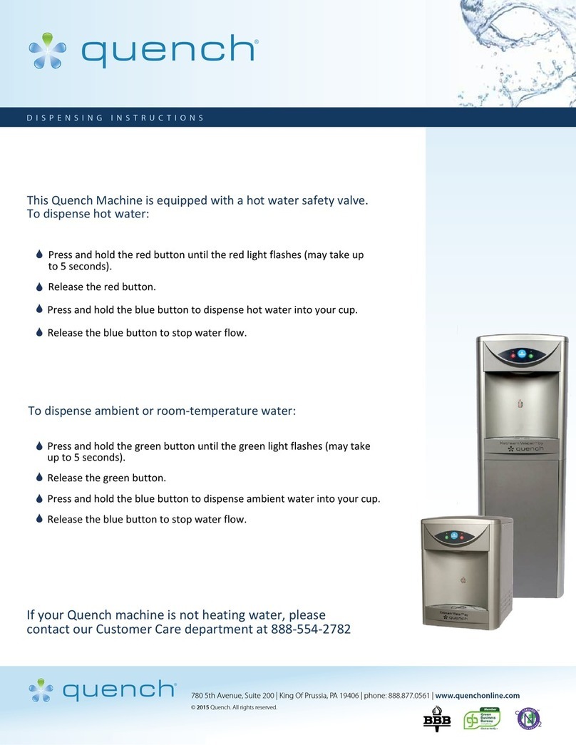
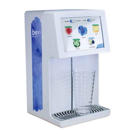
Quench WB-BW-AQ User manual

INSTANT BOILING
WATER DISPENSER
Installation Guide &
Owner’s Manual
WB-BW-AQ

2 3
1. IMPORTANT NOTES
2. WATER QUALITY
3. INSTALLATION
3.1. LOCATION
3.2. OPENING THE UNIT
3.3. MINIMUM CLEARANCE
3.4. MOUNTING
3.5. WATER SUPPLY CONNECTION
3.6. VENT/OVERFLOW CONNECTION
3.7. DRAIN CONNECTION
3.8. TAP OUTLET
3.9. ELECTRICAL REQUIREMENTS
4. OPERATION
4.1. MODE 1 OPERATION
4.2. MODE 2 OPERATION
4.3. MODE 3 OPEARTION
4.4. DIMENSION SPECIFICATION TABLE
4.5. DIMENSION SPECIFICATION FOR 2.5L, 5L, 7.5, 10L, 15L, 25L
4.6. SPECIFICATIONS
5. TEMPERATURE ADJUSTMENT
6. FAULT FINDING GUIDE
7. SPARE PARTS LIST
8. NOTES
3
3
3
3
4
4
4
4
4
5
5
5
5
5
6
6
6
7
8
9
9
10
11
PAGECONTENT This appliance can be used by chil-
dren aged from 8 years and above
and people with reduced physical,
sensory or mental capabilies or
lack of experience and knowledge
if they have been given supervision
or instrucon concerning use of the
appliance in a safe way and
understand the hazards involved.
Children must not play with the ap-
pliance. Cleaning and user mainte-
nance must not be done by children
without supervision.
• If the supply cord is damaged,
it must be replaced by the
manufacturer, its service agent
or similarly qualied person in
order to avoid hazard.
• The new hose sets supplied with
the appliance are to be used
and old hose-sets should not be
reused.
• This appliance is for indoor use
only.
• The appliance has to be installed
in a horizontal posion.
1. IMPORTANT NOTES
1.1 The Boiling Water Unit is designed and
manufactured to operate at a maximum in-
coming mains cold water pressure of 3 BAR.
Should the water pressure exceed 3 BAR, an
inline pressure reducing valve must be ed.
The min. environment temperature is 5°C
and the environment temperature is not
more than 45°C.
Prohibion of outdoor use.
1.2 Please ensure that the mains cold water
supply is connected to the indicated water
inlet connecon of the Boiling Water Unit.
(at the base of the solenoid valve) and that
the unit vent connecon always has a free
ow of air into and out of the boiling water
chamber.
1.3 The Boiling Water Unit is a simple tech-
nologically advanced electronic automac
boiling water system and operates dierent-
ly and more eciently to other mechanical
systems.
Please familiarise yourself with the lling and
operang modes of this electronic system as
explained on Page 5 and 6 of the Manual.
1.4 The Boiling Water Unit system facilitates
a boiling water temperature adjustment for
dierent altude installaons. A temper-
ature trim pot is located in the electronic
controller (PCB). Should a temperature
adjustment be necessary, the procedure is
detailed on page 9 of the manual.
1.5 The Boiling Water Unit produces boiling
water and care should be taken at all mes
when using it.
2. WATER QUALITY
Cauon is suggested if the Boiling Water Unit
is to be connected to a water supply with a
high content of silica of calcium. Water sup-
plies of this nature may be detrimental to the
unit’s operaon and may cause the warranty
to become void. Fo. further informaon
relang to the guidelines of water quality,
contact your local service agent for advice.
3. INSTALLATION
This Boiling Water Unit shall be installed by
a qualied service person. The installaon
must comply with the local building regula-
ons and the relevant wiring and plumbing
regulaons.
Please read this booklet as it contains important informaon about the correct
installaon and operaon of the Boiling Water Unit. Failure to install the Boiling Water
Unit correctly will deem the product warranty void.

4 5
3.1 LOCATION
This unit is designed for interior installa on
only and is NOT WEATHERPROOF. If the unit
is to be installed outside, it must be protect-
ed from the weather and from freezing.
3.2 OPENING THE UNIT
To remove the jacket from all models, re-
move the retaining screws on the sides and
pull the jacket forward.
3.3 MINIMUM CLEARANCES
All units require a minimum clearance of
50 mm on all sides, however, we recommend
you leave sucient clearance for servicing.
3.4 MOUNTING
The Boiling Water unit, when installed is sus-
pended from mounng screws located into
keyhole slots at the back of the unit (refer
to the dimension specicaon diagrams on
page 6 or the template on the carton). Be
sure that the mounng screws are securely
inserted into the keyhole slots. The screws
MUST be anchored in such a way, that they
will hold the weight of the unit when lled
with water (refer to the weight table on P. 8).
3.5 WATER SUPPLY CONNECTION
Mains cold water supply (refer to pressure
table on Page 8 for operang water
pressures) must be piped and connected to
the 1/2” BSP inlet ng located on the le
hand side underneath the unit. An accessible
isolang valve must be installed near the
unit.
This unit contains a strainer on the water
inlet connecon. To ensure connuing
sasfactory operaon, it is suggested that
the inlet strainer be serviced every six
months. Where poor water quality is present
it is recommended to install an addional
auxiliary lter.
For rear entry connecon, we recommend
that you use a braided exible hose with a
90° elbow for ease of connecon.
3.6 VENT/OVERFLOW CONNECTION
Connect a 15 mm (1/2”) pipe to the vent/
overow connecon (1/2” BSP). This pipe
must have a connuous fall, not exceeding
3 metres in length, or contain no more than
4 bends.
During the normal operaon of the Boiling
Water unit the vent/overow connecon
may discharge small quanes of steam
and condensate, so it is ESSENTIAL that the
drain pipe is aached to the vent/overow
connecon. This drain pipe must discharge
to waste at a point where no scald injury or
inconvenience is caused.
Ensure that the venUoverow line remains
open because the Boiling Water unit tank is
not designed to be pressurised. It is recom-
mended to install an air break in the vent/
overow drain line no more than 300 mm
from the Boiling Water unit.
3.7 DRAIN CONNECTION
There is a drain screw located on the under-
side of the unit to completely drain the tank
for servicing.
Before removing the drain screw, ensure
the appliance has been switched o and the
water is not hot enough to scald.
CAUTION
This unit is not suitable for installaon
in an area where a water jet could be used.
This unit must not be cleaned using
a water jet.
3.8 TAP OUTLET
To prevent damage during transportaon,
the tap is bubble-wrapped and placed inside
the carton.
The tap is ed to the threaded tap outlet
extension with an “o” ring seal ed and
xing screw to secure in the vercal posion.
PLEASE NOTE:
Installaon and maintenance of the Boiling
Water Unit should be carried out by
a qualied service person.
3.9 ELECTRICAL REQUIREMENTS
All models
230 Volts AC, 50HZ,
Single Phase
ELEMENT RATING
1800 Was - 2.5L
2000 Was - 5L to 10L
2400 Was - 15L
3000 Was - 25L
A exible cord complete with a plug is sup-
plied on all models. Do not loosen the cord
grip or pull excess cord into the Unit. If the
supply cord of this unit is damaged, it must
be replaced by a qualied service person.
CAUTION
THIS APPLIANCE MUST BE EARTHED
4. OPERATION
When the installaon is complete, rst turn
on the water supply and then switch on the
power, which will engage the solenoid valve
and the unit will automacally begin to ll
and the heang sequence will commence.
The water is heated in small quanes,
so boiling water is available at all mes.
The electronic control unit constantly
controls the water level and the water
temperature.
4.1 MODE 1 OPERATION
To follow through the sequence of events in
order, it is necessary that we consider the
unit is switched on for the rst me.
When the unit is switched on, the controller
scans the Level Probe condion, and having
established that, then executes a sequence
of events parcular to that mode.
1. The Controller scans the Level Probe to
establish the Level Probe condion. Both
Probes (low and high) will be found to be in
an OPEN condion i.e. no water pressent.
This then places the unit in MODE 1 condi-
on.
2. The Solenoid valve is then energised,
allowing water to enter the tank.
3. Water connues to enter the tank unl
such me as the Low Level Probe becomes
“CLOSED”, i.e. water present, up to the end
of the Low Level Probe.
4. The Solenoid Valve is then powered, stop-
ping the ow of water into the tank.
5. The Controller then steps into MODE 2
new line condion.

6 7
4.2 MODE 2 OPERATION
1. The element is energised, allowing heang
of the water to take place.
2. The connued heang results in the water
reaching the set point, detected by the
Thermistor.
3. The Solenoid Valve is then energised,
allowing ambient water to enter the tank
thus reducing the water temperature by a
maximum of 2°C and results in a shi away
from the set point, again detected by the
thermistor.
4. When this occurs, the solenoid valve is
then de-energised, stopping the ow of
water into the tank.
5. Steps 2 to 4 are repeated unl the High
Level Probe becomes “CLOSED”, i.e. water is
present.
4.3 MODE 3 OPERATION
1. The Element remains energised, allowing
heang of water to take place, resulng in
the water aaining set point, detected by
the Thermistor.
2. The Element is then de-energised allowing
cooling of water to take place.
3. Cooling connues to take place through
heat loss via the tank insulaon unl set
temperature point minus 2°C is reached,
detected by the Thermistor.
4. The Element is then energised, allowing
heang of water to take place.
5. Steps 1 to 4 are repeated unl the water
is drawn from the unit, at which me the
controller then steps back into MODE 2.
4.4
4.5. DIAGRAM: DIMENSION SPECIFICATION 2.5L, 5L, 7.5L, 10L, 15L MODELS
DIMENSION
SPECIFICATION
TABLE
– referring to diagram
on the next page
WB-BW-AQ2.5L/5L/7.5L/IOL/15L
WB-BW-AQ25L
E
E

8 9
(BAR)
(BAR) 0.7
3 33 3 33
0.7 0.70.7 0.7 0.7
4.6. SPECIFICATIONS
5. TEMPERATURE ADJUSTMENT
A trim pot is located at the right rear of the
control box. Access is provided by means
of a 10 mm diameter hole. All Electronic
controllers are factory set to deliver water at
a temperature of approximately 97°C.
To change water temperature to 92°C:
rotate the trim potscrew an-clockwise.
IMPORTANT
Temperature adjustment should be carried
out by a qualied service person.
97°C
RED
92°C
BLUE
6. BOILING WATER UNIT FAULT FINDING GUIDE
SYMPTOM POSSIBLE CAUSE SOLUTION
1. The unit does not ll
with water
There is no power supply.
There is no water supply.
The lter is blocked.
Electronic Controller failure.
Solenoid Valve failure.
Check the electrical supply.
Check the water supply .
Check the lter, clean or replace.
Test the Electronic Controller.
Check resistance of the solenoid,
replace if broken.
2. The unit lls water
to low level and does
not heat
Thermal cut-out tripped.
Heang Element failure.
Electronic Controller failure.
Thermistor failure.
Reset the Thermal cut-out.
If the Heang Element is properly wired,
then check its resistance.
Test the Electronic Controller.
Replace Thermistor.
3. The unit boils
connuously
Temperature is not correctly set.
Electronic Controller failure.
Thermistor failure.
Set the Temperature Adjustment Trim Pot.
Test the Electronic Controller.
Replace Thermistor.
4. The unit overows
Incoming water pressure is too high.
Solenoid valve failure.
Level probe failure.
Reduce incoming water pressure.
Disassemble the solenoid valve and blow
air through it. If air ows through, replace
the solenoid valve.
Clean the level probe.
Replace the level probe.
5. There is no water from
the tap.
The unit did not ll with enough water.
The tap diaphragm is disconnected from
its spindle.
See 1.& 2. Above.
Drain water out of the unit.
When the unit is empty, disassemble and
repair the tap via cleaning or replacement.
6. No electrical power
to unit. Power Supply failure. Will restart automacally when electrical
power is restored.
7. No water to unit Mains water supply failure.
When water supply restored;
1. Connue to use as normal and the relling
process will automacally restart.
2. Switch o electrical supply for 30
seconds & switch on again.

10 11
7. SPARE PARTS LIST 8. NOTES

Other Quench Water Dispenser manuals
Popular Water Dispenser manuals by other brands

Aroma
Aroma Hot Water Central AAP-325F instruction manual

Kenmore
Kenmore microMAX 625.348460 owner's manual

DS Services of America
DS Services of America Pure water dispenser 200k Series owner's manual

nijadistil
nijadistil NJ-DH01 instruction manual

Elkay
Elkay Space-ette FD7008 2HJO Series Installation, care & use manual

Ispring
Ispring WCB Series user manual