Franklin Water Treatment PTS1 Series Quick start guide

Franklin Water Treatment, LLC
12630 US Highway 33 N
Churubusco, IN 46723
Phone (260) 693-1972 Fax (260) 693-0602
PTS1Instruction Manual 230511.docx
PTS1 Series
Water Softener System
Installation Instructions and Owner’s Manual

1
Pre-installation Instructions
Page 2
General Installation
Page 3
Bypass Valve
Page 4
Installation Instructions
Page 5
Control Valve Programming –Set Time-of-Day
Page 7
Control Valve Programming –Initial Settings
Page 8
Control Valve Displays & Button Operation
Page 11
Troubleshooting Guide
Page 12 - 14
Specifications
Pages 15-16
Component Parts Breakdown & List
Page 17
Control Valve Breakdown
Page 18
Control Valve Parts List
Page 19
Installation Fitting Assemblies
Pages 21-23
Limited Warranties
Page 24-25
TABLE OF CONTENTS

2
Description of the softener
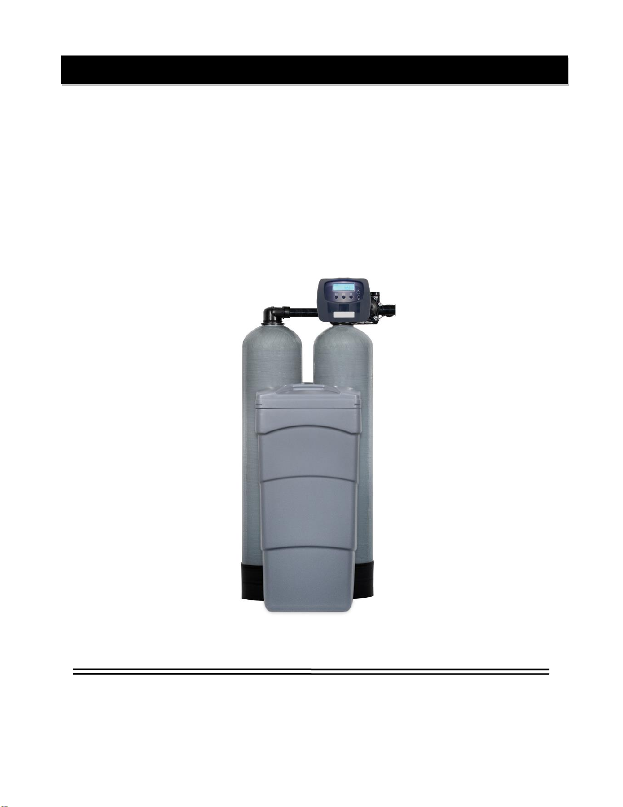
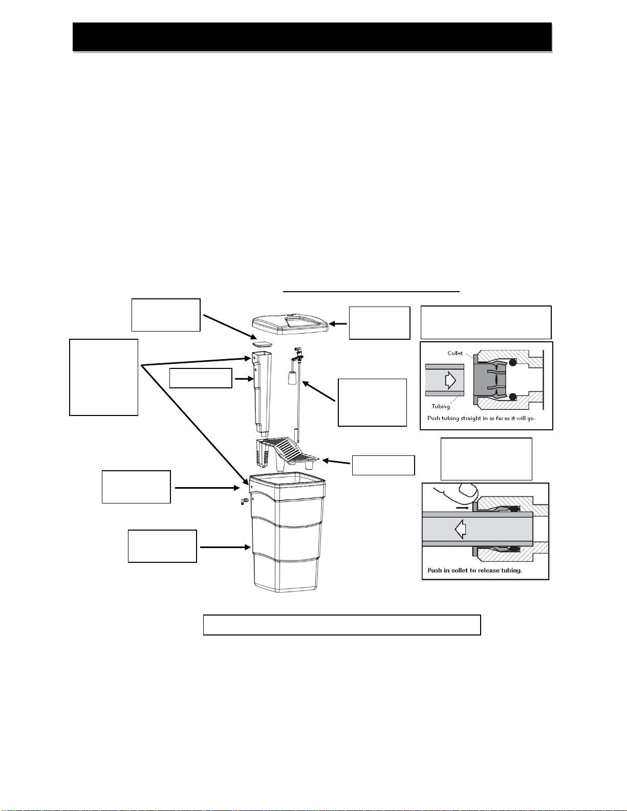
The softener system includes two mineral tanks (with gravel, distributor and softener resin), one brine tank (with
salt shelf {some models}, brine well, brine tank lid and safety brine valve), and a twin alternating, meter initiated,
digital, backwashing control valve with bypass and brine line.
Successful Application
Softeners are designed to remove hardness minerals (calcium and magnesium) from water by the process of
ion exchange. They may also remove small amounts of “clear water” iron (2 ppm or less). Softeners are not
designed to remove “red water” iron or bacterial iron. If greater levels of iron, “red water” or iron bacteria are
present, an iron filter must precede the softener. Softeners are not designed to remove particulates. If there is
any sediment or turbidity present in the water, a backwashing filter with appropriate media must precede the
softener. Only specialty tannin softeners are designed to remove tannins and the yellow to tea color from water.
Softeners will not reduce hydrogen sulfide (“rotten egg” odor).
Time of Regeneration
Periodically the control valve will go through regeneration. Regeneration is factory preset to 2:00 A.M. The time
of regeneration may be changed if needed (see programming procedures on page 7).
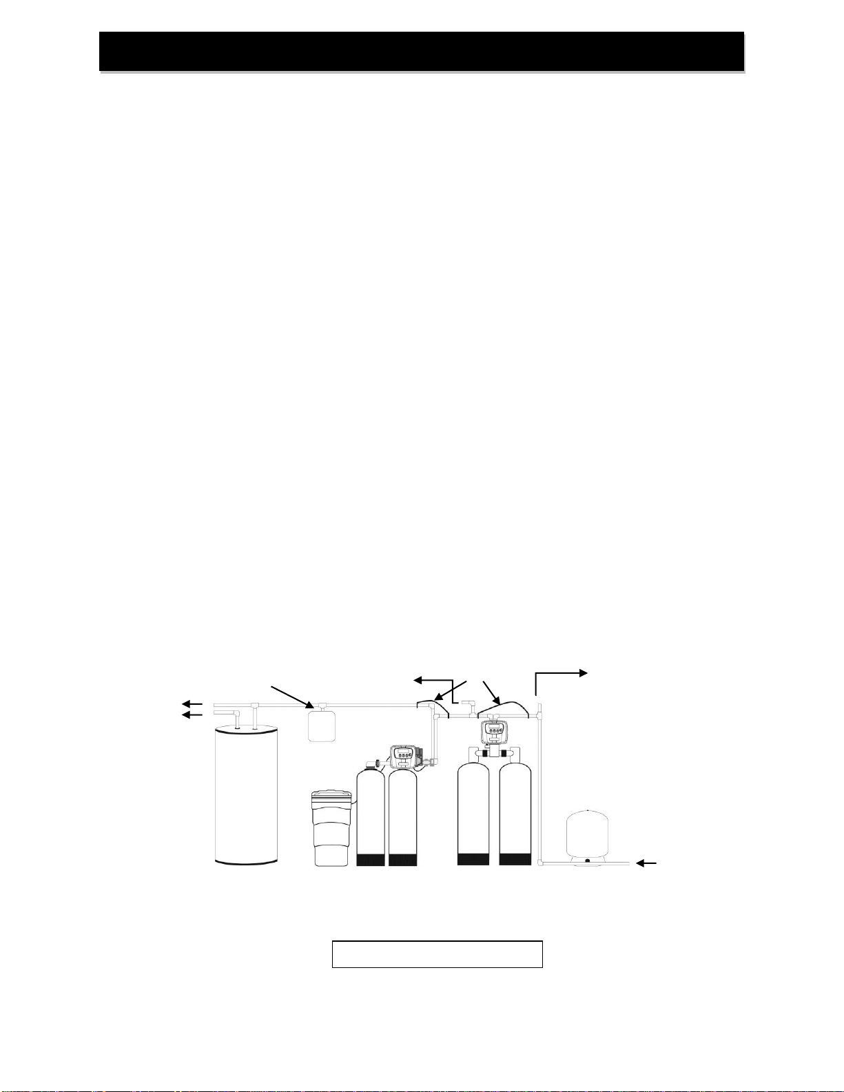
Location Considerations
The proper location to install the softener will ensure optimum performance and satisfactory water quality. The
following factors should be considered in selecting the location of this system.
1. The softener must be installed after the pressure tank (private well system only). Operating
pressure of the softener must be limited to within 25 –100 psi range.
2. The softener should be installed after any iron filter and/or other backwashing filter.
3. If chlorine is present in the supply water a whole house carbon filter (CS-1 or other backwashing
carbon filters or DF non-backwashing carbon filters.) should be installed before the softener.
4. The system must not be subject to freezing temperatures
5. Ensure that any in-line filter installed prior to the softener does not restrict the flow or pressure
required to backwash the softener.
6. The system should be installed as close as possible (preferably within 15’) to an adequate floor or
laundry drain capable of handling the backwash cycle volume and flow rate (refer to unit
specifications on pages 15-16). An air gap should be provided between the drain line and
plumbing drain.
7. All water conditioning equipment should be installed at least 10’ prior to the water heater. Water
temperatures exceeding 100°F can damage the internal components of the control valve and
mineral tank. An expansion tank may need to be installed in the line to the water heater to allow for
thermal expansion and comply with local plumbing codes.
8. Appliances requiring extended periods of continuous or high flow water use (i.e., geothermal heat
pumps, swimming pools, lawn irrigation, outside hose bibs, etc.) should bypass all water
conditioning equipment unless the equipment has been specifically designed for that purpose.
Pre-Installation Instructions

3
GENERAL INSTALLATION & SERVICE WARNINGS
The softener is not designed to support the weight of plumbing.
Do not use Vaseline, oils, other hydrocarbon lubricants or spray silicone anywhere. A silicone lubricant may be
used onblack "O" Rings but is not necessary. Avoid any type of lubricants, including silicone, on red or clear lip
seals.
Do not use pipe dope or other sealants on threads. Teflon® tape must be used on the threads of the 1" NPT
inlet and outlet and on the threads for the drain line connection. Teflon® tape is not used on the nut connections
or caps because "O" Ring seals are used.
The nuts and caps are designed to be unscrewed or tightened by hand or with the special plastic Service
Wrench, (CV3193, not included). If necessary, pliers can be used to unscrew the nut or cap. Do not use a pipe
wrench to tighten nuts or caps. Do not place screwdriver in slots on caps and/or tap with a hammer.
NOTE: If the plumbing system is used as the ground leg of the electric supply, continuity should be maintained
by installing ground straps around any non-conductive plastic piping or bypass used in the installation.
Make sure the softener is not installed backwards. The softener will not function properly if installed backwards
and softener resin may be forced into the water lines. Arrows molded into the valve body indicate the direction
of flow.
Site Requirements
● water pressure -- 25-100 psi (1.7 –6.9 bar)
● water temperature -- 33-100°F (0.5-37.7°C)
● electrical -- 115/120 V, 60 Hz uninterrupted outlet dry locations only
● the tank should be on a firm level surface
Typical Installation
Water Heater
UntreatedWater
UntreatedWater for
geothermal heat pumps,
swimming pools, lawn
irrigation, hosebibs etc.
FIGURE 1: Typical Installation
General Installation
Filtered Hard Water
Iron Filter w/ inlet check
valve or Backwash Filter
(if needed)
Softener
Brine Tank
PressureTank
(well system only)
Tank
Treated Water
GroundingStrap
Expansion Tank

4
The bypass valve is used to isolate the control valve from the plumbing system's water pressure in order to
perform controlvalverepairs or maintenance.The 1" full flow bypass valve incorporates four positions including
a diagnostic position that allows a service technician to have pressure to test a system while providing untreated
bypass water to the building. Be sure to install bypass valve onto main control valve, before beginning plumbing
or make provisions in the plumbing system for a bypass. The bypass body and rotors are glass filled Noryl®
and the nuts and caps are glass filled polypropylene. All seals are self-lubricating EPDM to help prevent valve
seizing after long periods of non-use. Internal "O" Rings can easily be replaced if service is required. The
bypass consists of two interchangeable plug valves that are operated independently by red arrow shaped
handles. The handles identify the direction of flow. The plug valves enable the bypass valve to operate in four
positions.
1. Normal Operation Position: The inlet and outlet handles point in the direction of flow
indicated by the engraved arrows on the controlvalve. Water flows through the control
valve for normal operation of a water softener or filter. During the regeneration cycle this
position provides regeneration water to the unit, while also providing treated water to
the distribution system (Fig. 2).
2. Bypass Position: The inlet and outlet handles point to the center of the bypass. The
system is isolated from the water pressure in the plumbing system. Untreated water is
supplied to the building (Fig. 3).
3. Diagnostic Position: The inlet handle points toward the control valve and the outlet
handle points to the center of bypass valve. Untreated supply water is allowed to flow to
the system and to the building, while not allowing water to exit from the system to the
building (Fig. 4). This allows the service technician to draw brine and perform other tests
without the test water going to the building.
NOTE: The system must be run through a rinse cycle before returning the bypass valve
to the normal position.
4. Shut Off Position: The inlet handle points to the center of the bypass valve and the outlet
handle points away from the control valve. The water is shut off to the building. The water
treatment system will depressurize upon opening a tap in the building. A negative pressure
in the building combined with the softener being in regeneration could cause a siphoning
of brine into the building. If water is available on the outlet side of the softener it is an
indication of water bypassing the system (Fig. 5)
Figure 2 - Service
Figure 3 - Bypass
Figure 4 - Diagnostic
Figure 5 –Shut Off
Bypass Valve

5
STEP 1: Unpack softener, making sure to remove entire contents of the shipping container prior to
disposal.
STEP 2: Fill the resin tanks. (3 cubic foot & larger units). Cover the top of the distributor tube of
each resin tank with the included red cap and, using the included blue media funnel, pour the
included softener resin into the resin tanks.
STEP 3: Install the control valve & 2nd tank in/out head (3 cubic foot & larger units). Clean resin
tanks threads to remove any resin beads. Remove red cap from distributor tube and install
control valve and 2nd tank in/out head by threading them securely onto the mineral tanks.
(O-ring seal; HAND TIGHTEN ONLY!).
STEP 4: Shut off all water at main supply. On private well system, turn off power to pump and drain
pressure tank. Make certain pressure is relieved from complete system by opening nearest
faucet to drain system. SHUT OFF FUEL / ELECTRICAL SUPPLY TO WATER HEATER.
STEP 5: Plumb the water supply line to the unit's bypass valve inlet located on the right side, front,
as you face the unit. There are a variety of installation fittings available. They are listed under
Installation Fitting Assemblies, pages 21-23. When assembling the installation fitting package
(inlet and outlet), connect the fitting to the plumbing system first and then attach the nut, split
ring, and "O" Ring. Heat from soldering or solvent cements may damage the nut, split ring, or
"O" Ring. Solder joints should be cool and solvent cements should be set before installing the
nut, split ring, and "O" Ring. Avoid getting solder flux, primer, and solvent cement on any part
of the "O" Rings, split rings, bypass valve, or control valve. If the building's electrical system is
grounded to the plumbing, install a copper grounding strap from the inlet to the outlet pipe.
Plumbing must be done in accordance with all applicable local codes. MAKE CERTAIN
WATER ENTERS THROUGH INLET AND DISCHARGES THROUGH OUTLET
Installation Instructions
FIGURE 6: Top View of Control Valvewith Bypass Installed
Inlet from Water Supply
Outlet to Service
DLFC Retainer Clip
BLFC Retainer Clip
Drain Line Flow Control
Assembly
(Drain fitting Not Shown)
Brine Refill Elbow and
Brine Line Flow Control
Assembly
Inlet / Outlet Head
Bypass
Meter Module
2nd Tank
Connection Port
Transfer Drive

6
STEP 6: Apply thread tape to DLFC Assembly. Remove drain line flow control (DLFC) retainer clip
(Figure 6, Page 5) and remove the DLFC assembly from the valve body, (Figure 6, Page 5). Apply
thread tape to threads. Slide drain fitting compression nut onto provided drain tubing and place the
tube insertinside the end of the tubing. Insert tubing end with insert into drain elbow and tighten the
compression nut onto the thread taped elbow. Reinsert DLFC assembly into the valve body,
makingcertain itis FULLY inserted before replacing the retaining clip.
STEP 7: Install softener drain line. Use ½” I.D. polyethylene tubing (DO NOT USE FLEXIBLE VINYL
TUBING!) to run drain line from control valve DLFC fitting (Page 19, Reference 19) to floor drain or
sump pit capable of handling the backwash rate of the filter (refer to specifications and flow rate on
pages 15-16) or discard the compression fitting and use 3/4" NPT fitting to connect a rigid pipe drain
line (recommended). If backwash flow rate is greater than 7 gpm, use ¾” NPT connector with rigid
drain line. There must be an air gap at the end of the drain line to prevent siphoning of wastewater.
Length of drain line should be 15’ or less. AVOID OVERHEAD DRAINS.
STEP 8: Connect brine line between the softener and safety brine valve. Install the 3/8" O.D.
polyethylene tube from the brine refill elbow (Figure 6, Page 5) to the safety brine valve (Figure 7)
inside the brine tank. DO NOTINSERT THE BRINE REFILL LINE INTO THE BRINE TANK
OVERFLOW ELBOW FITTING. Do not put salt in the tank until STEP 27.
STEP 9: Install brine tank overflow drain line (not included). An overflow drain lineis recommended
where a brine overflowcould damage furnishings or the building structure. Your softener is
equipped with a brine tank safety float (Figure 7)which greatly reduces the chance of anaccidental
brine overflow. In the event ofa malfunction, however, an overflow line connection will direct the
"overflow" to the drain instead of spilling on the floorwhere itcouldcause considerable damage.
This fitting is an elbow on the side of the brine tank (Figure 7). Attach a length of1/2"I.D. (5/8”
O.D.) tubing to fitting and run to drain.
(Continued on next page)
Installation Instructions (cont.)
FIGURE 3: Brine Tank Components
Insert brine tube into quick
connect fitting
Remove brine tube
from quick connect
fitting
Insert brine
tubing here
through
hole in brine
tank shell
Safety
Brine Valve
Assembly
Brine
Tank Lid
Brine Well
Lid
Brine Well
Salt Grid
Overflow
Elbow
Brine Tank
Shell

7
Do not elevate overflow line higher than 3" below bottom of overflow fitting. DO NOT “TIE”
THIS TUBE INTO THE DRAIN LINE OF THE CONTROL VALVE AS IT WILL RESULT IN
OVERFILLING THE BRINE TANK AND FLOODING. The overflow line must be a direct,
separate line from the brine tank overflow elbow to a drain or sump pit.
STEP 10:With the bypass valve handles in the bypass position (Figure 3, Page 4), turn on water
supply. Turn the inlet bypass valve handle to the diagnostic position (Figure 4, Page 4) and
allow the online tank to pressurize. NOTE: the INLET and OUTLET knobs turn clockwise to
close the port to the softener and counterclockwise to open the port to the softener. Check for
leaks andcorrect as needed. Return the bypass valve handles to the bypass position.
STEP 11: Program control valve. Plug the transformer of the control valve into an uninterrupted
electrical outlet (not wired to a switch) and use the buttons on the front of the control valve to
adjust the initial settings:
A) SET THE TIME OF DAY
1. Press the “CLOCK” button
a. The upper left of the display will show “TIME HOUR”
b. The lower left of the display will show “SET”
c. The hour and AM or PM will flash
2. Press the UPor DOWN buttons (triangle pointing up or down) until the correct
combination of hour and “AM” or “PM” is reached to match the current time.
3. Press the “NEXT” button
a. The upper left of the display will show “TIME MINUTES”
b. The lower left of the display will show “SET”
c. The minutes will flash
4. Press the UPor DOWN buttons until the minutes match the current time. If you
need to go back to the HOUR screen press the “REGEN” button.
5. Press the “NEXT” button to return to the main screen.
Power Loss - Lithium battery on circuit board provides up to 2 years of
time clock backup during power outages. If the power is out when battery
is depleted, only time of day needs to be reset, all other values are stored
in non-volatile memory. When time of day is flashing, replace lithium coin
type 2032 battery. Battery back-up feature will be activated after 24 hours
of power.
B) Enter Programming: The manufacturer has preset the unit so gallons between
regenerations are automatically calculated after hardness is entered.
1. Hardness: Press “NEXT” and UP (triangle pointing up) buttons simultaneously
for 3 seconds.
a. The upper left of the display will show “WATER HARDNESS”
b. The lower left of the display will show “SET”
c. A number will flash (default 20) followed by “GR” (grains).
2. Based on water analysis results (obtained either from a lab or in-field testing). Set
the amount of hardness in grains per gallon using the UP or DOWN (triangle
pointing up or down) buttons. The allowable range is from 1 to 150 in 1 grain
Installation Instructions (cont.)

8
increments. Note: Increase the grains per gallon if soluble (“clear water”)
iron and/or manganese is present (1 ppm iron = 3 gpg hardness and 1 ppm
manganese = 5 gpg hardness).
3. Regeneration Days Override: Press the “NEXT” button
a. The upper left of the display will show “DAYS BETWEEN REGEN”
b. The lower left of the display will show “SET”
c. A number will flash (default 14)
4. Using the UP or DOWN (triangle pointing up or down) buttons, set the maximum
number of days (default 14, recommended) the softener will go without initiating
regeneration even if the unit still has capacity remaining based on water usage,
hardness setting and capacity setting. The allowable range is 1 to 28 and OFF. If
set to OFF, the unit will only regenerate based on water usage, hardness and
capacity.
5. Regeneration Time: Press the “NEXT” button
a. The upper left of the display will show “REGEN TIME HOUR”
b. The lower left of the display will show “SET”
c. The hour and AM or PM will flash
6. Regeneration Hour: Using the UP or DOWN buttons, set the combination of
hour of day and “AM” or “PM” that the BACKWASH cycle of regeneration should
occur. Please note that regeneration will actually begin with the short (less than
10 minutes) Brine Fillcycle 90 minutes prior to the time set here followed by 90
minutes (default) of inactivity to allow water in the brine tank to become saturated
with salt.
7. Press the “NEXT” button
a. The upper left of the display will show “REGEN TIME MINUTES”
b. The lower left of the display will show “SET”
c. The minutes will flash
8. Regeneration Minutes: Using the UP or DOWN buttons, set the minutes portion
of the time when regeneration should occur. If you need to go back to the HOUR
screen press the “REGEN” Button.
9. Energy Saver: Using the UP or DOWN buttons, set the mode of operation for
Energy Saver; OFF, ON or AUTO. Unless set to OFF the display will dim when
not actively using the buttons.
10. Exit Programming: Press the “NEXT” button
a. The upper left of the display will show “TIME”
b. The current time of day will be shown on the right side of the display
c. Only the colon between the hour and minutes will be flashing

9
STEP 12: Initiate Manual Regeneration (Fill Cycle): NOTE –With the bypass handles in the
“BYPASS” position, press and hold the “REGEN” button until the motor starts. The word
“Fill” will appear in the upper left of the display and a count-down timer will appear in the lower
right of the display. Take this opportunity to add water to the brine tank, with a hose or
bucket, up to the top shelf of the salt grid (if applicable) or above the air check. When
the count-down clock reaches 00:00 or when the “REGEN” button is pressed the control valve
will advance to the next cycle.
STEP 13: Softening Cycle: “SOFTENING” will appear in the upper left of the display. Another count-
down timer will appear in the lower right of the display. Both times through this cycle: Turn
the inlet bypass valve handle to the diagnostic position (Figure 4, Page 4) and allow the online
tank to pressurize. Check for leaks and correct as needed. Return the inlet bypass valve
handle to the bypass position (Figure 3, Page 4). Both times through this cycle: Press
the “REGEN” button to advance the control valve to the “BACKWASH” cycle.
STEP 14: Backwash Cycle: There may be an audible release of pressure to the drain. Another count-
down timer will appear in the time-of-day position, “BACKWASH” will be shown in the upper
left of the display.
STEP 15: Both times through this cycle: Slowly turn the INLET knob of the bypass valve counter-
clockwise to the diagnostic position (Figure 4, Page 4) to release any remaining air from the
offline mineral tank. 2nd time ONLY through this step proceed to STEP 22.
STEP 16: When water flows clear to the drain then turn the INLET knob of the bypass valve clockwise
until it is fully in “Bypass” position (Figure 3, Page 4). Press the “REGEN” button to advance to
the “Brine Draw” cycle.
STEP 17: Brine Cycle: “REGENERANT DRAW DN” will appear across the top of the display, A new
count-down timer will begin. Press “REGEN” to advance to the second “Backwash” cycle.
STEP 18: Backwash Cycle 2: A “1:00” minute count-down timer will appear in the lower right of the
display and “BACKWASH” will be shown in the upper left, with a flashing “2” below. Press
“REGEN” to advance to the “Rinse” cycle.
STEP 19: Rinse Cycle: Another count-down timer will appear in the time-of-day position and “RINSE”
will be shown in the upper left of the display. Press the “REGEN” button to exit manual
regeneration.
STEP 20:Exit Manual Regeneration: “SOFTENING” will flash in the upper left of the display and the
drive motor will run for a few seconds and then the display will return to its normal position
when in service.
STEP 21: Purge air from second tank: Repeat steps 12 –15 and then proceed with step 22.
STEP 22: When the water flowing to drain runs clear, press the “REGEN” button to advance to the “Brine
Draw” cycle.
Installation Instructions (cont.)

10
STEP 23: Brine Cycle: “REGENERANT DRAW DN” will appear across the top of the display and a new
count-down timer will begin. Allow this cycle to continue until most of the water is drawn
out of the tank. Press “REGEN” to advance to the second “Backwash” cycle.
IMPORTANT: If most of the water is NOT drawn out of the brine tank within 10 –20
minutes (depending on softener size); complete the next two steps of installation and
refer to the “Brine Tank Overfill” section of Troubleshooting (page 12) to resolve this
problem. Failure to do so will prevent the softener from functioning properly. Test the
solution by returning to STEP 12 and proceeding from there.
STEP 24: Backwash Cycle 2: A “1:00” minute count-down timer will appear in the lower right,
“BACKWASH” will be shown in the upper left of the display with a flashing “2” below. Press
“REGEN” to advance to the “Rinse” cycle.
STEP 25: Rinse Cycle: Another count-down timer will appear in the time-of-day position and “RINSE”
will be shown in the upper left of the display. Press “REGEN” to exist manual regeneration.
STEP 26: Exit Manual Regeneration: “SOFTENING” will flash in the upper left of the display and the
drive motor will run for a few seconds and then the display will return to its normal position
when in service.
STEP 27: Add salt to brine tank. Fill the brine tank with salt. Any type of softening salt may be used.
STEP 28: TURN ON FUEL / ELECTRICAL SUPPLY TO WATER HEATER.
Installation Instructions (cont.)

11
USER DISPLAYS
When the system is operating, one of several displays may be shown. Pressing NEXT will alternate between
the displays. One of the displays is the current time of day. The second display shows days to a regen/gallons
remaining. Days To A Regen is the number of days left before the system goes through a regeneration cycle.
Capacity remaining is the number of gallons that will be treated before the system goes through a regeneration
cycle. The third display is current flow in gal/min. The user can scroll between the displays as desired by
pushing NEXT or display will scroll automatically. When water is being treated (i.e. water is flowing through the
system) the word "GPM" flashes on left side of display when other than flow rate is displayed. User screens will
continuously scroll, switching views every 3 seconds. If the screens are manually scrolled, this screen will
remain constant for 5 minutes then continue to scroll. The conditional screens will take precedence over the
scrolling and the conditional conditions will apply. To manually reduce capacity, press down button while
capacity remaining or days to a regen is displayed.
MANUAL REGENERATION
Sometimes there is a need to regenerate the system sooner than when the system calls for it, usually referred
to as manual regeneration. There may be a period of heavy water usage because of guests or a heavy laundry
day. To initiate a manual regeneration at the preset delayed regeneration time, press and release “REGEN”.
The words “REGEN TODAY” will flash in left corner of display as it scrolls through displays to indicate that the
system will regenerate at the preset delayed regeneration time. If you pressed the “REGEN” button in error,
pressing the button again will cancel the request. To initiate a manual regeneration immediately, press and hold
the “REGEN” button for five seconds. The system will begin to regenerate immediately. The request cannot be
cancelled. You must cycle all the way through the cycles to make it stop. PLEASE NOTE: This will reset the
meter. Note: If the salt tank does not contain salt, fill with salt and wait at least two hours before regenerating. If
two regenerations are desired within 24 hour period, press /release REGEN button. REGEN TODAY will flash
on screen. Press and hold REGEN button until valve initiates an immediate regeneration.
Displays & Button Operation

12
PROBLEM
CAUSES
SOLUTIONS
Brine tank overfills or
does not draw brine
A) Loose connector at
either end of the
brine line
B) Plugged injector
C) Brine line inserted
into the brine tank
overflow fitting
rather than
connected to the
safety brine valve
D) Softener drain line
connected to brine
overflow fitting or
overflow drain line
E) Obstruction in the
control valve
F) Problems with drain
line: plugged,
frozen, kinked,
flexible tubing,
overhead
installation,
diameter too small,
longer than 15’
G) Missing BLFC
H) Missing brine stem
I) Drive cap too loose
1) Push tubing completely into the connector
at either end of brine line
2) Clean injector and injector screen
3) Verify brine line is installed correctly
4) Verify softener drain line is not connected
to brine overflow elbow or brine overflow
drain line
5) Check for debris in DLFC Assembly, BLFC
Assembly, injector, injector screen
6) Manually put softener into Backwash Cycle
(page 8, beginning with step 12) and
unplug the transformer for 30 minutes to
dislodge debris from inside the control
valve or disassemble and clean control
valve internal components
7) Resolve issues with the drain line
8) Verify brine line flow control button is not
missing
9) Verify piston brine stem is not missing
10) Tighten drive cap
Hard water or
softener not using salt
A) Electrical outlet is
dead or on a switch
B) No salt in the brine
tank
C) Salt in the brine tank
has “bridged”
D) Bypass Valve is not
in “Service” position
or is leaking
E) Obstruction in
control valve
F) Problems with drain
line: : (See letter
“E”in prior section)
G) Control valve
programmed
incorrectly
H) Softener sized
improperly
I) Faulty or unplugged
drive motor
J) Meter is not
registering flow
K) Time of Day is
flashing
1) Verify softener has uninterrupted power
2) Fillbrine tank with salt
3) Hit the side of the brine tank with rubber
malletto break any bridging
4) Verify bypass is in “Service” position
(Figure 2, Page 4)
5) Check for debris in DLFC, BLFC, injector,
injector screen, cartridge seal assembly
6) Manually put softener into Backwash Cycle
(page 8, beginning with step 12) and
unplug transformer for 20-30 minutes to
dislodge debris
7) Resolve issues with drain line
8) Review control valve programming
9) Verify actual service flow rates required and
compare to system specifications (pages
15-16)
10) Verify drive motor is connected to control
valve circuit board connector J1 (labeled
“MOTOR”)
11) Verify meter cable (grey cable, 3 pins) is
connected to controlvalve circuit board
connector J2 (labeled “METER”), verify
impeller spins freely and registers flow and
there are no obstructions preventing it from
spinning, replace meter if defective
12) Reset time & replace backup battery if
needed
Troubleshooting

13
PROBLEM
CAUSES
SOLUTIONS
Softener regenerates
at wrong time of day
A) Clock is not set
B) Power outage
C) Incorrect control
valve programming
1) Reset softener clock (page 7) & replace
backup battery if needed
2) Verify control valve programming (page 8)
Resin in water lines,
plugged aerators
A) Unit is installed
backwards
B) Distributor basket is
damaged
1) Re-plumb unit with water supply entering
bypass inlet (page 5)
2) Replace damaged distributor basket
Salty Water
A) Brine tank overfilled
B) Problems with drain
line: (See Letter
“E” in Brine Tank
Overfill section)
C) Rinse cycle is short
D) Injector too small
E) Distributor tube not
seated in valve
F) Low water pressure
G) High TDS
1) See “Brine tank overfills” section (Page 12)
2) Resolve drain line issues
3) Contact technical support for assistance in
verifying \ adjusting Rinse Cycle length and
Salt Setting
4) Replace injector
5) Verify proper installation of distributor tube
6) Verify at least 25 psi of line pressure
7) Install a Point-of-Use Reverse Osmosis
system
Softener leaks to
drain in “Service”
position
A) Problem in piston
cartridge assembly
B) Control valve is
jammed or halted
during regeneration
C) Drive cap assembly
is not tightened
properly
1) Replace seals and/or piston if needed
2) Verify control valve is in “SOFTENING”
mode
3) Tighten drive cap assembly
Low water pressure
A) Iron or sediment
build up in softener
B) Insufficient pump
capacity
C) Gravel underbed
has shifted in transit
1) Increase backwash frequency by increasing
hardness setting (page 8)
2) Verify at least 25 psi of line pressure
3) Redistribute gravel underbed evenly
Display is blank
A) Control valve circuit
board needs reset
B) Transformer is
unpowered,
unplugged or
defective
C) Defective circuit
board
1) Hold “NEXT” and “REGEN” buttons for 3
seconds
2) Remove battery, unplug power for 5
seconds, plug back in, replace dead battery
3) Verify electrical outlet that has power and
transformer cable (black, 4 pins) is plugged
into control valve connector J4 (labeled
“12VAC PWR”)
4) Use a volt meter to test the 2 outer pins
(furthest left and furthest right) of connector
J4 on the control valve circuit board.
Should be approximately 12 volts AC.
Replace transformer if defective.
5) Replace circuit board if needed
“SOFTENING” does
not display when
water is flowing or
does not regenerate
automatically
A) Bypass valve not in
“Service” position
B) Meter cable
disconnected
C) Restricted/stalled
meter turbine
D) Defective meter
E) Defective PC board
1) Verify bypass is in “Service” position (Figure
2, Page 4)
2) Verify meter cable (grey cable, 3 pins) is
connected to controlvalve circuit board
connector J2 (labeled “METER”)
3) Remove meter and check for restriction
4) Replace meter if needed
5) Replace PC board if needed
Troubleshooting (cont.)

14
PROBLEM
CAUSES
SOLUTIONS
Softener does not
regenerate either
manually or
automatically
A) Broken drive gear
B) Broken piston rod
C) Defective PC board
1) Replace broken drive gear
2) Replace broken piston rod
3) Replace circuit board if needed
Display shows
incorrect time-of-day
or time-of-day flashes
A) Outlet is switched
B) Power outage
C) Control valve was
reset
D) Defective circuit
board
1) Use an un-switched outlet
2) Reset time-of-day, replace backup battery if
needed
3) Replace circuit board if needed
ERROR CODE:
1001 –unable to
sense motor
movement
A) Drive motor not
inserted fully to
engage pinion or is
defective
B) Circuit board not
properly snapped
into drive bracket
C) Center reduction
gear reflector dirty
1) Re-insert motor, check for broken wires,
verify motor plugged intoconnector J1
(labeled “MOTOR”) on control valve circuit
board and reset control valve (hold “NEXT”
and “REGEN” buttons for 3 seconds)
2) Re-seat circuit board into drive bracket and
reset control valve
3) Clean reduction gear reflectors
1002 –unexpected
motor stall
A) Obstruction in
control valve
B) Main drive gear too
tight
C) Improper voltage
delivered to circuit
board
1) Remove piston and seal assemblies for
inspection and repair or replacement and
reset control valve (hold “NEXT” and
“REGEN” buttons for 3 seconds)
2) Loosen main drive gear and reset control
vlalve
3) Verify proper voltage is being supplied to
circuit board (see Solution 4 under “Display
is Blank” section, page 13)
1003 –motor ran too
long, cannot find next
cycle position
A) Motor failure during
regeneration
B) Obstruction in
control valve
C) Drive bracket not
snapped in place
properly
1) Re-insert motor, check for broken wires,
verify motor plugged intoconnector J1
(labeled “MOTOR”) on control valve circuit
board and reset control valve (hold “NEXT”
and “REGEN” buttons for 3 seconds)
2) Remove piston and seal assemblies for
inspection and repair or replacement and
reset control valve
3) Re-seat drive bracket assembly and reset
control valve
1004 –motor ran too
long, timed out trying
to reach home
position
A) Drive bracket not
snapped in place
properly
B) Center reduction
gear reflector dirty
1) Re-seat drive bracket assembly and reset
control valve (hold “NEXT” and “REGEN”
buttons for 3 seconds)
2) Clean reduction gear reflectors
1006–MAV/SEPS/
NHBP/AUX MAV
motor ran too
long,looking for park
position
A) Control valve not
programmed for
ALT oFF
B) Obstruction in
control valve
1) Enter cycle programming leveland verify
second parameter is set to ALT oFF
2) Remove piston and seal assemblies for
inspection and repair or replacement and
reset control valve (hold “NEXT” and
“REGEN” buttons for 3 seconds)
1007–MAV/SEPS/
NHBP/AUX MAV
motor ran too short
looking for park
position
A) Control valve not
programmed for
ALT oFF
B) Obstruction in
control valve
1) Enter cycle programming leveland verify
second parameter is set to ALT oFF
2) Remove piston and seal assemblies for
inspection and repair or replacement and
reset control valve.
Troubleshooting (cont.)

15
Description
Model Numbers
PTS1-30
PTS1-45
PTS1-60
PTS1-75
PTS1-90
Media Volume, ft3
1.0
1.5
2.0
2.5
3.0
Capacity, grains
@Factory Salt @ 9lb/ft3
24,000
36,000
48,000
60,000
72,000
@Max. Salt @ 15lb/ft3
30,000
45,000
60,000
75,000
90,000
Operating Flow Rate, gpm
Continuous (3 gpm/ft3)
3
5
5
8
9
Service (8 gpm/ft3, <=15 psi drop)
8
12
14
18
19
Peak (Max. 20 psi drop)
18
18
23
22
23
Pressure Loss psi
@ Continuous Flow Rate
2
4
2
5
5
@ ServiceFlow Rate
7
11
9
14
15
@ Peak Flow Rate
19
19
20
19
20
Regen. FlowRates, gpm
Backwash & Rapid Rinse
2.2
2.7
3.2
4.2
5.3
Brine Draw / Rinse
0.38 / 0.5
0.38 / 0.5
0.38 / 0.5
0.43 / 0.64
0.6 / 1.1
Injector
Blue
Blue
Blue
Yellow
Orange
Service Pipe Size, in.
1”
1”
1”
1
1”
Factory Regeneration Settings
Brine Tank Fill (lbs of salt)
9
13.5
18
22.5
27
Softening (minutes dissolvingsalt)
90
90
90
90
90
Backwash (minutes)
6
7
7
8
8
Brine Draw & Rinse(minutes)
45
60
70
80
65
Backwash 2 (minutes)
1
1
1
1
1
RapidRinse (minutes)
5
7
6
7
7
Total Water Used, gallons
48
69
78
114
145
Dimensions in.
Mineral Tank, diameter x height
9 x 48
10 x 54
12 x 48
13 x 54
14 x 65
Brine Tank, diameter x height
18 x 33
18 x 33
18 x 33
18 x 33
23 x 42
Overall, length x depth x height
48 x 18 x 56
49 x 18 x 62
51 x 18 x 56
53 x 18 x 62
62 x 34 x 76
Approximate Ship Wt., lbs.
193
259
309
411
544
Description
Model Numbers
PTS1-30-HE
PTS1-45-HE
PTS1-60-HE
PTS1-75-HE
PTS1-90-HE
Media, Volume, ft3
1.0
1.5
2.0
2.5
3.0
Capacity, grains
@Factory Salt @ 9lb/ft3
22,000
33,000
44,000
55,000
66,000
@Max. Salt @ 15lb/ft3
31,000
46,500
62,000
77,500
93,000
Operating Flow Rate, gpm
Continuous (3 gpm/ft3)
3
5
5
8
9
Service (8 gpm/ft3, <=15 psi drop)
8
12
14
18
19
Peak (Max. 20 psi drop)
18
18
23
22
23
Pressure Loss psi (kPa)
@ Continuous Flow Rate
2
4
2
5
5
@ Service Flow Rate
7
11
9
14
15
@ Peak Flow Rate
19
19
20
19
20
Regen. FlowRates, gpm
Backwash & Rapid Rinse
2.2
2.7
3.2
4.2
5.3
Brine Draw / Rinse
0.38 / 0.5
0.38 / 0.5
0.38 / 0.5
0.43 / 0.64
0.6 / 1.1
Injector
Blue
Blue
Blue
Yellow
Orange
Service Pipe Size, in.
1”
1”
1”
1
1”
Factory Regeneration Settings
Brine Tank Fill (lbs of salt)
6
9
12
15
18
Softening (minutes dissolvingsalt)
90
90
90
90
90
Backwash (minutes)
5
6
6
7
7
Brine Draw & Rinse(minutes)
40
55
60
70
55
Backwash 2 (minutes)
1
1
1
1
1
RapidRinse (minutes)
4
5
5
5
5
Total Water Used, gallons
41
59
67
97
122
Dimensions in.
Mineral Tank, diameter x height
9 x 48
10 x 54
12 x 48
13 x 54
14 x 65
Brine Tank, diameter x height
18 x 33
18 x 33
18 x 33
18 x 33
23 x 42
Overall, length x depth x height
48 x 18 x 56
49 x 18 x 62
51 x 18 x 56
53 x 18 x 62
62 x 34 x 76
Approximate Ship Wt., lbs.
193
259
309
411
544
Specifications

16
Description
Model Numbers
PTS1-120
PTS1-150
PTS1-210
Media Volume, ft3
4.0
5
7
Capacity, grains
@Factory Salt @ 9lb/ft3
96,000
120,000
168,000
@Max. Salt @ 15lb/ft3
120,000
150,000
210,000
Operating Flow Rate, gpm
Continuous (3 gpm/ft3)
12
15
21
Service (<=15 psi drop)
20
21
22
Peak (Max. 25 psi drop)
27
28
30
Pressure Loss psi
@ Continuous Flow Rate
7
8
13
@ Service Flow Rate
15
14
14
@ Peak Flow Rate
24
24
25
Regen. FlowRates, gpm
Backwash & Rapid Rinse
6.5
7.5
11
Brine Draw / Rinse
0.7 / 1.35
0.75 / 1.8
0.75 / 1.8
Injector
Light Blue
Light Green
Light Green
Service Pipe Size, in.
1”
1”
1”
Factory Regeneration Settings
Brine Tank Fill (lbs of salt)
36
45
63
Softening (minutes dissolvingsalt)
90
90
90
Backwash (minutes)
8
8
8
Brine Draw & Rinse(minutes)
65
70
95
Backwash 2 (minutes)
1
1
1
RapidRinse (minutes)
8
8
8
Total Water Used, gallons
186
230
325
Dimensions in.
Mineral Tank, diameter x height
16 x 65
18 x 65
21 x 62
Brine Tank, diameter x height
23 x 42
23 x 42
24 x 50
Overall, length x depth x height
66 x 34 x 76
70 x 34 x 78
76 x 34 x 78
Approximate Ship Wt., lbs.
650
762
1,128
Description
Model Numbers
PTS1-120-HE
PTS1-150-HE
PTS1-210-HE
Media Volume, ft3
4.0
5
7
Capacity, grains
@Factory Salt @ 9lb/ft3
88,000
110,000
154,000
@Max. Salt @ 15lb/ft3
124,000
155,000
217,000
Operating Flow Rate, gpm
Continuous (3 gpm/ft3)
12
15
21
Service (<=15 psi drop)
20
21
22
Peak (Max. 20 psi drop)
27
28
30
Pressure Loss, psi
@ Continuous Flow Rate
7
8
13
@ Service Flow Rate
15
14
14
@ Peak Flow Rate
24
24
25
Regen. FlowRates, gpm
Backwash & Rapid Rinse
6.5
7.5
11
Brine Draw / Rinse
0.7 / 1.35
0.75 / 1.8
0.75 / 1.8
Injector
Light Blue
Light Green
Light Green
Service Pipe Size, in.
1”
1”
1”
Factory Regeneration Settings
Brine Tank Fill (lbs of salt)
24
30
42
Softening (minutes dissolvingsalt)
90
90
90
Backwash (minutes)
7
8
8
Brine Draw & Rinse(minutes)
60
60
80
Backwash 2 (minutes)
1
1
1
RapidRinse (minutes)
5
5
6
Total Water Used, gallons
163
206
287
Dimensions in.
Mineral Tank, diameter x height
16 x 65
18 x 65
21 x 62
Brine Tank, diameter x height
23 x 42
23 x 42
24 x 50
Overall, length x depth x height
66 x 34 x 76
70 x 34 x 78
76 x 34 x 78
Approximate Ship Wt., lbs.
650
762
1,128
Specifications (cont.)

17
REF
DESCRIPTION
MODEL NUMBER
PTS1-30
PTS1-45
PTS1-60
PTS1-75
PTS1-90
A*
Control Valve
PTS1-30-VLV-L-BP-
PTS1-45-VLV-L-BP-
PTS1-60-VLV-L-BP-
PTS1-75-VLV-L-BP-
PTS1-90-VLV-L-BP-
B
Mineral Tank
MTP0948GR
MTP1054GR
MTP1248GR
MTP1354GR
MTP1465N
C
Distributor
D100S-48
D100S-54
D100S-48
D100S-54
D100S-65
D
Resin
2 –H05P (standard)
2 –UHE05P (-HE)
3 - H05P (standard)
3 –UHE05P (-HE)
4 –H05P (standard)
4 –UHE05P (-HE)
5 –H05P (standard)
5 –UHE05P (-HE)
6–H05P (standard)
6 –UHE05P (-HE)
E
1/4/ x 1/8 gravel
QC20
QC20
QC20
2 –QC20
1–QC50
F
Brine TankAssy
BTSQ1833ASSY
BTSQ1833ASSY
BTSQ1833ASSY
BTSQ1833ASSY
BT2342ASSY
G
Overflow Elbow
BT-OVERFLO
BT-OVERFLO
BT-OVERFLO
BT-OVERFLO
BT-OVERFLO
H
Safety BrineValve
SBV14ASSY
SBV14ASSY
SBV14ASSY
SBV14ASSY
SBV23ASSY
I
SaltPlatform
BTSG18SQ
BTSG18SQ
BTSG18SQ
BTSG18SQ
BTSG23
J**
BypassValve
Less Fittings
CV3006
CV3006
CV3006
CV3006
CV3006
K
Elbow Locking
Clip
FC103
FC103
FC103
FC103
CH4615
L
In/Out Head
CD1400
CD1400
CD1400
CD1400
CD1400
M
InterconnectAssy
CV4017-01
CV4017-01
CV4052-01
CV4052-01
CV4052-01
REF
DESCRIPTION
MODEL NUMBER
PTS1-120**
PTS1-150**
PTS1-210**
A*
Control Valve
PTS1-120-VLV-L-BP-
PTS1-150-VLV-L-BP-
PTS1-210-VLV-L-BP-
B
Mineral Tank
MTP1665N-4.0
MTP1865N-4.0
MTP2162N-4.0
C
Distributor
D100S-65
D100S-65
D100S-65
D
Resin
8–H05P (standard)
8 –UHE05P (-HE)
10 –H05P (standard)
10 –UHE05P (-HE)
10 –H05P (standard)
10 –UHE05P (-HE)
E
1/4/ x 1/8 gravel
1–QC50
1–QC50
1–QC50
F
Brine TankAssy
BT2342ASSY
BT2450ASSY
BT2450ASSY
G
Overflow Elbow
BT-OVERFLO
BT-OVERFLO
BT-OVERFLO
H
Safety Brine Valve
SBV23ASSY
CH4700-48BTKIT
CH4700-48BTKIT
I
SaltPlatform
BTSG23
BTSG24
BTSG24
J***
BypassValve
Less Fittings
CV3006
CV3006
CV3006
K
Elbow Locking
Clip
CH4615
CH4615
CH4615
L
In/Out Head
CD1400
CD1400
CD1400
M
InterconnectAssy
CV4052-01
CV4052-01
CV4052-01
*Atop screen (CD1203, not shown) is included with the controlvalve assembly of HE series units
**A 4” x 2.5” tank busing (SF4821-2, not shown)is included withmodels PTS1-120 through PTS1-210
***Refer to “Installation Fitting Assemblies” pages 21-23 for available I/O fittings.
ALL MODELS EXCEPT PTS1-210 & PTS1-210-HE INCLUDE ¾ QUICK CONNECT FITTINGS AS WELL AS 1” MALE NPT ELBOWS
Component Parts Breakdown & List

18
This page intentionally left blank

19
Control Valve Breakdown
This manual suits for next models
21
Table of contents
Other Franklin Water Treatment Water Dispenser manuals
Popular Water Dispenser manuals by other brands

RAMTONS
RAMTONS RM/565 instruction manual

BWT
BWT Bewamat 25A Installation and operating manual

Everpure
Everpure Coldrink series manual

Kenmore
Kenmore UltraSoft 180 owner's manual

TRUGGE
TRUGGE IQ Touch & Drink BIG Handbook

Water Quality Control Systems
Water Quality Control Systems 2401 Series Unit Installation Guide