FRAUNDORFERS MADRES User manual

Version Description Date
0.1 Initial Draft 2016
0.8 First Update Dec. 2016
0.9 some tech. terms updated Dec. 2016
MADRES
Fun-RES model
F3B-R.E.S Competition model

2
1. Introduction
Dear Customer
Thank you for purchasing the MADRES from "FraundorferS"
The MADRES is a 2 meter RES-Class glider perfect for chasing even the smallest
thermals.
Technical data:
Weight (ready to fly): ca. 310 – 350 g
Wingspan: 1992 mm
Length: 1067 mm
On the following pages describe the building of the MADRES step by step as I
recommend it. If you need further guidance, don't hesitate to contact us
personally.
Contact Details:
Stefan Fraundorfer
Phone: 0043 699 11332941
E-Mail: [email protected]
Additional information about us, our range of models and ongoing projects you
can find on www.fraundorfers.at

3
2. List of Parts
Main Parts
1. Balsa-wood wing (5 parts)
2. Fuselage (balsa-wood, ply-wood parts)
3. Rudder and Elevator (3mm balsa-wood)
4. Carbon tube (Tail-Boom)
5. Carbon fiber strips (1000 x 5.8 x 0.6mm (3) / 200 x 2.9 x 0.4mm)
Small Parts
6. Glass fiber control horns (1mm)
7. Tow-hook
8. 2 x M4 countersunk screw (polyamide)
9. 2 x captive nut M4
10. 2 x snake tube (ca. 5 cm)
11. Magnet (canopy lock)
12. 1 x washer M4
13. 3 x plywood inlets (1 x elevator; 2 x wing)
14. 2 x joiner (2mm glass fiber) + 2 joiner bags
15. 1 x positioning device for the tail boom (plywood)
16. 20 cm steel wire 0.5mm (springs)
17. 3 part pylon (elevator mount 1 x 4mm plywood, 2 x 2mm plywood)
18. 2.5 mm Ifm steel wire (linkage)
19. 1 x screw 2.9 x 13 mm

4
3. Wooden parts

5
4. The assembly
Preparation
First put all the parts on your workbench and check them for completeness. If
anything is missing, please contact us.
We suggest to group the parts along the building blocks (wing/fuselage/rudder
& elevator)
Wings
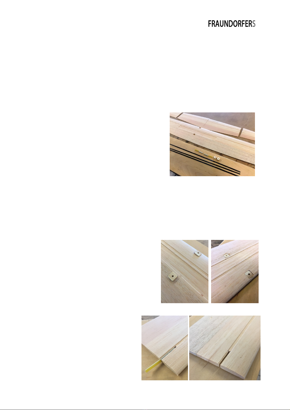
The 5 main wing parts are CNC milled and we
therefore recommend to give them a light
sanding with a 240 grit sandpaper. The
dihedral at the joints is already set and mustn't
be altered.
First cut the 3 carbon strips (5.8 x 0.6) to the correct length (2 for the main
wing panel and 2 for each inner tip). The strips must fit exactly into slots of the
3 wing panels and should not overlap them!
Now completely open up the milled openings in the main wing panel for the
screw connection inlets, which is best done with a sharp carpet knife. Sand one
side of the prepared carbon strips (120 grit sandpaper ).
Try to fit the 2 plywood wing-inlets into the
milled recesses in the main wing panel. If
they don't fit in easily sand the edges until
you get a perfect fit. Now glue them into
the recesses with the glue of your choice
(epoxy/wood glue). It's important that the
glued in inlets flush with the wing surface!
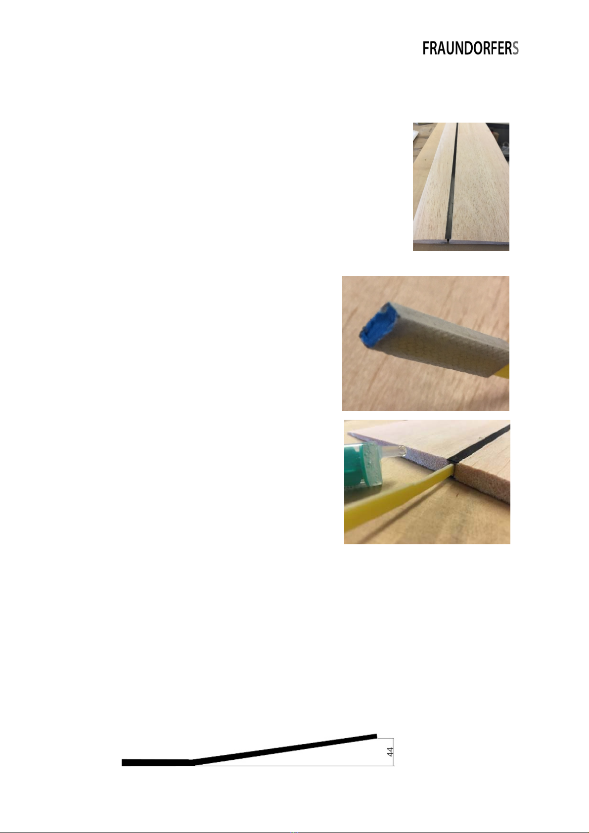
Put the joiners (2 mm glass fiber)
into the joiner bags (they will be
later on glued into the wing panels
between the wing reinforcement
carbon strips) and cut out a recess in
the center of the milled channel of
the main wing panel (joiner bag) and
the tip (only for the joiner!). Make

6
sure that the joiner bags and the joiner fit into the recess easily but without
movement.
Next clue the prepared carbon strips in the milled channels
of the main wing panel. For this you best use epoxy or a
low viscosity super-glue.
Before you glue (Epoxy) the joiner bags and
the joiner into the main wing panel you have
to sand (120 grit sandpaper) both parts
slightly to assure a proper bond. In addition
close the joiner bag on the end which is glued
into the main wing panel with some modelling
clay (Play-Doh 'borrowed' from your kid works
as well) or wax to avoid epoxy running into it.
Now glue (epoxy!) the joiner bags into the
main wing panel. Make sure that the joiner
bag has good contact with the balsa (left- and
right-side) as well as the carbon strips (top and
bottom).
Now clue the carbon strips (as you have done
with the main wing panel) in both inner tips.
For the next steps we don't recommend to do both sides in parallel.
Give the joiners on the side which will be glued into the tip a light sanding to
(120 grit sanding paper) to get a proper bond when gluing them into the tip.
Slide the joiner into the joiner bag of the main wing panel). Now put some
Epoxy into the cut out slot of the tip and slide the tip onto the joiner. There
shouldn't be a gap now between the main wing panel and the tip (Do a 'dry fit'
in advance) . To assure the proper dihedral lay a 44mm balsa block under the
end of the tip and let the Epoxy cure. Repeat the steps for the other side.

7
The joiner is the only connection between the main wing panel and the tips.
The two panels will be secured with crystal tape for flying. Although not
needed an additional hesitation pin can of course be installed by yourself.
Remove the tips from the main
wing panel. Now you can glue
the outer tips on the inner tips.
This is also best done with Epoxy.
To assure the correct dihedral
put a 85mm balsa block under
the end of the outer wing panel
while curing.
For the spoiler linkage, glue (or tape) the servo to the bottom
side of the wing. For the linkage itself use a 0.5 mm steel wire.
Lightly sand all wing surfaces (especially the glued joints and the carbon
reinforced areas) to get a smooth surface. Now the wing is ready to get
covered with the foil of your choice.

8
Rudder and Elevator
First remove all balsa parts from the 3mm balsa sheet, then align the vertical
tail fin and the vertical tail rudder and tape
them together with masking tape. Give both
ends a light sanding before gluing the top and
bottom tip to the vertical fin. Do the same with
the Elevator. All tips (Rudder and Elevator) are
slightly longer than needed. Glue them flush
with the leading edges of the rudder and
elevator. After the glue dried you can sand the
overlaying parts of the tips flush with the trailing edges of the rudder and
elevator.
Now cut a piece in the length of the milled slot in the elevator from the 200 x
2.9 x 4 mm carbon strip and press it into the slot (vertically) and glue it in with
thin super glue. Next dry fit the 3mm plywood inlet for the elevator mounting
screw (the edges may need some light sanding). When you have tight flush fit
you can glue the inlet into the elevator.
Carefully sand the elevator from the hinge line to the trailing edge to get a
'sharp' (1.5mm) trailing edge. To have the elevator mounting screw (2.9 x 18
mm) as flush as possible with the elevator bevel the inlet a tiny bit.
As a last step cut the elevator along the hinge line in two (do not cut through
the tips!) and sand an angle into the moving bit allowing a down elevator
movement of 10mm.

9
Fuselage
Prepare all parts of the fuselage.
First put the bottom 4mm plywood part (milled slots facing up) on your (flat)
building board. Glue in the spars onto the
fuselage bottom (the numbers and
positions can be taken from the drawing
of the wooden parts in chapter 3). Make
sure that the spars are at right angles and
flush on both sides with the bottom part.
Lightly sand the joint of the spars and the
bottom on both sides.
Next you need the two sides of the fuselage as well as two 2 x 2mm balsa strips
and the 2mm balsa parts with the cut out
section of the wing underside. Mark the
positions of the spars with a pencil on the
side parts (make a left and a right one!).
Glue the 2 x 2mm balsa strips with an offset
of 2 mm from the top edge onto the front
part of the fuselage sides (the balsa strips
will support the cover plate at a later
stage). The 2mm balsa parts for the wing
support must be glued flush with the top edge of the side panels (again, make
sure that you have a left and right side!).
Now you can glue one side to the bottom/spar construction.

10
Put a drive-in nut from below into the parts SH-VO (VO = vorne = front) and SH-
HI (HI = hinten = back) and secure them with epoxy or super glue. SH-VO and
SH-HI can now be glued onto the side panel and spar (must be parallel to the
fuselage bottom).
Glue now the 2nd side panel to the fuselage. The next step is to sand the edges,
glue joints and the font- and back-most spar.
For the nose you first must glue the 12mm balsa parts together before you can
glue the whole balsa block on the fuselage. Sand until you have a nice shape.
Dry fit the 2mm balsa cover plate and – if needed – slightly trim it to get a nice
fit.
The cover plate is secured with a 2mm balsa piece in front and a magnet on the
back. Glue the magnet in the cut of spar no. 3 and the M4 washer centered on
the underside of the cover plate. Make sure that the washer is flush with the
end of the cover plate.
Draw a center line with a pencil on the underside of the cover plate. Take the
small 2mm balsa piece and round the edges and corner on the nose facing side.

11
Now glue the piece onto the cover plate. To do center the 2mm balsa piece on
the center line with an overlap of +/- 4mm on the front of the cover plate. Put a
small once folded paper in the front part between the cover plate and the balsa
piece to get a slight angle.
Tail-Boom
You need a long ruler or square profile (ca. 1m) to correctly mount the tail-
boom!
Put the fuselage alongside the ruler and
slide the tail-boom through the openings in
spar 1 and 2. Mark the positions of the
spars on the boom with a pencil and take
the boom out again. Sand the marked
areas on the boom to get a proper glue
joint later. Put the boom back in the
fuselage and slide the 4mm plywood
mounting gauge from the back onto the boom (the arrow on the gauge must
point towards the bottom edge of
the square profile/ruler).
Now you can put the rudder into
the slot of the tail boom. Make
sure that the rudder is exact
square to the table. Now the
boom is perfectly aligned and can be
glued to the fuselage. You best use
Epoxy to do this.
The next building step is the mount of
the support pylon for the elevator.
Take the 3 needed piecses (1 x 4mm
plywood; 2 x 2mm balsa). There is an
arrow on the plywood part which must point to the nose of
your plane. Mark the nose pointing end with a pencil on top
to know the nose facing end after gluing on the 2mm balsa parts (important for
the correct angle of incidence). Now you can glue the balsa parts onto the
plywood (Super Glue) and round the front- and backside with sanding paper.

12
While doing this take care to not sand the two wooden pins on top as they are
needed to center the elevator.
No wrap some sanding paper around the boom (ca. 6 to 8 cm in front of the
rudder slot) no gently sand the pylon bottom to the shape of the boom.
Now we suggest to cover the pylon and the elevator with the fabric of your
choice.
Put the elevator on the pylon and fix it with the 2.9 x 13mm screw. Also mount
the wing onto the fuselage. Align the elevator with the wing center panel and
glue the pylon on the boom (Epoxy). The distance between the rudder and the
trailing edge of the elevator should be approximately 10mm.
Slide the rudder into the slot and make sure that the two marks on the rudder
align with the boom. Additionally make sure that the rudder hinge line is
exactly vertical. When achieved you can glue (Super Glue or Epoxy) the rudder
to the tail boom (if everything was done properly before you should have an
exact angle of 90 degrees between elevator and rudder). The rudder can now
be covered.
As a last step you need to bend two ca. 5cm long springs out of the 0.5mm
wire. The torsion angle should be +/- 100 degrees.
Mount the springs to the rudder and elevator.

13
RC installation
The RC installation can now be done as you like best.
We recommend the following components:
Servos: 3x Dymond D47 (Robbe FS31)
Receiver: as small as possible
Battery: LiPo 300mAh 2S
Settings
CoG: 73 – 78mm behind the leading edge
Deflections Elevator: + 8 / - 4 mm
Deflections Rudder: as much as possible
Brake: 0 – 60 Degrees
Tow hook position: Approximately CoG
I wish you a lot of fun with the MADRES.
If you have any questions or suggestions
for improvement, don’t hesitate to contact
me!
Fa. Stefan Fraundorfer
Phone: 0043 699 11332941
This manual suits for next models
1
Table of contents