Frederick Crowther & Son Cromar Manual

CROMAR
FREDERICK CROWTHER AND SON LTD
EST 1962
Swarf Management and Coolant Filtration Systems
Operation & Maintenance Manual
Frederick Crowther & Son Ltd.
Locksley Works, Armytage Road Industrial Estate, Brighouse, West Yorkshire HD6 1QF
Tel. +44 (0) 1484 400200 Fax. +44 (0) 1484 728088
Email: sales@cromar.co.uk www.cromar.co.uk

CROMAR
Health and Safety
This manual contains instructions intended for the user’s daily work with the equipment.
This manual must always be available to the individual or individuals working with the equipment.
It is important to ensure that:
• The manual and other applicable documents are retained for the entire service life of the
equipment
• The manual and other applicable documents are included as part of the equipment
• This manual is passed on to other users of the equipment
• This manual is updated if any supplements or amendments to the equipment take place
• This manual describes the methods applied when using the equipment.
Safety code
• Before you start using the equipment and carrying out maintenance or servicing on this
equipment, please read through the applicable parts of the instruction
• Assume all electrical equipment is live
• Assume all hoses and pipelines are pressurised
• When servicing and maintaining the equipment/machine, ensure that the electrical supply is
disconnected and the pressure in pipes and hoses is released in a controlled manner
• Servicing and maintenance must be carried out by authorised service and maintenance
staff only
• Use only spare parts approved by Frederick Crowther & Son Ltd
• Make sure that the machine is securely mounted and installed in accordance with instructions
before starting it
• Use the machine only for the intended use
• In the event of abnormal vibration or noise – stop the machine and consult the manual
• Electrical installation must be carried out by an authorised electrician only
• Tanks must be drained of cutting uids before any lifting operations are carried out.

CROMAR
Page 51
5. High Pressure Coolant System
High Pressure Unit Media Free Unit
For illustration only.
5.1 Transportation
General
High Pressure Coolant Systems should only be moved by trained personnel,
competent in crane operation and slinging.
Do not stand under the moving unit! Always use the equipment included for lifting and
transport.
5.1.1 With Fork Lift Truck
Transport only on the original wooden pallet supplied. Ensure equipment is secured
against falling or slipping.
5.1.2 With Crane
Lift using existing lifting points.
Note :- The net weight is displayed on the name plate located on the twin towers.
5.1.3 Where applicable, High Pressure Systems are tted with castors to assist with nal
positioning.

CROMAR
Page 52
5.2 Installation
5.2.1 Controls
Incorporated in Parent Machine Controls
The conveyor should always be running, during all cutting operations to ensure the
High Pressure Coolant System operates efciently. If automatically stopped by
interlocks etc. for safety reasons the conveyor must be restarted when cutting
recommences.
5.2.2 Control of the High Pressure Coolant System
The High Pressure Coolant System is directly controlled by MDI signal from the
machine tool or through manual operation if required. All alarms are monitored on the
unit and through the machine controller or on the High Pressure unit itself.
5.3 Mechanical
The unit should be manoeuvred into the most appropriate operating position.
5.4 Electrical
Interlocking with the machine access door stops the High Pressure Coolant system
when the door is opened. All wiring should conform to the latest harmonised European
standards or IEE regulations.
5.5 Maintenance
5.5.1 Thermal Trip Alarm
If either the thermal protection breakers (for the High Pressure supply pump or the low
pressure transfer pump) trips out, this alarm will appear on the screen and a signal will
be sent to the machine controller as a ‘thermal trip’ alarm.
The panel beacon will also ash.
This condition should then be investigated and rectied.
5.5.2 Coolant Level Low Alarm
If the coolant level drops below that shown as low level on the accompanying drawing,
this alarm will appear on the screen and a signal will be sent to the machine controller
as a ‘coolant level low’ alarm.
The panel beacon will also ash.
In this condition the High Pressure pump will not be allowed to run. This condition
should then be investigated and rectied.

CROMAR
Page 53
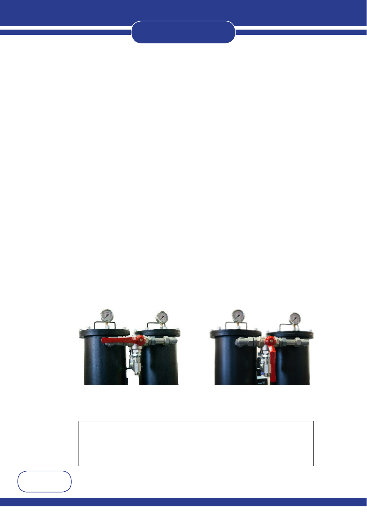
5.5.3 Filter Blocked Alarm
(Not applicable to Media Free System)
A pressure switch monitors the ow of coolant entering the HP tank through the lter
unit and has been preset to activate when the back pressure rises to a certain setting.
If the switch activates then the lter blocked alarm will appear on the screen and a
signal will be sent to the machine controller as a ’Pressure alarm’.
The panel beacon will also ash.
Please be aware that the reason may be a blocked lter or may be due to lack of
coolant in the main machine tank which would also result in a low ow of coolant
passing through the lter.
This condition should be investigated and the appropriate action taken.
Refer to the enclosed procedure for switching over the lter and for changing the lter bag.
5.5.4 Pressure Switch Error Alarm
(Not applicable to Media Free System)
If the pressure switch shows a coolant pressure when the transfer pump is not running
then the pressure switch error alarm will appear on the screen.
The panel beacon will also ash.
This indicates there is a fault with the ow switch which should be investigated and
may require replacement of the switch unit.
5.5.5 Alarm Reset Procedure
The four alarms already mentioned are of the latched on type.
If any alarm is activated, the alarm message and the signal back to the machine
controller will remain on, even if the condition clears itself.
To clear an alarm from the system, rst ensure the cause of the alarm has been
rectied, then follow the instruction from the main screen -
Press ‘Menu Page’
Press ‘Alarm Page’ - to show the active alarm which will be ashing red
Press ‘Ack’ - the alarm will turn to green (unless the condition still exists)
Press ‘Exit’ - to return to the Menu Page
Press ‘System Reset’ - to return the system back to normal operation
Press ‘Exit’ - to return to the title screen
Any alarms still active will remain even after pressing the reset.
5.5.6 Coolant System Alarm
If the thermal protection breaker on the 24V DC supply for the high pressure coolant
unit trips out, an alarm signal will be issued to the machine controller using the
‘Coolant system Alarm’.
The condition should then be investigated and rectied.

CROMAR
Page 54
5.5.7 Transfer Pump Manual Fill
If this button is held in, the coolant transfer pump will begin to operate.
When it is released the system will return to normal automatic control.
Whilst the button is held in the coolant level control will not be active and hence it is
possible to overll the tank, thus care should be taken.
This facility is supplied to assist in initial lling of the system and should generally not
be needed in normal operation.
5.5.8 Filter Change Over Procedure
(Not applicable to Media Free System)
Dual Filters
1. When the lter becomes blocked the pressure switch detects a rise in pressure
and sends a signal giving you a lter block alarm.
2. Simply change the 3-way valve while the system is running to the standby lter,
which will allow the machine to continue running, and allow you to change the
blocked lter at a later date.
3. Remove the lter lid on the non-active lter taking care not to dislodge the ‘O’ ring
seal.
4. Remove the clamp ring and the dirty lter bag and replace with new bag
5. Replace the clamp ring and the lter lid
6. The lter is now ready for use
Handle left Handle down
- left hand lter is being fed - right hand lter is being fed.
REPLACEMENT FILTER BAGS ARE AVAILABLE FROM
FREDERICK CROWTHER AND SON LTD
BRIGHOUSE WEST YORKSHIRE
TEL 01484 400200 FAX 01484 728088
QUOTING PART No 88010019

CROMAR
Page 55
4
9
2
3
5
1
7
6
5
8
Item Number
1
2
3
4
5
6
7
8
9
Description
High Pressure Tank Body
Twin Towers
Tank Top Plate
Control Panel Mounting Bracket
Lifting Lugs
Coolant Level Sensor
Castors
Electrical Controls
High Pressure Pump
High Pressure Unit Assembly

CROMAR
Page 56
4
9
2
3
11
5
7
8
10
1
12
15
6
15
16
14
13
Media Free Unit Assembly
Item Number
1
2
3
4
5
6
7
8
9
10
11
12
13
14
15
16
Description
Tank Main Body
Support Frame
Swarf Tray
High Pressure Pump
Tank Top Plate
Conveyor Top Plate
Hydrocyclone
Hydrocyclone Adaptor
Drive Assembly
Motor Assembly
Return End Assembly
Level Sensor
Castors
Plug
Lifting Lug
Electrical Controls
14

CROMAR
Page 57
5.6 Trouble Shooting
WARNING!
High Pressure Unit should be shut down and electrically isolated prior to any
corrective actions.
Electrical maintenance and repairs to be carried out by suitably qualied electrical
personnel only.
Problem Symptoms Action
5.6.1
High Pressure Coolant
System does not start.
Loose wire.
Overload trip.
Check all wiring contacts.
Reset overload.
Check all emergency stops
are reset.
Check all interlocks.
Check machine is operating
through MDI.
Table of contents
Popular Laboratory Equipment manuals by other brands

Ocean Insight
Ocean Insight FLAME-NIR+ Installation and operation manual

Fisher Scientific
Fisher Scientific Isotemp 20LFEEFSA Instruction and operation manual

GE HEALTHCARE
GE HEALTHCARE HiPrep 16/10 CM FF instructions

R-Biopharm
R-Biopharm RIDA qLine Scan user manual

Struers
Struers LaboDoser-100 instruction manual

ThermoFisher Scientific
ThermoFisher Scientific thermo scientific imPULSE S.U.M. user guide