MRC WBT-200 User manual

3, Hagavish st. Israel 58817 Tel: 972 3 5595252, Fax: 972 3 5594529com.mrclab@mrc
Operation Manual
Digital Water Bath Shaker
WBT-200
This unit is water bath shaker for professional, industrial, or educational use
where the preparation or testing of materials is done at approximately
atmospheric pressure and no flammable, volatile or combustible materials are
being heated.
MRC LTD.
Hagavish 3 st.
HOLON 58817
ISRAEL
Tel (+972)-3-5595252
Fax (+972)-3-5594529
Website: www.mrclab.com

3, Hagavish st. Israel 58817 Tel: 972 3 5595252, Fax: 972 3 5594529com.mrclab@mrc
Section 1
INTRODUCTION
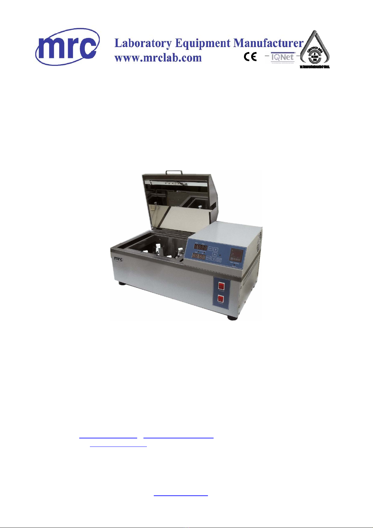
Thank you for choosing a water bath shaker. This unit is not intended for use
at hazardous or household locations. Before you use the unit, read this entire
manual carefully to understand how to install, operate, and maintain the unit in
a safe manner. Your satisfaction with the unit will be maximized as you read
about its safety and operational features.
Keep this manual on-hand so it can be used by all operators of the unit. Be
sure all operators of the unit are given appropriate training before you put the
unit in service.
Note: Use the unit only in the way described in this manual. Failure to follow
the guidelines and instructions in this manual may be dangerous and illegal.
General Safety Considerations
Your water bath shaker and its recommended accessories have been
designed and tested to meet strict safety requirements.
For continued safe operation of your water bath shaker, always follow basic
safety precautions including:
Read this entire manual before using the water bath.
Be sure you follow any city, county, or other ordinances in your area
regarding the use of this unit.
Use only approved accessories. Do not modify system components.
Any alterations or modifications to your water bath may be dangerous
and will void your warranty.
Always plug the unit’s power cord into a grounded electrical outlet that
conforms to national and local electrical codes. If the unit is not
grounded, parts such as knobs and controls may conduct electricity
and cause serious injury.
Do not connect the unit to a power source of any other voltage or
frequency beyond the range stated on the power rating overlay at the
rear of the unit.
Do not modify the power cord provided with the unit. If the plug does
not fit an outlet, have a proper outlet installed by a qualified electrician.
Avoid damaging the power cord. Do not bend it excessively, step on it,
place heavy objects on it. A damaged cord can easily become a shock
or fire hazard. Never use a power cord after it has become damaged.
Do not position equipment in a manner that prohibits access to power
cord.
Do not attempt to move the unit during operation or before the unit has
been allowed to cool.

3, Hagavish st. Israel 58817 Tel: 972 3 5595252, Fax: 972 3 5594529com.mrclab@mrc
Section 2
RECEIVING YOUR UNIT
Before leaving our factory, all units are packaged in high quality shipping
materials designed to provide protection from transportation related damage.
Once a unit leaves our factory, however, safe delivery becomes the
responsibility of the carrier who is liable for loss or damage to your unit.
Damage sustained during transit is not covered under your unit warranty.
When you receive your unit, inspect it for concealed loss or damage to its
interior and exterior. Should you find any damage to the unit, follow the
carrier’s procedure for claiming damage or loss.
Inspection Guidelines
Carefully inspect the shipping carton for damage. If the carton is damaged,
report the damage to the carrier service that delivered the unit.
If the carton is not damaged, open the carton and remove its contents.
Carefully check all packaging before discarding. Save the shipping carton until
you are sure everything is in order.
Returning Shipment
If you must return the unit for any reason, first contact your service
representative for authorization. You will be asked to provide the data plate
information. See Recording Data Plate Information.
Recording Data Plate Information
Once you have determined the unit is free from damage, locate the data label
at the back of the unit. The data label indicates your unit’s model number and
serial number.

3, Hagavish st. Israel 58817 Tel: 972 3 5595252, Fax: 972 3 5594529com.mrclab@mrc
Section 3
INSTALLATION
Your satisfaction and safety require a complete understanding of this unit.
Read the instructions thoroughly and be sure all operators are given adequate
training before attempting to put the unit in service.
This equipment must be used only for its intended application; any alterations
or modifications will void your warranty. Local city, county, or other ordinances
may govern the use of this equipment. If you have any questions about local
requirements, please contact the appropriate local agency. The end user may
perform installation.
Customer service should be contacted for operating conditions outside these
limits.
Environmental Conditions
Under normal circumstances these units are intended for use indoors, at room
temperatures between 18ºC and 40ºC, at no greater than 80% relative
Humidity (at 25ºC) and with a supply voltage that does not vary by more than
10% from the data plate rating.
Power Source
Check the data label for voltage, cycle, and ampere requirements. If matched
to your power source, plug the power cord into a grounded outlet.
Voltage should not vary more than ± 10% from the data label rating.
These units are intended for 50HZ application. A separate circuit is
recommended to prevent damage to the unit due to overloading or circuit
failure.
Location
In selecting a location, consider all conditions that might affect performance,
such as heat from radiators, ovens, autoclaves, etc. Avoid direct sun, fast-
moving air currents, heating and cooling ducts, and high traffic areas. Allow a
minimum of 30 cm between the unit and any walls or partitions that might
obstruct free airflow.

3, Hagavish st. Israel 58817 Tel: 972 3 5595252, Fax: 972 3 5594529com.mrclab@mrc
Lifting and Handling
These units can be heavy for some people and care should be taken to use
appropriate lifting devices that are sufficiently rated for these loads. Units
should only be lifted from their bottom surfaces. Handles and knobs are not
adequate for lifting or stabilization. The unit should be completely restrained
from tipping during lifting or transport.
All moving parts such as trays or covers should be removed during transfer to
prevent shifting and damage.
Cleaning and Decontamination
In the event hazardous material is spilled onto or into the equipment
appropriate decontamination must be carried out. If there is any doubt about
the compatibility of decontamination or cleaning agents with parts of the
equipment or with material contained, please contact the manufacturer.
Units are cleaned at the factory, but not sterilized. Remove any racks if
assembled and clean the bath with a disinfectant that is suitable for your
application. See Maintenance Section for cleaning instructions and
precautions.

3, Hagavish st. Israel 58817 Tel: 972 3 5595252, Fax: 972 3 5594529com.mrclab@mrc
Section 4
CONTROLS AND COMPONENTS
OVERVIEW
Power Switch
The Red (On/Off) power switch, located in the bottom right hand corner of the
control panel, controls all power to the unit. It must be in the I position to be
ON and illuminated before any systems are operational. The on/off switch
must remain easily accessible at all times.
Shaker Switch
The Red (On/Off) shaker switch, located above the power switch, controls the
power to the shaker. It must be in the I position to be ON and illuminated to
operate the shaker.
Bath Cover
Using the bath cover supplied with your accessories will accelerate heat-up
time and reduce evaporation.
The cover must be used to reach set points above 60ºC. The bath cover is not
designed to be airtight and create a pressurized environment.
Water level indicator
The water level indicator is indicating the water level in the tank to avoid
damages to the heating element.
If the LED is lit, it is indicate that the tank is empty or there is not enough
water in the tank

3, Hagavish st. Israel 58817 Tel: 972 3 5595252, Fax: 972 3 5594529com.mrclab@mrc
Fill water minimum until the LED is OFF or fill more water above the minimum
permitted
Remember that if the tank is empty or if the water level is too low, the heating
process will not start.
Internal parts overview

3, Hagavish st. Israel 58817 Tel: 972 3 5595252, Fax: 972 3 5594529com.mrclab@mrc
Main Temperature Controller
This control is marked TEMP. CONTROL and consists of the digital display
and UP and DOWN arrow pads for inputting set point temperatures and
calibration.
PV- display of actual temperature inside cabinet.
SV- Set-up temperature indicator.
AT- Automatic Calculation P.I.D
OUT-Control system output indicator
ALM- Over-temperature protection indicator.
Once the indicator is lit, it means the temperature is over the set-up
temperature range for protection.
SET-If there is a temperature change, push this button first.
Then there is a 4-digit number shown on SV, and one of the lamps will be lit.
The lamp can be used to set up the temperature. To push ◄button to move
left, and ▲button to increase, ▼button to decrease.

3, Hagavish st. Israel 58817 Tel: 972 3 5595252, Fax: 972 3 5594529com.mrclab@mrc
Shaker Controller

3, Hagavish st. Israel 58817 Tel: 972 3 5595252, Fax: 972 3 5594529com.mrclab@mrc

3, Hagavish st. Israel 58817 Tel: 972 3 5595252, Fax: 972 3 5594529com.mrclab@mrc
Section 5
OPERATION
Warning: This bath is not intended for use as acid baths. Use as an acid bath
will cause severe damage to bath components and void your warranty. Do not
use deionized water, tap water, or chemicals. USE DISTILLED WATER
ONLY.
Turning On the Unit
To turn on the unit, perform the following steps:
1. Check power supply against unit serial plate; they must match.
2. Plug service cord into the electrical outlet. If supplied with a detachable
cord set, plug the female end into the unit inlet and the male plug into the
power supply. 3. Fill bath to your required depth with DISTILLED WATER
until the indicator LED is OFF or fill more water above the minimum permitted
but not too much to avoid overflow during the shaking process.
DO NOT USE TAP WATER, DEIONIZED WATER, OR CHEMICALS. Check
water level frequently, add water to appropriate levels if needed. At higher
operating temperatures, or under circumstances where a cover cannot be
used, it will be necessary to check the water level more frequently.
4. Push the Main power switch to the ON position.
Bath Cover
Using the bath cover supplied with your accessories will accelerate heat-up
time and reduce evaporation.
The cover must be used to reach set points above 60ºC. The bath cover is not
designed to be airtight and create a pressurized environment.
Setting Main Temperature Control
To enter set point mode on the control, push and release either the UP or
DOWN arrow pad one time and the digital display will start to blink. While
blinking, the digital display shows the set point that can be changed using the
UP or DOWN or LEFT arrow pads to change the temperature setpoint and
press on the SET button one time to confirm.
Allow at least two (2) hours for the temperature to stabilize.
Never turn on the unit if the tank is empty from water or if the
water level is too low

3, Hagavish st. Israel 58817 Tel: 972 3 5595252, Fax: 972 3 5594529com.mrclab@mrc
Calibrating the Main Temperature Control (OFFSET)
We recommend that you calibrate your unit if needed and after the chamber
temperature has been stable at the set point for several hours.
1. Place a calibrated reference thermometer in the bath. Allow the
thermometer to reach temperature and remain stable for one (1) hour.
2. Compare the reading on the reference thermometer with the temperature
control display. If there is a difference, put the display into calibrate mode by
pressing and holding the SET pad for 3 seconds until the "AL" will be shown.
Press several times on the SET pad until "LoCK 1".
Change the value from 1 to -1 with the DOWN pad and press one time on the
"SET" pad to confirm.
Press several times again on the "SET" pad until "bs"
3. Press the UP or DOWN arrow pad to adjust the display to match the
reference thermometer. If the arrow pads are not pressed within 1 min (60)
seconds the display will revert to showing the temperature within the bath.
4. Allow the unit to stabilize again, and repeat calibration if necessary.

3, Hagavish st. Israel 58817 Tel: 972 3 5595252, Fax: 972 3 5594529com.mrclab@mrc
PID Auto tuning (AT)
The P, I and D terms need to be "tuned" to suit the dynamics of the process
being controlled.
Temperature control using digital PID controllers have automatic auto-tune
functions. During the auto-tune period the PID controller controls the power to
the process and measures the rate of change, overshoot and response time
of the plant. This is often based on the Zeigler-Nichols method of calculating
controller term values. Once the auto-tune period is completed the P, I &D
values are stored and used by the PID controller.
We recommend doing this AUTO TUNE if there is a temperature overshooting
above your set point
1. Pressing and holding the "SET" pad for 3 seconds until the "AL" will be
shown.
2. Press several times on the "SET" pad until "AT OFF".
3. Change "OFF" to "ON" with the "DOWN" pad and press one time on the
"SET" pad to confirm.(the "MAN" LED will be light on or blinking)
Press and hold "SET" pad for 3 second to revert to showing the temperature
within the bath
4. If the arrow pads are not pressed within 1 min (60) seconds the display will
revert to showing the temperature within the bath.
During the AT process, do not touch the controller or turn off the unit
until AT procedure will be finished.

3, Hagavish st. Israel 58817 Tel: 972 3 5595252, Fax: 972 3 5594529com.mrclab@mrc
Section 6
MAINTENANCE
Warning: Prior to any maintenance or service on this unit, disconnect the
power cord from the power supply and empty the water from the tank. Before
connecting the unit to its power supply, be sure all volatile and flammable
cleaners are evaporated and dry.
Draining Tank
1. Position the left side of the water bath over a sink or appropriate receptacle
large enough to hold the quantity of water.
Cleaning
1. Clean the water bath with mild soap and water solution. DO NOT USE
chlorine-based bleaches, as they will damage the tank interior. DO NOT USE
spray cleaners that may contain solvents, which could leak through openings
and cracks and harm electrical part coatings. Failure to do this may
permanently damage the unit.
2. Rinse the water bath with clean water and wipe dry with a soft cloth.
Stainless steel does not rust, but foreign materials in the tank may rust or
leave rust spots. If corrosion is seen, scrub out the stains with a mild abrasive,
never steel wool.
Storage
If the unit is to be shut down for an extended period of time, the tank must be
emptied and cleaned as described above. No adjustments to controls should
be necessary when the unit is put back in service.
If you are shutting the unit down for transport, perform the following steps:
1. Turn the unit off.
2. Disconnect from the power supply.
3. Remove the bath cover.
4. Empty and clean the tank.
5. Please see Lifting and Handling for further instruction.
6. No maintenance is required on any of the electrical components.

3, Hagavish st. Israel 58817 Tel: 972 3 5595252, Fax: 972 3 5594529com.mrclab@mrc
Section 7
SCHEMATICS
Table of contents
Other MRC Laboratory Equipment manuals
Popular Laboratory Equipment manuals by other brands

Dionex
Dionex UltiMate 3000 Applications

PBI
PBI Barocycler 2320EXT Operator's manual

Accu-Scope
Accu-Scope EXC 350 manual

Koehler
Koehler K12212 Operation and instruction manual

Thermo Scientific
Thermo Scientific Thermo Scientific SL Plus Series Instructions for use

Beckman Coulter
Beckman Coulter Avanti J Series Instructions for use

SMC Networks
SMC Networks INR-244-780 Operation manual

Blue-White industries
Blue-White industries C-600P manual

Steinberg Systems
Steinberg Systems SBS-LZ-3000SLS user manual

Tektronix
Tektronix P7350SMA instruction manual

Sartorius Stedim Biotech
Sartorius Stedim Biotech BIOSTAT CultiBag RM 600 operating manual

DORIC
DORIC Fiber Photometry System Getting started guide