SPECIFICATIONS
INPUT/OUTPUT JACK PANEL
IN Terminal
Input terminal for each loop. Connect your guitar, etc. to
this jack.
SEND (N.C) Terminal
Send terminal of effect loop. Used to send signals to an
effects unit, amplifier, etc. The signal fed to the IN terminal
appears here when this loop is turned on and the signal is
muted when this loop is turned off.
This terminal can be used as a control terminal (normally
closed) to switch amplifier channels, etc. The tip and ground
in the jack are connected when the loop is turned off.
RETURN Terminal
Return terminal of effect loop. Used to receive signals
from an effects unit, guitar, etc.
OUT (N.O) Terminal
Output terminal to supply the signal after passing through
the effect loop. The signal fed to the RETURN terminal
is output from this terminal when the loop is turned on.
The signal fed to the IN terminal is output when the loop
is turned off.
This terminal can be used as control terminal (normally
open) to switch amplifier channels, etc. The tip and ground
in the jack are connected when the loop is turned on.
C1/C2 Terminal
Connect a latch type switch to this terminal to control
turning on/off of the respective loop. Since it is a stereo
phone jack, LOOP1 is turned on when the tip is connected
to the ground and LOOP2 is turned on when the ring is
connected to the ground.
NOTE: Inserting a standard mono plug in this terminal
automatically turns on the LOOP2 terminal but this will
cause no problem in actual usage. On/off control of the
LOOP2 becomes available by inserting a plug in the
LOOP2 control terminal (C2).
C2 Terminal
Connect a latch type switch to this terminal to control
turning on/off of the loop. Since this is a mono phone
jack, LOOP2 is turned on when the tip is connected to
the ground.
ON/RMT Selection Switch
When this switch is set to the RMT side, the switch
connected to the control terminal can be used to turn on/
off the respective loop.
When this switch is set to the ON side, the respective loop
is forcibly turned on irrespective of the status of the switch
connected to the control terminal.
POWER DC 9V IN Terminal
Power Indicator
This LED illuminates when the LB-2 is properly powered.
Loop On Indicator
This LED illuminates when the corresponding loop is
turned on.
Table of Contents
1 Controls and Indicators: Terminal Panel .. .. ........................................................................................... 5
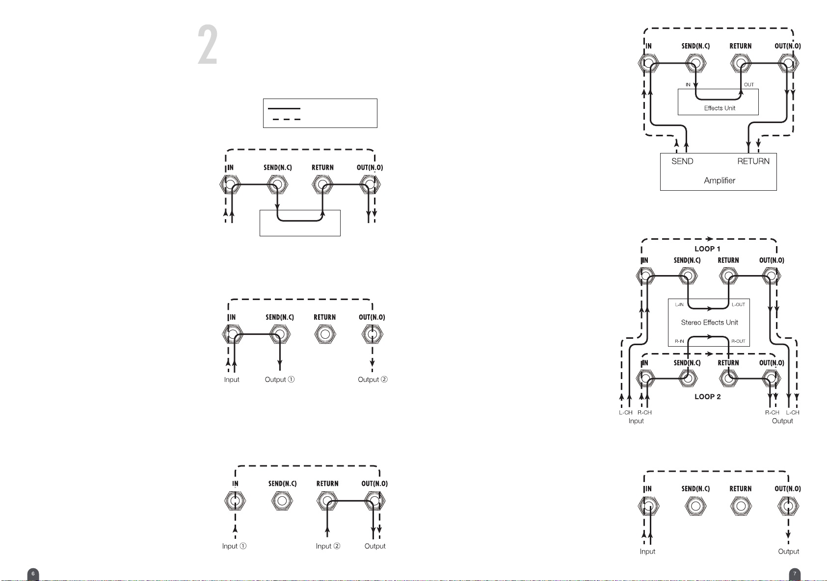
2 How to Use Loops .. .. ............................................................................................................. ..... 6
2-1 As Effect Loop .. .. ............................................................................................................. .... 6
2-2 As Output Selector.. .. ............................................................................................................. 6
2-3 As Input Selector.. .. ............................................................................................................... 6
2-4 As Amplifier’s Send/Return Effect Loop .......................................................................................... 7
2-5 As Stereo Effect Loop ............................................................................................................. 7
2-6 As Mute Box.. .. ............................................................................................................. ....... 7
Specifications
• Number of Loops: 2 (two separated loops)
• Control: ON, RMT (remote)
• Terminals:
9 x 1/4” standard phone jack (input, output, control)
1 x 1/4” standard TRS phone jack (control)
1 x 9V DC input jack (for connecting AC adapter)
• Power supply: 9V DC center negative polarity
For USA: FA-0905D-JA
For UK: FA-0905D-UK
For Europe: FA-0905D-EU
• Consumption current: 75 mA (max.)
• Dimensions (W x D x H, incl. protuberances such as jacks): 145 x 59 x 49 mm (5.7 x 2.3 x 1.9 inches)
• Weight (excl. AC adapter): 230 g (0.51 lbs)
• Accessories: Warranty card, Owner’s manual, 4 x rubber foot (No connecting cable included)
* Specifications and appearance subject to change without notice.
• Two completely independent loops
• With separate loops, it can be used as an input/output selector (refer to application examples)
• All of the input/output jacks and controls are mounted on one side to reduce wiring space within a pedalboard
or rack
• Durable plastic molded phone jacks adopted for prolonged use.
Main Features of LB-2
Any AC adapter that has regulated 9V DC output, center
negative polarity, and more than 75mA power supply
capability can be used. A standard 5.5 x φ2.1mm plug
is acceptable.