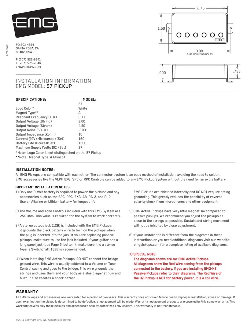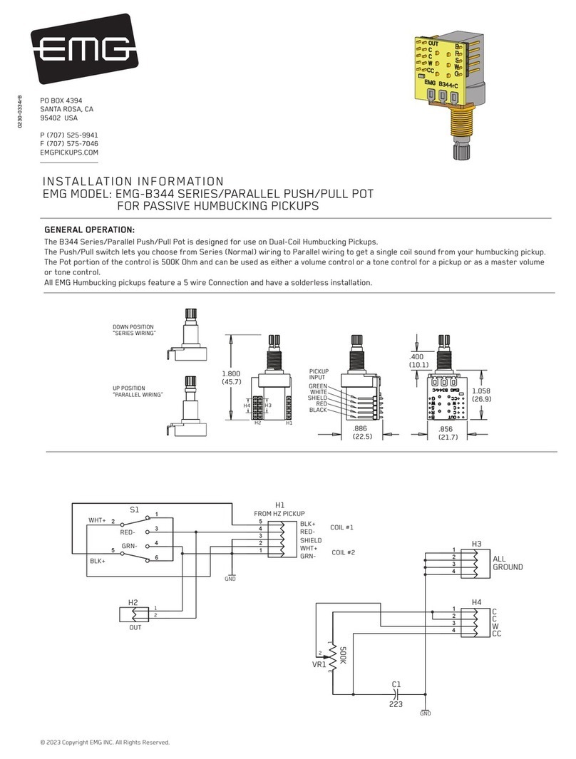
INSTALLATION:
B289 and B348
Toggle Switches
All EMG Solderless Toggle Switches use the same “BNOG” wiring scheme:
B= Bridge Pickup input (White wire)
N= Neck Pickup input (Red wire)
0= Output of Switch (Black wire)
G= Ground (Bare shield)
Install the 4 pin connector housing on the switch as shown
in the diagram to the right. Install the 2 separate 2 pin connectors
on to the 4 pin connector between the black and red housings as shown.
The black and green terminal blocks will not be used for the switch.
Reverse this connector to
make the switch work in
the opposite direction
B289
B348
1234
5
6
7
8
GROUND
BRIDGE P/U
NECK P/U
OUTPUT
INSTALLATION:
Hardwired 3-Position Toggle and Lever Switch
To use your stock, hardwired selection
switch with the EMG Solderless Buss (B245),
strip the insulation from the switch wires,
insert them into the GREEN terminal block,
and tighten with a small screwdriver.
Bridge pickup > “BR” terminal
Neck pickup > “NK” terminal
Output > “O” terminal
Ground (if applicable) > “GND” terminal.
Page 2


