Freedom Won Freedom Lite Home 15/12 HV User manual

P a g e 1 | 25
Installation Manual
Freedom Lite Home and
Business HV
Range of Lithium Iron Phosphate Battery Modules
Manufactured by Freedom Won (Pty) Ltd
Kimbult Industrial Park, Unit C3 & C4
9 Zeiss Road
Laser Park, Honeydew
2040
South Africa
www.freedomwon.co.za
Technical and Installation Assistance – Contact:
Please contact your Freedom Won Distributor or Reseller Installer for technical and installation
support. A directory of Distributors and Reseller Installers is available at www.freedomwon.co.za.
For advanced support please contact support@freedomwon.co.za.
Update Record:
Revision
Number
Update
Summary
Updated By
Date of Issue
0
First Release
Antony English
June 2015
1
Incorporated
New
HV+ models
Antony English
08 November 2020
2
Updated CAN Bus Cable Pin Configura
tion
Antony English
22
November 2020

Freedom Lite Home and Business HV Installation Manual Revision 1
P a g e 2 | 25
1. Introduction
This manual is intended to provide assistance to an installer for the installation and
commissioning of the range of Freedom Lite Home and Business HV and HV+ lithium iron
phosphate (LiFePO4) energy storage modules. This document is not intended to provide
detailed information of the inner workings of Freedom Lite that is not relevant to a person
that is performing the installation and final commissioning. Supplementary information
relating to programming of the built-in battery management system for specific applications
is available to approved integrators directly from Freedom Won.
This manual does not attempt to cover all the details pertaining to the setup of third-party
equipment in relation to the interface and necessary functionality to work with the Lite.
Freedom Won however is available at the contact details on page one to provide direct
support where necessary for supported third party brands.
2. Product Description
The Freedom Lite technology is available in various standard sizes to meet all residential,
commercial, and industrial applications, ranging in models from 5kWh up to 2500kWh.
Larger systems are provided by Freedom Won based on specific project requirements by
installing multiple units of the same model battery in parallel.
Freedom Won offers the following ranges in the LiFePO4 technology:
1. Lite 12V
2. Lite Home and Business
3. Lite Home and Business HV
4. Lite Marine
5. Lite Mobility (golf carts, forklifts etc)
6. Lite Commercial (including Lite Commercial HV and HV+)
7. Lite Industrial
This manual covers the standard voltage models of the Lite Home and Business HV and HV+
range from 15kWh up to 80kWh. Please refer to the manuals specific to the other ranges for
assistance with other models.
The Lite Home and Business HV and HV+ models vary in voltage from 153V nominal up to
614V nominal. The Freedom Lite HV and HV+ range is designed for specific Higher Voltage
inverters. The acceptable voltage ranges for the various HV inverters vary quite substantially
so it is important to check the inverter specifications and make sure that you select the
correct Freedom Lite HV battery voltage. Contact Freedom Won for assistance if there is any
doubt. A list of supported HV inverters is available in Section 5.3. The nominal voltage
options are presented in Table 2.1. If none of these options is suitable for your preferred
inverter, please contact Freedom Won for assistance with the right solution for your needs.

Freedom Lite Home and Business HV Installation Manual Revision 1
P a g e 3 | 25
Table 2.1 provides an overview of the Freedom Lite Home and Business HV and HV+ range.
There are six primary, as included in the table, but some models are available in two
voltages as distinguished by the suffixes HV and HV+ on the model name. The models are
classified in terms of energy capacity.
An image with numbered labels pertaining to the following paragraphs is provided in Figure
2.1. The model number denotes with the first number [1] the total energy storage capacity
in kWh of each model. The second number [2] denotes the average amount of energy in
kWh that should be withdrawn per cycle (on average) in order to optimise the life of the
lithium cells. This equates to 80% of the total for each model i.e. 80% depth of discharge
(DoD). Note that all Freedom Lite batteries offer a maximum of 90% DoD as standard.
The range is designed with a tall and slim profile with the “Home” models intended to be
wall mounted (floor mounting is also possible – all models are supplied standard with plastic
feet). The larger “Business” range is floor standing with plastic feet for the 40/32 and
aluminium feet with plastic pads on the underside for the 60/48 and 80/64. The aluminium
feet on the latter two models have a height of 100mm and allow for shifting the battery
once upright using a pallet trolley.
The Ah capacity is not provided in the table because this varies depending on the voltage
option, instead use the kWh capacity rating for sizing information.
The maximum current for each model is governed by the rating of the built-in circuit breaker
[3], which has been sized below the maximum current capability of the lithium cells to
ensure their protection. There is no noticeable cell temperature rise during operation and
no active cooling of the cells is required. The time limit for operation at the maximum
current is 2 minutes in a 10-minute cycle. To ensure that the circuit breaker does not trip in
normal operation it is advised that the design of the system aims to remain at or below the
continuous current value.
The maximum operating voltage of each battery model is 112% of the nominal voltage and
the minimum operating voltage is 88% of the nominal voltage.
The BMS will command the connected inverter with the CAN Bus interface to stop
discharging the battery at 10% SoC (90% DoD), which roughly equates to 88% of the nominal
voltage). Under high load the voltage may drop lower whilst still above 10% SoC. The
battery breaker will eventually trip the battery at around 80% of the nominal voltage to
protect the cells from undervoltage.

Freedom Lite Home and Business HV Installation Manual Revision 1
P a g e 4 | 25
Figure 2.1 Labelled Image of the Freedom Lite Home 20/16HV (Labelling corresponds with
the text)
1. Gross Capacity
2. 80% Capacity recommended for daily cycling (max available is 90%)
3. Breaker
4. Power Cables
5. Model Specification Label
6. CAN Bus Sockets x 2 (RJ45) (one socket must contain a termination resistor if end of
line)
7. USB Programming Port (not visible in photo). Note that older models had a DB9 plug
instead.
8. Reset Button (not visible in photo)
9. State of Charge Display
10. Error Lite

Freedom Lite Home and Business HV Installation Manual Revision 1
P a g e 5 | 25
11. On Button
12. Off Button
13. Lifting Eye Bolt Hard Point position
14. Safety Retaining Tab position for Floor Mount Option (included on the 30/24 model
and larger)
15. Plastic Feet (60/48 and 80/64 models have aluminium feet)
The weight of each model is given in the tables. The Freedom Lite Home 15/12HV and
20/16HV models can be manually lifted by four people and maneuvered by two. The larger
units typically require lifting equipment of varying degrees for handling and installation as
explained later in this document.
The dimensions given are for the principle outlines of the aluminium housing and exclude
items that protrude such as the DC cable glands and the circuit breaker handle.
The DC cables exit the unit through glands [4] located on the top right-hand side of the
casing. For this range all models have one positive and one negative cable. The sizes and
lengths are provided in Table 2.1. The correct cable lugs for connecting these leads to the
inverter must be in hand when doing an installation. If there are several inverters and
charge controllers that need to be connected to the battery it is advisable to install a DC
connector box to use as a junction point from which to branch out to all the battery
connected equipment.
Note the model specifications label and serial number on the label shown by label [5].

Freedom Lite Home and Business HV Installation Manual Revision 1
P a g e 6 | 25
Table 2.1 Freedom Lite Range Overview
1) DoD = Depth of Discharge, recommended up to average daily 80% DoD for extended life, 50% average DoD for extra-long
life. Max allowable DoD is 90%.
2) Voltage suitable for various high DC voltage inverters. Please enquire with Freedom Won for pairing support. Some
models available in two voltages i.e. HV and HV+
3) Fly Leads 1,8m long, power cable Red = Positive, Black = Negative, conductors in table refer to one electrode i.e. per
positive and negative connections. Longer cables available on request.
4) End of Life (EoL) defined as cell dropping to 60% of Beginning of Life (BoL) capacity for expected life and as 70% of BoL
capacity for warranty.
Freedom Lite Home 15/12 HV
Home 20/16
HV
Home 30/24
HV
[HV+]
Business
40/32 HV
[HV+]
Business
60/48 HV
[HV+]
Business
80/64 HV
Max Energy [kWh] 15 20 30 40 60 80
Energy, 90% DoD [kWh] (1) 13.5 18 27 36 54 72
Energy, 80% DoD [kWh] (1) 12 16 24 32 48 64
Nominal Voltage [V](2) 153 204 153
[307]
204
[410]
307
[614] 410
Max/Cont Discharge Current [A] 150/80 150/80 250/150
[150/100]
250/200
[150/100]
250/200
[150/100] 250/200
Max/Cont Discharge Power [kW] 20/12 30/16 38/23
[46/30]
51/40
[61/40]
76/61
[92/60] 102/80
Max and Cont Charge Current [A] 100 100 200
[100]
200
[100]
200
[100] 200
Weight [kg] 130 173 260 346 519 692
Dimensions on or against wall - Height x
Width x Depth [mm]
745x
490x290
745x
640x290
1260x
490x290
1260x
640x290
1260x
490x565
1260x
640x565
DC Connection – Fly Leads, [no. per
electrode] (3) 1 x 16mm2 1 x 16mm2 1 x 25mm2 1 x 50mm2 1 x 50mm2 1 x 50mm2
External Interfacing CAN Bus
Enclosure Aluminium – powder coated white, IP54 enclosure rating, Home – wall or floor mount, Business –
floor
mount
Protection
Shunt Trip Circuit Breaker sized to suit max current, can be tripped by BMS if critical fault incl.
overcurrent, cell under and over voltage, temperature, weak cell detection, minimum SOC control,
manual reset
Human Interface State of Charge Display (0 to 100%), Error light, Error Reset Button, USB Plug for Programming
Service Life [4] 10 year (or 4000 cycles) warranty for 80% average DoD, 13-15 yrs (>5 500 cycles) expected life at 70%
DoD, 15-20 years at 50% DoD (>7 000 cycles)

Freedom Lite Home and Business HV Installation Manual Revision 1
P a g e 7 | 25
Two RJ45 sockets [6] are provided, one for connecting the CAN interface from the battery to
the system controller or directly to the inverter depending on the brand, and another for
connecting the battery to another battery or for a termination resistor (more detail later in
manual).
A USB Serial Connector [7 - concealed] is fitted to the upper left-hand side of the housing for
use by technicians for programming the required profile onto the BMS or updating
firmware. The required profile is typically loaded by Freedom Won prior to delivery but
installers are advised to keep a USB “printer” cable handy during commissioning to allow
Freedom Won or the distributor to program batteries remotely on behalf of the installer via
the installer’s Windows laptop if necessary. A USB cable is provided with each battery.
An error reset button [8 - concealed] is positioned adjacent to the DB9 plug.
Freedom Lite is also fitted with a State of Charge (SoC) display [9], which includes a red LED
error indicator [10] and below it a “reduced power” indicator.
Figure 2.2 USB “printer” Cable for Programming all Freedom Lite models produced after May
2020
The ON button [11] and OFF button [12] are located beside the SoC display.
The Lite Home HV range can be wall mounted, but if a sturdy wall is not available floor
mounting is an option. The models 30/24 and upwards are supplied with a securing tab at
the top in the middle as part of the rear cover to secure the battery against the wall to
prevent it from tipping over [13]. Note: this tab must not be used to support the weight of
the Lite, only to ensure it does not topple over when mounted on the floor. This tab is not
suitable for securing the Lite in a moving vehicle where vibration could occur.
All Lite’s have feet as standard, whether needed or not [15].
A hard point is supplied on the top for the 15/12HV and 20/16HV models [14] for inserting
an eye bolt that can be used for hoisting the battery onto the wall mountings. The Lite
30/21 and above are supplied with permanently installed eye bolt(s).

Freedom Lite Home and Business HV Installation Manual Revision 1
P a g e 8 | 25
3. DC Bus Design Notes
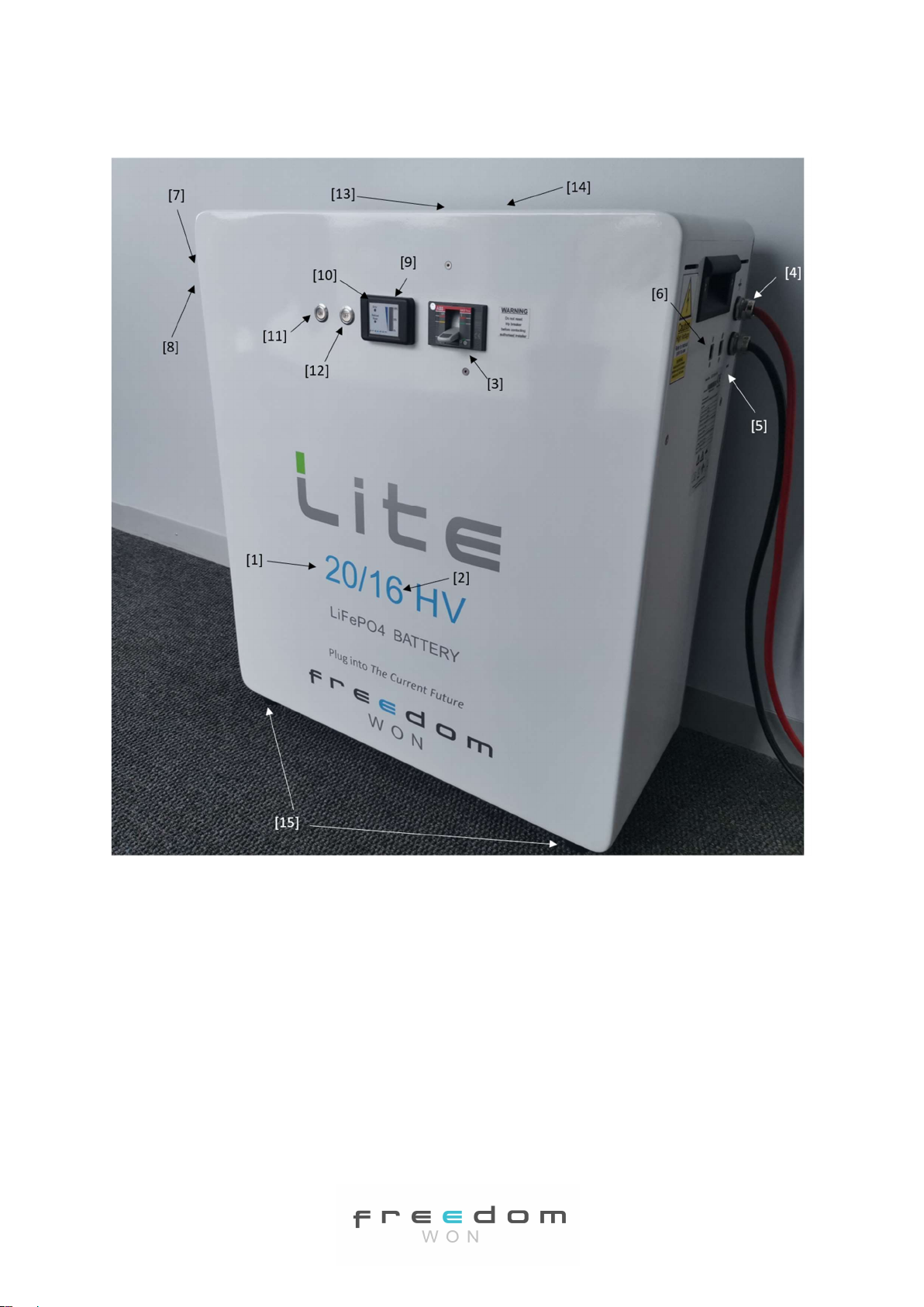
The Lite range includes an integrated battery DC breaker/isolator that breaks the positive
cable continuity inside the battery. This breaker, on all Home and Business models, is rated
for a 36kA fault (short circuit) current. The system therefore does not require another DC
isolator or breaker except where required in relation to conformance with the Clean Energy
Council of Australia battery design Best Practice Guide, which states that, should the
internal battery isolator not offer isolation of BOTH the positive and negative terminals of
the battery, an external isolator is required that can isolate both the positive and negative
cables/terminals of the battery.
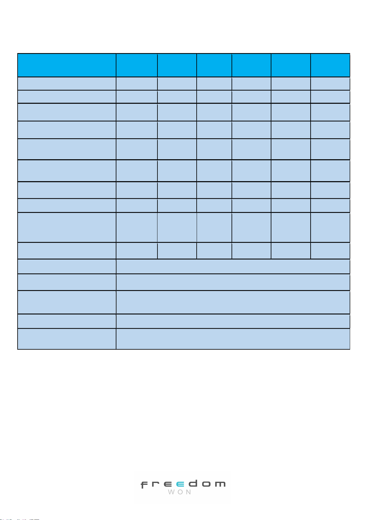
The approximate short circuit current values of each battery model are provided in the table
below:
Table 3.1 Short Circuit Current for Lite Home and Business Models
Freedom Lite Home
15/12HV
Home
20/16HV
Home
30/24HV
[30/24HV+]
Business
40/32HV
[40/32HV+]
Business
60/48HV
[60/48HV+]
Business
80/64HV
Short Circuit Current [A] 3100 3600 4700 5100 5800 6200
The external isolating device required for installations in Australia should be designed to
withstand these fault levels (short circuit currents).
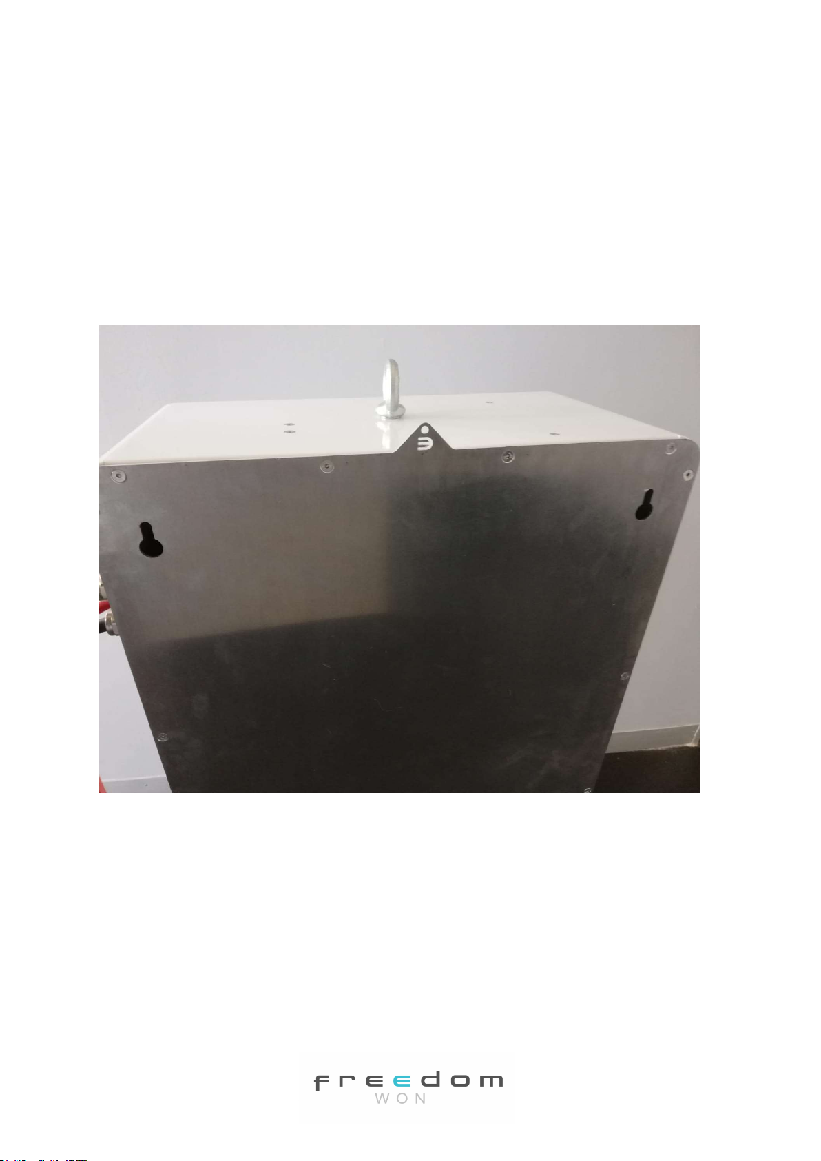
4. Transport, Handling and Mounting
The Freedom Lite units are packaged in protective layering and fastened into a wooden
crate with pallet type feet, which allow lifting with a forklift or a pallet jack. The 15/11HV
and 20/14HV models may be manually handled by four people but are best handled by a
pallet jack or forklift if available. The 30/21HV, 40/28HV, 60/42HV and 80/56HV models
must be handled with care by a forklift or pallet jack of the required lifting capacity rating.
If it is necessary to transport the larger units (typically 40/28 and larger) up or down
multiple stairs in order to get them to the point of installation in the premises it may be
preferable to deliver the unit with the lithium cells separate and then Freedom Won will fit
them into the unit on site. This must be arranged with Freedom Won at the time of order
placement and will attract a nominal fee for labour plus transport and accommodation
where applicable. This service is not available in all countries. Please enquire with Freedom
Won Sales.
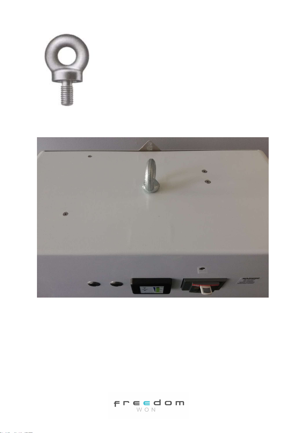
The “Home” series is designed for wall mounting in order to preserve room and floor space
and offer a convenient obstruction free and aesthetically pleasing solution. Each model is
fitted to the wall using two Rawl Bolts. The Rawl Bolts are inserted into correct diameter
pre-drilled holes in the wall. The bolts must first be tightened substantially so that the
internals of the Rawl Bolt have gripped tightly into the wall, and then the bolt must be
turned out slightly with the head protruding so that about 5mm of the bolt shank is

Freedom Lite Home and Business HV Installation Manual Revision 1
P a g e 9 | 25
visible. This pre-tightening prevents the bolt from being pushed into the wall when
mounting the Lite. The Freedom Lite has two keyhole shaped holes on the back, which are
shaped to fit over the bolt heads and then a narrowed section secures around the bolt
shank as the unit is lowered into its final position. The 15/11HV and 20/14HV models are
hung using M8 bolts whilst the 30/21 model is hung on M10 bolts. The larger models are
not equipped with keyholes and must be mounted upright on the floor. The centre to centre
spacing of these bolts must be applicable to the model being installed. It is critical that these
bolts are mounted within 1mm of the correct dimension and must be perfectly level.
Figure 4.1 Bolt Mounting Keyhole on Rear of Lite Casing – floor mount retaining tab and
fitted eye bolt also visible
Eye bolts fixed to the top of the battery can be used for hoisting the unit up to the required
height for fitting to the wall. The eye bolt on the models up to the Lite 20/14 can be
removed after installation. Ensure that you have one M12 x 1,75 thread eye bolt rated for
450kg or more for the models that are not supplied with permanently fixed eye bolts.
Lifting the batteries by the eye bolts should be performed using a mobile gantry crane or a
high lift pallet jack.
Figure 4.2 Eye bolt Example

Freedom Lite Home and Business HV Installation Manual Revision 1
P a g e 10 | 25
Figure 4.3 Eye bolt Installation on a Lite 15/12HV model (remove after installation)
The units can alternatively be lifted to the right height and onto the hanging bolts using a
high-lift pallet jack such as shown in Figure 4.4. A site assembled gantry with electric winch
is shown in Figure 4.5. This gantry is available from Freedom Won as an accessory and is
available with various gantry widths and lifting capacities.
Figure 4.4 High Lift Pallet Jack

Freedom Lite Home and Business HV Installation Manual Revision 1
P a g e 11 | 25
Models up to Lite Home 20/16 are fitted with lifting or manoeuvring handles to make
placement easier. See Fig 5.1.

Freedom Lite Home and Business HV Installation Manual Revision 1
P a g e 12 | 25
Fig 4.5 Site Assembled Gantry with Electric Hoist
Caution:
1. Great care must be taken to ensure that the Rawl Bolt has properly located into the
narrowed section of the mounting hole before removing the support.
2. Handle the Freedom Lite with great care when lifting and manoeuvring. It should
remain either lying flat on its back, on a long side, or vertically upright (it should not
be placed upside down or on its front face. When manoeuvring through a doorway
on its long side be certain to pack spacing foam to prevent damage to the plugs and
glands.
3. Do not allow the pallet jack to over centre if it is a model with forks longer than the
lower arms
4. Take care not to knock any of the protruding items against obstacles during handling
such as the DC cabling and plugs and the circuit breaker handle.
5. Take care not to scratch the Lite during handling. Packaging foam should be used to
protect the paint when being handled on a trolley or pallet jack.
6. Always ensure that lifting equipment and slings are adequately rated for the lifting
weight.
7. Ensure that the eye bolts are fully screwed into the hard point thread on the top of
the unit before lifting.
8. Wear personal protective equipment such as safety shoes and gloves while handling
and mounting the Freedom Lite

Freedom Lite Home and Business HV Installation Manual Revision 1
P a g e 13 | 25
9. Always ensure that you have enough people on hand to perform the operation safely,
i.e. at least one person to guide and stabilise and one person to hoist or handle the
pallet jack or gantry.
10. The gantry can be configured for wall mounting – when using the gantry in this
configuration absolute care must be taken to prevent the gantry from being pulled
over by non-vertical tension on the rope.
Mounting and Environmental Requirements
The Lite Home and Business HV models are designed strictly for indoor use away from
moisture and direct sunlight.
No specific venting is required since the Lite emits no hazardous gases, however air
circulation may be required to ensure room temperature is maintained at reasonable levels,
preferably below 30˚C (see Lite warranty for information upper temperature limits for hot
environments).
Room heating may be required in cold climates to keep the room above 0˚C, since charging
of the Lite is not permitted below 0˚C. Ambient environments that regularly exceeding 40˚C
should employ room cooling if practicable to ensure optimal Lite service life.
Temporary storage or transport of the battery is permitted in the range -20˚C to 45˚C,
however extended storage should be between 0˚C and 30˚C.
The Lite may be mounted directly against a wall or on the floor. There is no minimum
requirement for spacing around the battery from other objects provided that these objects
do not generate heat and that the vents on the sides of the battery are not blocked. Note
however that access is required to the USB programming port on the left side, and the CAN
Bus plug sockets and cable exits on the right side.
The Lite should be installed at least 500mm way from a heat source.
The Lite Home and Business IP rating is IP20.
5. Connecting the Freedom Lite
5.1 Power Cables
The Freedom Lite is simple to connect to the battery inverter. First of all you will connect
the battery positive and negative cables to the inverter terminals using the applicable lugs.
Caution: Prior to connecting the positive and negative cables to the inverter be sure to
check that the main battery circuit breaker is switched off. This will ensure that there are
no short circuits between the loose ends of the cables and that you do not shock yourself!
The cables are supplied with the Freedom Lite, permanently fixed into the unit and secured
onto the casing using compression cable glands. Attach crimp lugs to the ends of both cables
ensuring that the correct terminal size is used, and the lug is matched to the size of the
cable. The positive cable is red, and the negative cable is black. This is confirmed by + and –

Freedom Lite Home and Business HV Installation Manual Revision 1
P a g e 14 | 25
signs on the battery casing beside the respective cables. See Tables 2.1 for the cable size
and quantity fitted to each Freedom Lite HV model. The cable cross sectional area is based
on an acceptable voltage drop with the inverter being mounted on the wall adjacent to the
Freedom Lite battery so that the cable run is less than 5m (note however that the standard
cable length is 1,8m, longer cables available on request).
Cable runs longer than 5m should be assessed and larger cables considered for extending
the Freedom Lite cables to minimise voltage drop. Double Insulation welding cable is
recommended, rated for at least 600V.
The cables may be routed through trunking and connected into the inverter on the positive
and negative terminals, respectively. On Installations where there is more than one inverter
a DC connector box is required as a common point to route the DC cables to each inverter
so that the DC cable run can be kept the same length to all inverters.
5.2 Control Cables – Overview
For controlling external devices, you will need to connect the CAN Bus cable that allows the
Battery Management System inside the Freedom Lite to control, and interface with, these
devices.
The CAN Bus connection is made using the RJ45 plug with the pin configuration on the
battery plug end provided in Table 5.1.
Table 5.1 Colour Coding and Pin Configuration for CAN Bus UTP Control Cable
RJ45 Pin No. Standard Ethernet Cable Colours Wire Function
Pin 7 Brown/White CAN High
Pin 8 Brown CAN Low
Only Victron is accommodated by the pin populations in Table 5.1 using a standard Type T-
568B RJ45 terminated UTP cable. For other inverter brands, please refer to the respective
inverter brands’ manuals for their pin configuration or contact Freedom Won for assistance.
Some brands are covered in Table 5.2 below.
Special CAN cables for supported inverter brands are available from Freedom Won (see
accessories section). Please ensure that you use a correctly configured cable to prevent
damage to any CAN Bus devices.
5.3 CAN Bus Control – Detailed Description
CAN is a widely used communication protocol in systems with many devices that must
report their status or send commands to other devices on the same network. The Freedom
Lite BMS can transmit messages and commands in CAN protocol to provide information to,
but more importantly to control, external devices. CAN allows great versatility and provides
a simple installation because there are only two wires required in this form of
communication, namely CAN High and CAN Low. In order for an inverter or charge

Freedom Lite Home and Business HV Installation Manual Revision 1
P a g e 15 | 25
controller to be controlled by CAN it must first of all be equipped with a CAN interface as
well as a suitable method of connecting the CAN wires. Further to this the Freedom Lite
BMS must be programmed with a CAN messaging profile that is developed for the inverter
or charge controller being used. This profile must be specifically developed for each inverter
model or model range. To date Freedom Won has developed CAN profiles for the following
high DC voltage inverter equipment in relation to the Home and Business HV and HV+ range:
Ingeteam Sun Storage Battery Inverters
ATESS (HPS and PCS ranges)
Solax
Goodwe
Socomec
Sofar Solar
Solis
Elpower
Vensys
ABB
Freedom Won welcomes any requests to produce and test BMS CAN profiles for other
inverters that are CAN equipped for BMS interfacing. For a list of approved CAN interfaces
for 48V inverters please refer to the Home and Business 52V manual.
The CAN interface can provide the following functionality to compatible devices:
i. Charge Current Limit of all Lite’s connected
ii. Discharge Current Limit of all Lite’s connected
iii. Actual State of Charge (minimum of all lights connected)
iv. Actual Battery Temperature (highest of all lights connected)
v. Actual Voltage
vi. Actual Current (total of all Lite’s connected)
vii. Maximum real time charge voltage setpoint
viii. Battery Name
ix. Highest Cell Voltage of all Lite’s connected
x. Lowest Cell Voltage of all Lite’s connected.
xi. Firmware Version
xii. Ah capacity of all batteries connected
xiii. Advanced communication between all connected Lites
The CAN 2.0 Part A and Part B standard uses the SAE J1939 standard in the Lite. It is
necessary to install a 120 Ohm resistor on each extreme end of the CAN cable (splices do
not require a resistor). Most devices operating on CAN have two plugs to connect an
incoming cable in and then outgoing cable on the CAN Bus. The first and the last device in
the chain must have a termination resistor plugged into the spare (second) plug. These
resistor plugs are available from Freedom Won (if you are using Victron then you can use

Freedom Lite Home and Business HV Installation Manual Revision 1
P a g e 16 | 25
the Victron supplied resistors). SMA, Imeon, Solax and Victron operate on this basis for
example. Ingeteam has a separate CAN terminal block for bare wires to be inserted from the
BMS and these units have an internal resistor fitted into the device. All Freedom Lite models
have two CAN plugs for parallel configurations (Figure 4.2) and to allow fitment of the
termination resistors on the end of line units. Where one Lite is installed or where it is the
end of line CAN device, the Lite must be fitted with a termination resistor.
The Lite is supplied with a termination resistor as standard. The other devices must be fitted
with the correct termination resistor for that particular brand, where applicable (some
devices have a built-in resistor). Note that the resistor supplied by Freedom Won must only
be used on the battery.
The third-party device manuals must be referenced for all details regarding connecting the
CAN interface.
The Lite profile is in most cases specifically designed for a particular inverter from the above
list. The inverter pairing should be stated when ordering a HV or HV+ battery so that the
battery can be shipped with the correct profile. If this is not done the profile can easily be
changed during commissioning by your distributor for Freedom Won technical support.
Fig 4.1 provides the standard colour coding for an Ethernet cable (note that there are other
variations so double check this).
Fig 5.1 Pin Configuration of Type T-568B RJ45 Plug
Table 5.2 Pin Configuration for CAN Bus Control Cable for various supported inverters
Wire
Function
Standard
Lite and
Victron
SMA Ingeteam Imeon,
Sofar
Solar
Solax Goodwe,
Solis,
Sunsynk
CAN
Low
Pin 8
(brown)
Pin 5 (blue/
white)
Labelled
on inverter
Pin 2
(orange)
Pin 1
(orange/
white)
Pin 5
(blue/
white)
CAN
High
Pin 7
(brown/
white)
Pin 4 (blue) Pin 1
(orange/
white)
Pin 2
(orange)
Pin 4
(blue)
.
Bridge Pin 3 and
Pin 6 on Inverter
end of cable with
a 120Ω resistor

Freedom Lite Home and Business HV Installation Manual Revision 1
P a g e 17 | 25
If your inverter is not included in this table or you require more information on how to
connect the CAN Bus on your inverter, please contact Freedom Won for assistance.
5.4 Parallel Configurations
It is permissible to connect multiple Freedom Lite’s in parallel provided that the Freedom
Lite model size used is the same throughout. It is however more cost effective to purchase
one larger Freedom Lite model than connecting multiple units in parallel. This type of
installation should be reserved for future expansion where it is not feasible to purchase a
model large enough upfront for future requirements (financial constraints).
The Lite operating system will automatically configure which battery is the master and
which ones are slaves (the first battery to be switched on in a parallel setup will be the
master). The Lite is therefore plug and play capable, there is no configuration required
during commissioning.
The Master Lite must be connected to the slave Lite’s via the CAN Bus using standard LAN
cable.
Where CAN Bus is used to control the inverter(s) and charge controller(s), the CAN Bus from
any battery can be connected to the inverter directly or the system controller, depending on
the product brand.
Figure 4.2 Picture Showing 2 x RJ45 Sockets for CAN Bus, the DC cables, High Voltage
warning label, Model specifications Label and Manoeuvring Handle

Freedom Lite Home and Business HV Installation Manual Revision 1
P a g e 18 | 25

Freedom Lite Home and Business HV Installation Manual Revision 1
P a g e 19 | 25
Figure 4.2 CAN Bus Connection Example with Three Lite HV’s – the inverter includes the CAN
Bus connection; in some brands the CAN may connect to a separate controller.
In Fig 4.2 the inverter may include a built-in resistor with a dip switch to enable it or it may
provide a second plug to accept a RJ45 termination resistor. Some inverters have screw
terminals to accept a bare wire instead of a plug.
Freedom Lite batteries can configure themselves automatically for master and slave
configurations with up to 20 slaves. No programming is required, simply connect the CAN
Bus cables and switch on the Lite’s. The Master will be the first battery that was switched
on.
If the master Lite trips, one of the slaves will take over as the master automatically without
any interruption of service.
Freedom Won offers a fair trade in on Freedom Lite’s on the purchase of new units, which is
an option for somebody wishing to expand their battery capacity instead of installing
parallel units. Please request more detail from Freedom Won if this is your upgrade
preference.
New units can be placed in parallel with old units up to about 5 years or 1 500 cycles, after
which it is preferable to trade in for a new larger unit.
6. Programming the Freedom Lite
The USB plug on the left-hand side of the Freedom Lite is used for setting up the profile of
the BMS. The computer must have the correct utility software installed. Programming of the
BMS is intended only as a function to be performed by Freedom Won and approved
installers. The manual on how to operate the BMS along with the utility is available to
approved installers from Freedom Won. Write access to the BMS profile is password
protected, however users and owners may request read only access.

Freedom Lite Home and Business HV Installation Manual Revision 1
P a g e 20 | 25
7. Switching on the Lite
The Lite is fitted with an “ON” button. Press this button for at least 5 seconds to switch on
the BMS inside the battery. Once the BMS has been energised you will observe the SoC
display come to life with the SoC level shown. Confirm at this stage that the error lite is not
illuminated. If it is, contact Freedom Won. If the Reduced Power light is illuminated, do not
be concerned, it should extinguish after the battery has been in operation for a few hours.
Once the BMS has been energised, the main breaker may be switched on by pushing the
breaker upwards. Ensure beforehand that you have secured the DC cables to their proper
locations and that the rest of the system is ready to receive battery voltage.
CAUTION: The batteries in this range operate at potentially lethal voltages, the installer
must make certain that there is no risk of electric shock before switching on the battery!
Note: On some inverters there is a large inrush current when switching on the DC supply. It
is important in these instances to pre charge the DC bus. Other inverters are equipped with
a pre-charge circuit – check before you switch on the battery to avoid damaging the battery
breaker.
To switch off the DC output from the Lite, pull down the breaker. To switch off the power to
the BMS, press the “OFF” button situated to the right of the “ON” button. This will also trip
the breaker if it is still on at the time. The Lite must be switched off fully when not in use to
prevent self-discharge.
Fig 7.1 “ON” and “OFF” Buttons
8. Settings Required for Setting up Inverters and Charge
Controllers
The maximum and continuous discharge and charge currents for the respective models are
provided in Table 2.1. The inverter should be configured within these limits. Generally the
CAN bus messages from the battery will determine these limits.
This manual suits for next models
5
Table of contents
Other Freedom Won Camera Accessories manuals

Freedom Won
Freedom Won Lite Commercial Series User manual

Freedom Won
Freedom Won Lite Home 5/4 User manual

Freedom Won
Freedom Won LiTE Home 10/8 User manual

Freedom Won
Freedom Won Lite Home 5/4 User manual

Freedom Won
Freedom Won Lite Commercial Series User manual

Freedom Won
Freedom Won eTower User manual
Popular Camera Accessories manuals by other brands

AVIRE
AVIRE MRL DCP installation guide

Filmcity
Filmcity FC-A7RS-Kit instruction manual

PASCO
PASCO PS-3203 Replacement instructions

urmet domus
urmet domus 1092 user manual

Orange Micro
Orange Micro RAMPAK 4GS Operator's manual

Photogenic Professional Lighting
Photogenic Professional Lighting PowerLight 1250 Operator's manual