Freedom Won Lite Commercial Series User manual

Installation and User Manual
Freedom Lite Commercial
52V and HV Models
Lithium Iron Phosphate Batteries
Manufactured By Freedom Won (Pty) Ltd
Unit 23
Ruimsig Shopping Centre
Muriel Road
Amorosa
Gauteng Province
1732
South Africa
www.freedomwon.co.za
Technical and Installation Assistance – Contact:
Please contact your Freedom Won Distributor or Reseller Installer for technical and installation
support. A directory of Distributors and Reseller Installers is available at www.freedomwon.co.za.
For advanced support please contact [email protected].
Revision 1 – 18 August 2019

Freedom Lite Installation Manual Revision 10
1. Introduction
This manual is intended to provide assistance to an installer for the installation and
commissioning – and to the user for the operation of – the range of Freedom Lite
Commercial lithium iron phosphate (LiFePO4) energy storage modules manufactured by
Freedom Won. This document is not intended to provide detailed information of the inner
workings of the Freedom Lite beyond the scope of installation, commissioning and the
ongoing use of the product.
Supplementary information relating to programming of the built-in battery management
system for specific applications is available to approved integrators directly from Freedom
Won.
This manual does not attempt to cover all the details pertaining to the setup of third-party
equipment in relation to the interface and necessary functionality to work with the Lite.
Freedom Won however is available at the contact details on page one to provide direct
support where necessary for supported third party brands.
2. Product Description
The Freedom Lite technology is available in various standard sizes to meet all residential,
commercial and industrial applications ranging from 5kWh up to 2500kWh. Even larger
systems are provided by Freedom Won based on specific project requirements by installing
multiple units in parallel.
Freedom Won offers the following ranges in the LiFePO4 technology:
1. Lite 12V
2. Lite Mini (note this range is only available for volume orders in specific countries,
please enquire with Freedom Won Sales)
3. Lite Home and Business
4. Lite HV Home and Business
5. Lite Marine
6. Lite Mobility (golf carts, forklifts etc)
7. Lite Commercial
8. Lite Industrial
This manual covers the Lite Commercial range from 100kWh up to 700kWh. For information
specific to the other ranges please refer to the applicable manuals. The Lite Commercial
range offers world leading levels of power output for the respective battery capacity with a
an extremely robust and advanced system architecture. Furthermore the cost vs
performance of this range is world leading.
The complete Lite Commercial range is available in a voltage of 52V nominal (to suit 48V
systems). The Freedom Lite Commercial range is also available in higher voltages to suit
specific high DC voltage inverters and is referred to generally as the Lite Commercial HV
Page 1 | 28

Freedom Lite Installation Manual Revision 10
range. The Lite Commercial HV range is available in various nominal DC operating voltages
up to 800V depending on customer requirements.
Table 2.1 provides an overview of the 52V Freedom Lite Commercial range. There are ten
Freedom Lite models in the 52V Commercial range, as included in the table, classified in
terms of energy capacity.
The Commercial HV range is predominantly provided in the voltage option to suit the most
common inverter pairing i.e. 512V DC for the Growatt ATESS industrial inverters. Up to 800V
DC nominal for the Ingeteam 1MW class battery inverters and other similar battery
inverters is also available. Refer to Table 2.2 for the HV model options to suit the Growatt
inverters. Please contact Freedom Won should specific technical information be required for
the models suited to the Ingeteam 1MW class battery inverters and any other brand of high
DC voltage battery inverter.
An image with numbered labels pertaining to the following paragraphs is provided in Figure
2.1. The model number denotes with the first number [1] the total energy storage capacity
in kWh of each model. The second number [2] denotes the average amount of energy in
kWh that should be withdrawn per cycle (on average) in order to optimise the life of the
lithium cells. This equates to 70% of the total for each model i.e. 70% depth of discharge
(DoD). Note that all Freedom Lite batteries offer a maximum of 90% DoD as standard.
The range is designed with a tall and slim profile for standing on the floor against a wall to
ensure a minimal floor area requirement. Aluminium feet with plastic pads on the underside
are fitted as standard. There are also anchor points for bolting the battery to the wall where
required eg. when installed into a container prior to transporting to site.
The Ah capacity is provided in the tables for each model for easy reference.
The maximum current for each model is governed by the rating of the built-in circuit breaker
[3], which has been sized well below the maximum current capability of the lithium cells. For
this reason, there is no noticeable temperature rise during operation and no cooling of the
cells is required. There is no specific time limit for operation at the maximum current,
however, to ensure that the circuit breaker does not trip in normal operation, it is advised
that the design of the system aims to remain at or below the continuous current value.
Page 2 | 28

Freedom Lite Installation Manual Revision 10
Figure 2.1 Labelled Image of the Freedom Lite Commercial 100/70 (Labelling corresponds
with the text)
1. Gross Capacity
2. 70% Capacity recommended for daily cycling (max available is 90%)
3. Breaker
4. Power Cables
5. DB15 Analogue and Relay Control Port (optional)
Page 3 | 28

Freedom Lite Installation Manual Revision 10
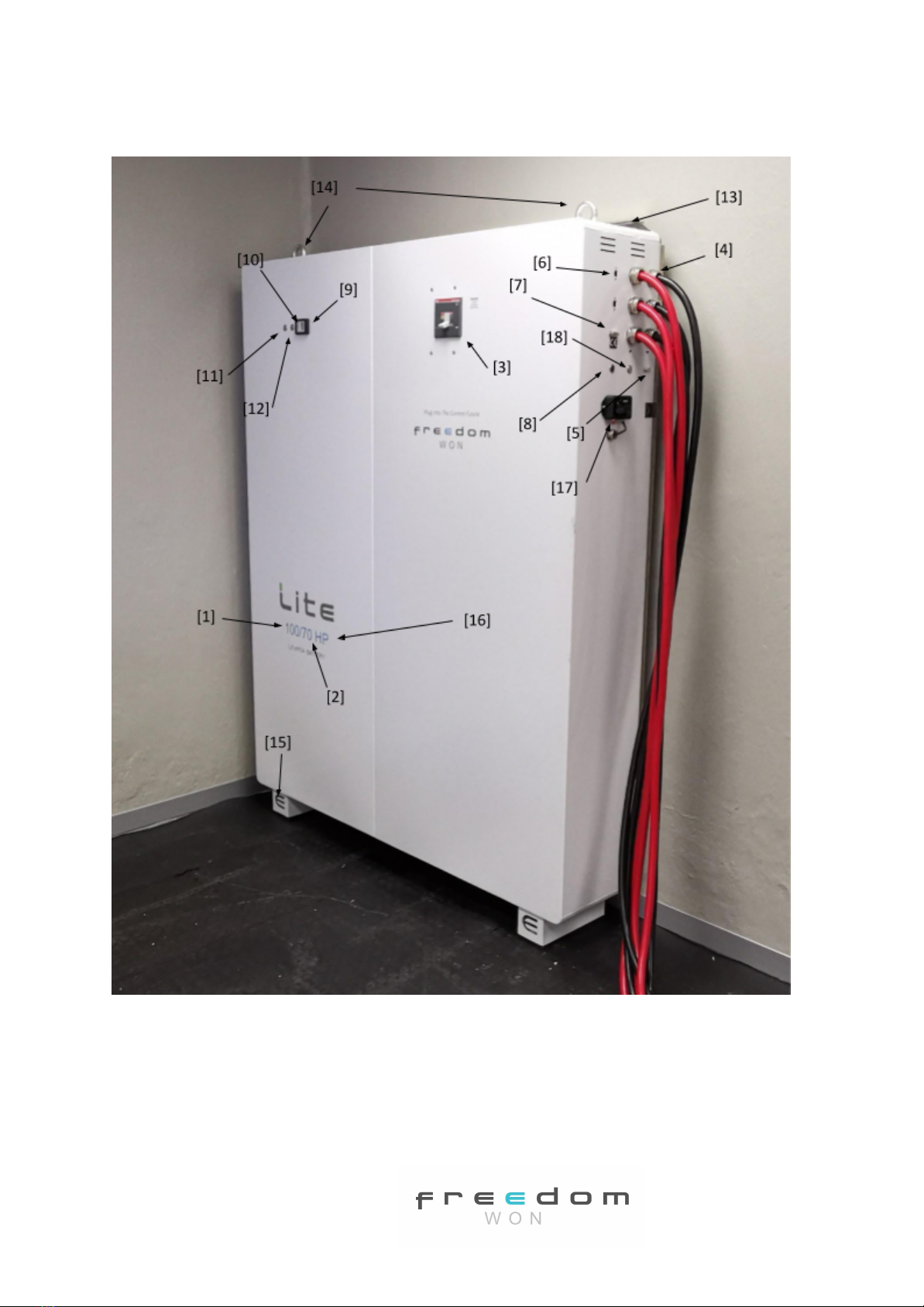
6. CAN Bus Sockets x 2 (RJ45) (one socket must contain a termination resistor if end of
line)
7. DB9 Programming Port (not visible in photo)
8. Reset Button
9. State of Charge Display
10. Error Lite
11. On Button
12. Off Button
13. Safety Retaining Tabs
14. Lifting Eye Bolts
15. Feet
16. Power Level Designator (absent for standard model) – note, the HP models have
become the new standard models as of 1 April 2019 and the HP upgrade is no longer
available
17. WiFi Connect Data Logging and Reporting
18. Override Button
For the 52V models the absolute maximum allowable voltage when fully charged is 56V,
however a more typical inverter setting range is 55.5V to 55.8V, depending on the inverter
voltage tracking accuracy in preventing a voltage overshoot above 56V. The voltage
normally used as the minimum cut off is 48V, however this will not typically be reached if
operating down to 90% Depth of Discharge (DoD). The BMS will command the connected
inverter with CAN Bus interface to stop discharging the battery at 10% SoC (90% DoD),
which roughly equates to 49,0V). Under high load the voltage may drop to 48V whilst still
above 10% SoC. A voltage of 48V or even lower can be observed where the standby current
draw on the inverter has caused the battery to be discharged below 10% SoC or below the
48V minimum cut off voltage. The battery breaker will eventually trip the battery at around
47V to protect the cells from undervoltage.
The Commercial HV models operate at 512V for most models as this is the ideal operating
voltage for the ATESS battery inverters (a common pairing). There are three models with
different voltages because of the differing cell architecture required to build these models –
refer to specification sheet for more details.
The weight of each model is given in the tables 2.1 and 2.2. The Freedom Lite Commercial
100/70, 120/84 and 140/98 are assembled complete in the Freedom Won factory as
standard. The 160/112 up to the largest 700/490 are either assembled on site by a Freedom
Won site team or, if preferred by the client, can be built into a container at Freedom Won
by the Freedom Won factory team.
The 100/70, 120/84 and 140/98 models require specific lifting equipment to place them into
position. Should a specific site present logistical constraints in relation to placing these
models into position, it is possible to request that Freedom Won assemble the batteries on
site at an additional cost.
Page 4 | 28

Freedom Lite Installation Manual Revision 10
The dimensions given in the specification sheets are for the principle outlines of the battery
housing and exclude items that protrude such as the DC cable glands and the circuit breaker
handle.
The DC cables exit the unit through glands located near the top of the right hand side of the
casing (as in Fig 2.1) for the 100/70 and 120/84 models, and near the right side of the top of
the casing for the rest of the range (as in Figure 2.2).
Fig 2.2 Top Cable Exit Example on a Lite Commercial 200/140
The DC cables per pole vary in number and size across these models [3 in Figure 2.1 for
example]. The correct cable lugs for connecting these leads to the inverter must be in hand
when doing an installation. If there are several inverters and charge controllers that need to
be connected to the battery it is advisable to install a DC connector box to use as a junction
Page 5 | 28

Freedom Lite Installation Manual Revision 10
point from which to branch out to all the battery connected equipment. Note that the
cables are provided 3m long as standard and up to 5m long can be ordered at extra cost.
An optional DB15 plug [5 in Figure 2.1] is located below the DC fly lead glands for connection
in installations where an analogue or dry contact interface compatible inverter or charge
controller is used.
Two RJ45 sockets [6] are provided, one for connecting the CAN interface from the battery to
the system controller or directly to the inverter depending on the brand, and another for
connecting the battery to another battery or for a termination resistor (more detail later in
manual).
A DB9 Serial Connector [7] is fitted for use by technicians for programming the required
profile onto the BMS. The required profile is typically loaded by Freedom Won prior to
delivery or during commissioning for site build models but installers are advised to obtain
the correct adapter to allow Freedom Won to program batteries remotely on behalf of the
installer via the installer’s Windows laptop if necessary. Note the correct adapter for the Lite
Commercial range is a CANdapter (Figure 2.2). This is available from Freedom Won as an
accessory; however all batteries are supplied with one CANdapter as standard.
An error reset button [8] is positioned near the DB9 plug for clearing BMS errors.
Freedom Lite is also fitted with a State of Charge (SoC) display [9], which includes a red LED
error indicator [10] and below it a “low power” indicator.
The ON button [11] and OFF button [12] are located beside the SoC display.
The Lite is supplied with securing tabs along the top and bottom as part of the rear cover to
secure the battery against the wall to prevent it from tipping over [13] or shifting if installed
into a container to be transported to site.
All Lite’s have feet as standard, with plastic slippers underneath [15].
All models are supplied with permanently installed eye bolts. For the 100/70, 120/84, and
140/98, these eye bolts are provided for lifting the full battery mass. For the larger models
(160/112 and larger) these eyebolts are provided for lifting the empty casing only (prior to
battery assembly). Do not attempt to lift these models using the eye bolts after assembly is
completed.
Page 6 | 28

Freedom Lite Installation Manual Revision 10
Table 2.1 Freedom Lite Commercial 52V Range Overview
Freedom Lite
Commercial
100/70
120/84
140/98
160/112
200/140
300/210
400/280
500/350
600/420
700/490
Total Energy Capacity
[kWh]
100
120
140
160
200
300
400
500
600
700
70% DoD Energy [kWh]
70
84
98
112
140
210
280
350
420
490
90% DoD Energy [kWh]
90
108
126
144
180
270
360
450
540
630
Current Capacity [Ah]
2 000
2 400
2 800
3 200
4 000
6 000
8 000
10 000
12 000
14 000
Max. Cont. Charge and
Discharge Current (1)
[A]
2 000
2 000
2 400
2 400
2 400
2 800
2 800
2 800
2 800
2 800
Max. Cont. Charge &
Discharge Power (1)
[kW]
100
100
120
120
120
140
140
140
140
140
Nominal Voltage (2) [V]
52
Max. Inverter Cap.
[kVA]
90
90
108
108
108
135
135
135
135
135
Total Weight [kg]
1 040
1 250
1 500
1 700
2 200
3 300
4 300
5 300
6 300
7 400
Height [mm]
2 100
Depth (from wall) [mm]
350
750
Length (width along
wall) [mm]
1 400
1 850
2 300
2 750
3 200
4 600
3 200
4 100
4 600
5 500
DC Connection – Fly
Leads, [no. per
electrode] (3) [mm2]
3x120
3x120
4x120
4x120
4x120
6x120
6x120
6x120
6x120
6x120
Round Trip Efficiency
96-97%
Enclosure
3mm thick Aluminium, powder coated, tamper proof, indoor use
External Interface (4)
CAN Bus
On-board Management
Full battery management system and internal trip protection
Human Interfaces
On and Off Buttons, State of Charge Display (0 to 100%), Error light, Error Reset Button, CANdapter for
Programming and data access with PC, main breaker
Protection
Shunt Trip Circuit Breaker sized to suit max current, can be tripped by BMS if critical fault, manual reset.
Protection for overcurrent, cell under and over voltage, temperature, weak cell detection and other critical
events
Battery Chemistry
Lithium Iron Phosphate (LiFePO4)
Cell Form Factor
Large Format ultra-heavy-duty prismatic cells of 200Ah each and 3,2V nominal voltage, fully sealed in plastic
casing with bolt on electrode connections
Battery Cooling
Natural Convection (heat generation is negligible inside the battery)
Suitable Ambient Temp
[°C]
0°C to +40°C
Extreme Operating
Temp [°C] (5)
-20°C to +60°C
Remote Monitoring
Real time data logging and transmission via WiFi to online portal of key battery information
Warranty (6)
10 years or 4 000 cycles for average 80% DoD, and max 90% DoD
Design Life
>16 years (>6 000 cycles) expected life at 70% DoD per cycle, >20 years (>7 500 cycles) at 50% DoD
Notes to Specification Sheet:
1. The maximum (peak) and continuous current and power ratings are the same for the Lite Commercial battery
range. The maximum values given apply to both charge and discharge. For systems requiring more than 140kW,
two or more batteries must be installed in parallel.
2. Higher voltage batteries are available on request ranging up to 750V DC (nominal).
Page 7 | 28

Freedom Lite Installation Manual Revision 10
3. Fly Leads 3.0m long as standard, power cable Red = Positive, Black = Negative, conductors in table refer to one
electrode i.e. per positive and negative connections. Up to 5m long available at extra cost (must be specified in
order). Note that the fly leads exit the battery as follows according to the model:
●Model 100/70 and 120/84 – Exit is on the right-hand side of the battery enclosure near the top
●Other models – Exit is on the top of the battery near the right-hand side
4. Potential free contacts and analogue outputs also available on request for several control features (details on
request).
5. Charging below 0°C not permitted. Extended time above 45°C not recommended for optimal battery life.
6. See Freedom Won Warranty document for further detail.
Page 8 | 28

Freedom Lite Installation Manual Revision 10
Table 2.2 Freedom Lite Commercial HV Range Overview (to suit Growatt ATESS and similar
inverters)
Freedom Lite
Commercial
100/70
120/84
140/98
*
160/112
†
200/140
300/210
400/280
500/350
600/420
700/490
Total Energy Capacity
[kWh]
100
120
140
160
200
300
400
500
600
700
70% DoD Energy [kWh]
70
84
98
112
140
210
280
350
420
490
90% DoD Energy [kWh]
90
108
126
144
180
270
360
450
540
630
Current Capacity [Ah]
200
200
200
400
(200)
400
600
800
1 000
1 200
1 400
Max. Cont. Charge and
Discharge Current (1)
[A]
220
200
200
280
(200)
400
600
800
800
800
800
Max. Cont. Charge &
Discharge Power (1)
[kW]
112
120
143
115
200
300
400
400
400
400
Nominal Voltage (2) [V]
512
602
717
410
(820)
512
512
512
512
512
512
Max. Inverter Cap.
[kVA]
120
120
140
120
(160)
200
300
400
400
400
400
Total Weight [kg]
1 040
1 250
1 500
1 700
2 200
3 300
4 300
5 300
6 300
7 400
Height [mm]
2 100
Depth (from wall) [mm]
350
750
Length (width along
wall) [mm]
1 400
1 850
2 300
2 750
3 200
4 600
3 200
4 100
4 600
5 500
DC Connection – Fly
Leads, [no. per
electrode] (3) [mm2]
1x70
1x70
1x70
1x95
1x95
1x120
1x185
1x185
1x185
1x185
Round Trip Efficiency
96-97%
Enclosure
3mm thick Aluminium, powder coated, tamper proof, indoor use
External Interface (4)
CAN Bus
On-board Management
Full battery management system and internal trip protection
Human Interfaces
On and Off Buttons, State of Charge Display (0 to 100%), Error light, Error Reset Button, CANdapter for
Programming and data access with PC, main breaker
Protection
Shunt Trip Circuit Breaker sized to suit max current, can be tripped by BMS if critical fault, manual reset.
Protection for overcurrent, cell under and over voltage, temperature, weak cell detection and other critical
events
Battery Chemistry
Lithium Iron Phosphate (LiFePO4)
Cell Form Factor
Large Format ultra-heavy-duty prismatic cells of 200Ah each and 3,2V nominal voltage, fully sealed in plastic
casing with bolt on electrode connections
Battery Cooling
Natural Convection (heat generation is negligible inside the battery)
Suitable Ambient Temp
[°C]
0°C to +40°C
Extreme Operating
Temp [°C] (5)
-20°C to +60°C
Remote Monitoring
Real time data logging and transmission via WiFi to online portal of key battery information
Warranty (6)
10 years or 4 000 cycles for average 80% DoD, and max 90% DoD
Design Life – Cycles
>16 years (>6 000 cycles) expected life at 70% DoD per cycle, >20 years (>7 500 cycles) at 50% DoD
Page 9 | 28

Freedom Lite Installation Manual Revision 10
Notes to Specification Sheet:
* The Lite Commercial 140/98 is not suitable for the ATESS HPS range (the voltage is too high) but it is suitable
for the full PCS range .
†The Lite Commercial 160/112 can be supplied in two voltage options – 410V or 820V. The 410V option is
required for the ATESS HPS range of inverters. The 820V option is required for the ATESS PCS500 and PCS630
models. This model cannot be used with the PCS models PCS250 and below.
1. The maximum (peak) and continuous current and power ratings are the same for the Lite Commercial HV battery
range. The maximum values given apply to both charge and discharge. For systems requiring more than 400kW,
two or more batteries must be installed in parallel. For example, if a ATESS PCS500 battery inverter is required,
the battery system can comprise of 2 x Lite Commercial 300/210 models in parallel.
2. Higher voltage custom batteries are available on request ranging up to 750V DC (nominal) should this be required
for other types of inverters. Note that custom voltages will result in different battery capacities from what is
included in this specification sheet – please contact Freedom Won for further details.
3. Fly Leads 3.0m long as standard, power cable Red = Positive, Black = Negative, conductors in table refer to one
electrode i.e. per positive and negative connections. Up to 5m long available at extra cost (must be specified in
order). Note that the fly lead exit the battery on the right hand side near the floor on all the Lite Commercial HV
models. This is to suit the bottom entry of the floor standing ATESS inverters. A cable trench is recommended for
routing this cable along with all the other cables going to and from the inverter.
4. Potential free contacts and analogue outputs also available on request for several control features (details on
request).
5. Charging below 0°C not permitted. Extended time above 45°C not recommended for optimal battery life.
6. See Freedom Won Warranty document for further detail.
Figure 2.3 CANdapter for Programming Freedom Lite Commercial Range
Page 10 | 28

Freedom Lite Installation Manual Revision 10
3. Transport, Handling, Final Positioning and Plant Room Design
The Freedom Lite units are packaged in protective foam layering and fastened into a
wooden crate with feet, which allows lifting with a forklift or a pallet jack.
For the 100/70, 120/84 and 140/98 models the battery is transported complete in a single
crate of outside dimensions 150mm longer, wider and higher than the respective battery
dimensions provided in the specification sheet.
For the 160/112, 200/140 and 300/210 the battery casing is shipped as one piece in one
crate, also with outside dimensions 150mm longer, wider and higher than the respective
dimensions given in the specification sheet. These casings are however not populated with
the lithium cells for shipping, which are shipped in separate crates of a size (587mm x
325mm x 350mm high) and weight (72kg) that can be lifted by two men if necessary. These
crates can also easily be handled with a pallet trolley or forklift.
For models 400/280 up to 700/490 the enclosures are populated with slide in modules
complete with cells. These modules are installed on site and hence the enclosures are
shipped empty. The 700/490 enclosure is shipped in two halves (each 2 750mm long) and
the other models are shipped in one part (see specification sheet for dimensions).
The modules are packaged in individual crates, with each battery comprising of 16 modules.
The modules vary in size and weight depending on the model. The weight of each module
ranges from 240kg on the 400/280 to 420kg on the 700/490. A forklift or hi up crane truck is
therefore required for offloading and a pallet trolley for ground handling. Freedom Won
supplies a portable lifting device for installing the modules into the enclosure during the
installation phase.
For a complete packing list of each model please enquire with Freedom Won.
The models shipped to site complete may be lifted using the fitted eye bolts. The models
shipped unassembled also have eye bolts fitted to the enclosure, which may be used only
for lifting the EMPTY enclosure into position. These eye bolts MUST NOT be used for lifting
the completely assembled battery.
Note that the door to the plant room must be sized adequately in width and height for entry
of the casing. A minimum door opening of 2,3m high x 1,6m wide is recommended. A
minimum roof or ceiling height of 2,4m is recommended to accommodate the top exit
power cables and related cable tray design.
The floor of the plant room should be level power floated concrete, preferably painted with
a floor epoxy.
Manoeuvring area inside the plant room must be adequate for positioning the casing
through the door into the final position.
There must also be sufficient space around the battery to meet the assembly space
requirements for the models that are assembled on site:
Page 11 | 28

Freedom Lite Installation Manual Revision 10
1. The models 160/112, 200/140 and 300/210 are assembled from the rear of the
casing by removing the rear cover, fitting the cells, and replacing the cover. At least
700mm of clearance is required behind the battery for the assembly process. Once
the rear cover has been fitted the battery is moved back against the wall using 2t
pallet trolleys. One pallet trolley is sufficient for the 160/112, and for the 200/140
and 300/210, two such trolleys are required. Note:
the smaller models can also be
positioned inside the plant room using one 2t pallet trolley.
2. The models 400/280 to 700/490 are assembled from the front and therefore the
empty enclosure is first placed in its final position against the wall and then the cell
modules are fitted from the front. A minimum of 750mm space Infront of the
enclosure is ideal for installing the modules. However, in the case of two of these
models being fitted into a shipping container the centre aisle space is limited to
500mm, which can be accommodated.
Fixing holes are provided at the top and bottom of the rear of the enclosures for fixing the
batteries to a wall or container side to prevent movement after installation. These are
specifically required when a battery is installed into a container that will be transported to
site complete with battery and other equipment.
Note: All Lite Commercial models can be offered complete ex-factory installed into a
shipping container. Such systems are pre-commissioned at the Freedom Won factory and
can be combined with the required battery inverters supplied and fitted by Freedom Won.
For lifting the factory assembled Commercial units into position specialised equipment is
required. A high-up truck crane or a forklift is required for offloading. For lifting the battery
upright a crane or forklift can be used if there is sufficient height clearance, otherwise a
mobile gantry crane like the one pictured below should be used. These cranes are available
from Freedom Won in three sizes:
1. Small – for lifting models up to Lite 60/42 (not applicable for Commercial range)
2. Medium – for lifting models up to the Lite 100/70
3. Large – for lifting models up to the Lite 140/98
Page 12 | 28

Freedom Lite Installation Manual Revision 10
Fig 3.5 Site Assembled Gantry with Electric Winch
Caution:
1. Handle the Freedom Lite with great care when lifting and manoeuvring. It should
remain either lying flat on its back, or vertically upright (it must not be placed upside
down or on its front face.
2. If manoeuvring through a doorway too low for upright handling is unavoidable the
battery can be positioned (whilst still inside the crate) on its long side. Special
packaging inside the crate is required for this procedure so Freedom Won must be
notified of this requirement prior to collection.
3. Take care not to knock any of the protruding items against obstacles during handling
such as the DC cabling and plugs and the circuit breaker handle.
Page 13 | 28

Freedom Lite Installation Manual Revision 10
4. Take care not to scratch the Lite during handling. Packaging foam should be used to
protect the paint when being handled on a trolley or pallet jack.
5. Always ensure that lifting equipment and slings are adequately rated for the lifting
weight.
6. Wear personal protective equipment such as safety shoes and gloves while handling
and mounting the Freedom Lite
7. Always ensure that you have enough people on hand to perform the operation safely,
i.e. at least two persons to guide and stabilise and two persons to hoist or handle the
pallet jack(s).
4. Connecting the Freedom Lite
4.1 Power Cables
The Freedom Lite is simple to connect to the battery inverter. First of all you will connect
the positive and negative cables to the inverter terminals or DC busbar if applicable using
the applicable lugs (not supplied).
Danger:
The Commercial HV range operates at potentially lethal voltages and hence the
battery cables and connections must be treated with the utmost of respect – prior to
connecting the positive and negative cables to the inverter be sure to check that the main
battery circuit breaker is
switched off
. This will ensure that there are no short circuits
between the loose ends of the cables and will also avoid electric shock from the battery
during installation.
The cables are supplied with the Freedom Lite, permanently fixed into the unit and secured
onto the casing using compression cable glands. Attach crimp plugs to the ends of the cables
ensuring that the correct terminal size is used, and the lug is matched to the size of the
cable. The positive cable is red, and the negative cable is black. This is confirmed by + and –
signs on the battery casing beside the respective cables. See Tables 2.1 and 2.2 respectively
for the cable size and quantity fitted to each Freedom Lite model. The standard cable length
is based on the inverter standing on the floor or mounted on the wall as applicable adjacent
to the Freedom Lite battery so that the cable run is less than 3m (note that the standard
cable length is 3.0m, longer cables available on request up to 5m). Note the inverter should
always be on the right-hand side of the battery or opposite the battery with overhead cable
routing.
Longer runs should be assessed, and larger cables or busbars considered, for extending the
Freedom Lite DC connection with the objective of minimising voltage variation between the
battery and the other DC connected equipment. Double insulation welding cable is
recommended. In some instances, multiple cable lengths are used instead of using larger
cable to ensure easier routing and bending of cables in trunking.
The cables may be routed through trunking and connected into the inverter on the positive
and negative terminals respectively. The inverter terminals on most inverters can then be
Page 14 | 28

Freedom Lite Installation Manual Revision 10
used for linking up the charge controller(s) to the DC Bus. On Installations where there are
too many inverters and/or charge controllers to connect to the DC bus using the inverter
terminals as a junction point, a DC connector box or enclosed busbar is required. Where
multiple cables per pole are fitted, the cables can be separately routed directly to separate
equipment (inverters and charge controllers) – if this is done the installer must take care to
ensure that any one of the cable pairs will not be overloaded. The cables for each pole are
connected together inside the battery.
4.2 Control Interface
For controlling external devices you will need to connect the control wiring that allows the
Battery Management System inside the Freedom Lite to control and interface with these
devices.
The preferred option available as standard is to use CAN Bus. The CAN Bus connection uses
a CAT5e or CAT6 ethernet cable plugged into an RJ45 plug on the battery. If CAN Bus is not
available it may be necessary to use analogue or relay driver control. Various control
outputs can be supplied via a DB15 plug and harness. An external relay must be installed for
each relay control channel, which will be controlled by the control pins in the DB15 plug.
The Analogue control is via 0-5V signal outputs. Please enquire with Freedom Won about
the options available should it be required.
CAN is a widely used communication protocol in systems with many devices that must
report their status or send commands to other devices on the same network. The Freedom
Lite BMS can transmit messages and commands in CAN protocol to provide information to,
but more importantly to control, external devices. There are only two wires required in this
form of communication, namely CAN High and CAN Low. In order for an inverter or charge
controller to be controlled by CAN it must first of all be equipped with a CAN interface as
well as a suitable method of connecting the CAN wires. Further to this the Freedom Lite
BMS must be programmed with a CAN messaging profile that is developed for the inverter
or charge controller being used. This profile must be specifically developed for each inverter
model or model range.
The CAN Bus connection is made using the RJ45 plug with the pin configuration on the
battery plug end provided in Table 4.1.
Table 4.1 Colour Coding and Pin Configuration for CAN Bus Control Cable
RJ45 Pin No.
Standard Ethernet Cable Colours
Wire Function
Pin 7
Brown/White
CAN High
Pin 8
Brown
CAN Low
There is no ground pin provided on the battery for the CAN Bus.
For Victron systems using the Color Control or Venus the pin configuration is straight
through and therefore a standard ethernet cable can be used. For other inverters such as
Page 15 | 28

Freedom Lite Installation Manual Revision 10
SMA, Goodwe and Imeon this configuration is such that a special cable is required – please
refer to the respective inverter brands manuals for their pin configuration or contact
Freedom Won for assistance. Special cables for all the supported inverter brands are
available from Freedom Won (see accessories section). Some inverters have free terminal
connections that therefore do not require a plug on the inverter end of the CAN Bus cable
eg. ATESS.
If a particular inverter under consideration only has a Modbus control input for the BMS we
recommend as first option considering another inverter that has a CAN Bus input. If this is
not practical, please discuss the project with Freedom Won so that we can consider using a
CAN Bus to MODBUS converter.
To date Freedom Won has developed CAN profiles for the following equipment:
●SMA Sunny Island Battery Inverters
●Ingeteam Sun Storage Battery Inverters
●Victron Multiplus and Quattro Battery Inverters and MPPT Controllers via the Color
Control GX and Venus system controllers
●Studer
●Imeon
●Solax
●Goodwe
●MLT Drives (2019 models onwards)
●Socomec
●Koyoe
●Growatt (HPS and PCS ranges)
●Sunsynk
Freedom Won welcomes any requests to produce BMS CAN profiles for other inverters that
are CAN equipped for BMS interface.
The CAN interface can provide the following functionality to compatible devices:
i. Charge Current Limit
ii. Discharge Current Limit
iii. Actual State of Charge
iv. Actual Temperature
v. Actual Voltage
vi. Actual Current
vii. Maximum real time charge voltage
viii. Minimum real time discharge voltage
ix. Battery Name
The CAN 2.0 Part A and Part B standard uses the SAE J1939 standard in the Lite. It is
necessary to install a 120 Ohm resistor on each extreme end of the CAN cable. Most devices
operating on CAN have two plugs to connect in and then out again on the common CAN Bus.
Page 16 | 28

Freedom Lite Installation Manual Revision 10
The first and the last device in the chain must have a termination resistor plugged into the
spare (second) plug. These resistor plugs are available from the inverter manufacturer and
from Freedom Won. SMA, Imeon, Solax and Victron operate on this basis. ATESS for
example has a separate CAN terminal block for bare wires to be inserted from the BMS and
these units have an internal resistor fitted into the device. From August 2018 all Freedom
Lite models have two CAN plugs for parallel configurations (Figure 4.2) and allowing fitment
of the termination resistors on the end of line units. Where one Lite is installed or where it is
the end of line CAN device, the Lite must be fitted with a termination resistor by plugging a
RJ45 resistor into the second RJ45 socket on the battery.
The resistor fitted to the battery must be the item manufactured by Victron, also available
from Freedom Won. The termination resistor provided by other inverter brands such as
SMA will not work for the battery end termination, only for the inverter end. These resistors
are not supplied as standard with the battery and should be included in the order with
Freedom Won.
For Victron systems the Victron Color Control or Venus is supplied with 2 x termination
resistors. For parallel Lite configurations installed on inverter systems where these resistors
are not supplied, it is necessary to purchase two from Freedom Won.
The third-party device manuals must be referenced for all details regarding connecting the
CAN interface.
Most brands use 500kbps. If 250kbps is required it is available on the Lite with a specific
profile loaded and should be requested in the order. This can however be changed at any
stage by updating the profile using a PC.
4.3 Parallel Configurations
It is permissible to connect multiple Freedom Lite’s in parallel provided that the Freedom
Lite model size used is the same throughout. It is however more cost effective to purchase
one larger Freedom Lite model than connecting multiple units in parallel. This type of
installation should be reserved for future expansion where it is not feasible to purchase a
model large enough upfront for future requirements (financial constraints).
One Lite is programmed as the Master, while the rest of the Lite’s connected to the DC bus
are programmed as Slaves. A total of 10 units can be connected in parallel.
Where CAN Bus is used to control the inverter(s) and charge controller(s), the CAN Bus from
any battery (preferably the Master) can be connected to the inverter directly or the system
controller, depending on the product brand. As of August 2018 all Freedom Lite Home and
Business models are shipped with hardware that enables them to be configured either as
a master or as a slave. This is achieved by providing two RJ45 sockets on the battery – refer
to Figure 4.2. On the master, one socket is used for an end of line (termination) resistor, and
the other socket for connecting to the next item of equipment, whether it be a slave
battery, an inverter, a solar charge controller, or system controller. On a slave, each socket
is used to connect to another item of equipment.
Page 17 | 28

Freedom Lite Installation Manual Revision 10
Figure 4.2 Picture Showing 2 x RJ45 Sockets for CAN Bus and DB15 Plug for Analogue and
Relay Control (the DB15 plug is an optional extra on the Lite Commercial range)
Figure 4.2 CAN Bus Connection Example with Four Lites
All units are normally shipped with a standalone profile on them. Master units will require a
master profile that includes a parameter input for the number of slaves to be connected.
Slave units need specific slave profiles giving them their address in the system. The profiles
will need to be programmed by Freedom Won remotely via a connected PC or can be
pre-configured in the factory if Freedom Won is made aware of which Lites will be used as
masters and slaves prior to dispatch. Lites programmed as slaves in the factory are labelled
“SLAVE” with the slave number (address) for systems with multiple slaves.
Freedom Won offers a fair trade in on Freedom Lite’s on the purchase of new units, which is
an option for somebody wishing to expand their battery capacity instead of installing
parallel units. Please request more detail from Freedom Won if this is your upgrade
preference.
Page 18 | 28

Freedom Lite Installation Manual Revision 10
New units can be placed in parallel with old units up to about 4 years or 1 300 cycles, after
which it is preferable to trade in for a new larger unit.
1. Switching on the Lite
The Lite is fitted with an “ON” button. Press this button to switch on the BMS inside the
battery. Once the BMS has been energised you will observe the SoC display come to life
with the SoC level. Confirm at this stage that the error lite is not illuminated. If it is, contact
Freedom Won. If the Reduced Power light is illuminated, do not be concerned, it should
extinguish after the battery has been in operation for a few hours.
Once the BMS has been energised, the main breaker may be switched on by pushing the
breaker upwards. Ensure beforehand that you have secured the DC cables to their proper
locations and that the rest of the system is ready to receive battery voltage.
Note: On some inverters there is a large inrush current when switching on the DC supply.
This may trip the battery breaker. Should this occur it is necessary to immediately push
down the breaker handle to reset it, and then immediately attempt a second switch on. If
the breaker trips again it is likely because of an error on the BMS and Freedom Won should
be contacted to assist with diagnosing and clearing the error.
To switch off the DC output from the Lite, pull down the breaker. To switch off the power to
the BMS, press the “OFF” button situated to the right of the “ON” button. This will also trip
the breaker if it is still on at the time. The Lite must be switched off fully when not in use to
prevent self-discharge.
Fig 5.1 “ON” and “OFF” Buttons
Page 19 | 28
Other manuals for Lite Commercial Series
1
This manual suits for next models
10
Table of contents
Other Freedom Won Camera Accessories manuals

Freedom Won
Freedom Won Lite Home 5/4 User manual

Freedom Won
Freedom Won eTower User manual

Freedom Won
Freedom Won Lite Home 5/4 User manual

Freedom Won
Freedom Won Freedom Lite Home 15/12 HV User manual

Freedom Won
Freedom Won Lite Commercial Series User manual

Freedom Won
Freedom Won LiTE Home 10/8 User manual