Freedom Won Lite Home 5/4 User manual

Installation Manual
Freedom LiTE Home and
Business
Range of Lithium Iron Phosphate Batteries
Manufactured By Freedom Won (Pty) Ltd
Kimbult Industrial Park, Unit C3 & C4
9 Zeiss Road
Laser Park, Honeydew
2040
South Africa
www.freedomwon.co.za
Technical and Installation Assistance –Contact:
Please contact your Freedom Won Distributor or Reseller Installer for technical and installation
support. A directory of Distributors and Reseller Installers is available at www.freedomwon.co.za.
For advanced support please contact support@freedomwon.co.za.
Update Record:
Revision
Number
Update Summary
Updated By
Date of Issue
13
Updated dimensions and weights of 5/4, 10/8,
15/12 and 20/16 models to new design.
Antony English
13 August 2020
14
Updates to Address Requirements for
Australian market
Antony English
25 July 2022

Freedom LiTE Installation Manual Revision 14
P a g e 1 | 30
1. Introduction
This manual is intended to aid an installer with the installation and commissioning of the
range of Freedom LiTE lithium iron phosphate (LiFePO4) energy storage models. This
document is not intended to provide detailed information of the inner workings of Freedom
LiTE that is not relevant to a person that is performing the installation and final
commissioning. Supplementary information relating to programming of the built-in battery
management system and advanced troubleshooting is available to approved integrators
directly from Freedom Won.
This manual does not attempt to cover all the details pertaining to the setup of third-party
equipment in relation to the interface and necessary functionality to work with the LiTE.
Freedom Won however is available at the contact details on page one to provide direct
support where necessary for supported inverter brands.
2. Product Description
The Freedom LiTE technology is available in various standard sizes to meet all residential,
commercial, and industrial applications, ranging in models from 5kWh up to 800kWh. Larger
systems are designed by installing multiple units of the same model battery in parallel.
Freedom Won offers the following ranges in the LiFePO4 technology:
1. LiTE 12V
2. eTower
3. LiTE Home and Business
4. LiTE HV Home and Business
5. LiTE Marine
6. LiTE Mobility (golf carts, forklifts etc)
7. LiTE Commercial (including LiTE Commercial HV and HV+)
8. LiTE Industrial
This manual covers the standard voltage models of the LiTE Home and Business range from
5kWh up to 80kWh. Please refer to the manuals specific to the other ranges.
The standard LiTE voltage is 52V nominal (to suit 48V systems). The Freedom LiTE HV ranges
are designed for specific Higher Voltage inverters. The LiTE Commercial range has models in
52V and various higher voltages up to 800V (including the HV and HV+ models). The
Industrial range is available in HV+ only (600 to 800V).
The LiTE Marine range of lithium batteries offers similar specifications to the Home range
including 13V, 26V, and 52V options to suit 12V, 24V and 48V inverter systems respectively.
These models are water resistant (IP65) and designed for mounting on the floor or
horizontal deck and have dimensions that are different to the LiTE Home models.
For more information on all these models refer to the Freedom Won website.

Freedom LiTE Installation Manual Revision 14
P a g e 2 | 30
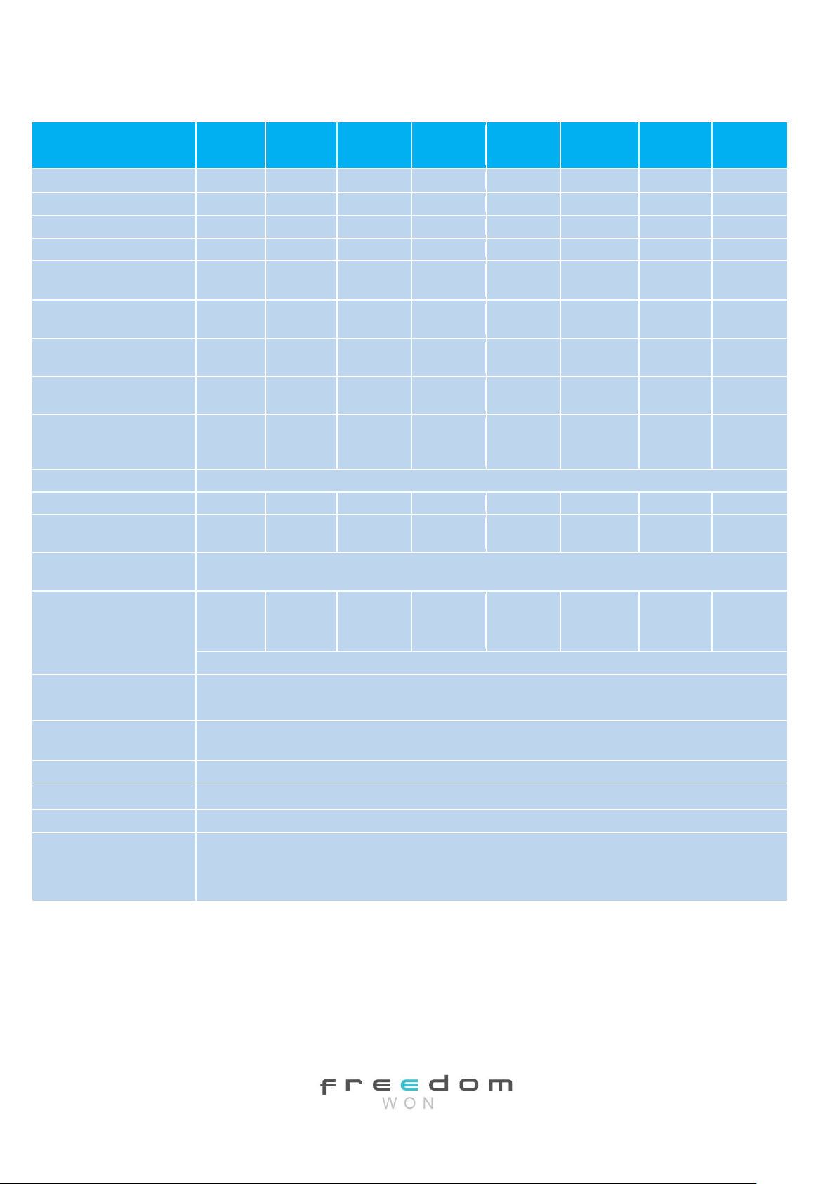
Table 2.1 provides an overview of the 52V Freedom LiTE Home and Business range. There
are eight Freedom LiTE models in the Home and Business range, as included in the table,
classified in terms of energy capacity.
An image with numbered labels pertaining to the following paragraphs is provided in Figure
2.1. The model number denotes with the first number [1] the total energy storage capacity
in kWh of each model. The second number [2] denotes the maximum amount of energy in
kWh that should be withdrawn per daily cycle (on average) in order to optimise the life of
the lithium cells. This equates to 80% of the total for each model i.e. 80% depth of discharge
(DoD). Note that all Freedom LiTE batteries offer a maximum of 90% DoD as standard.
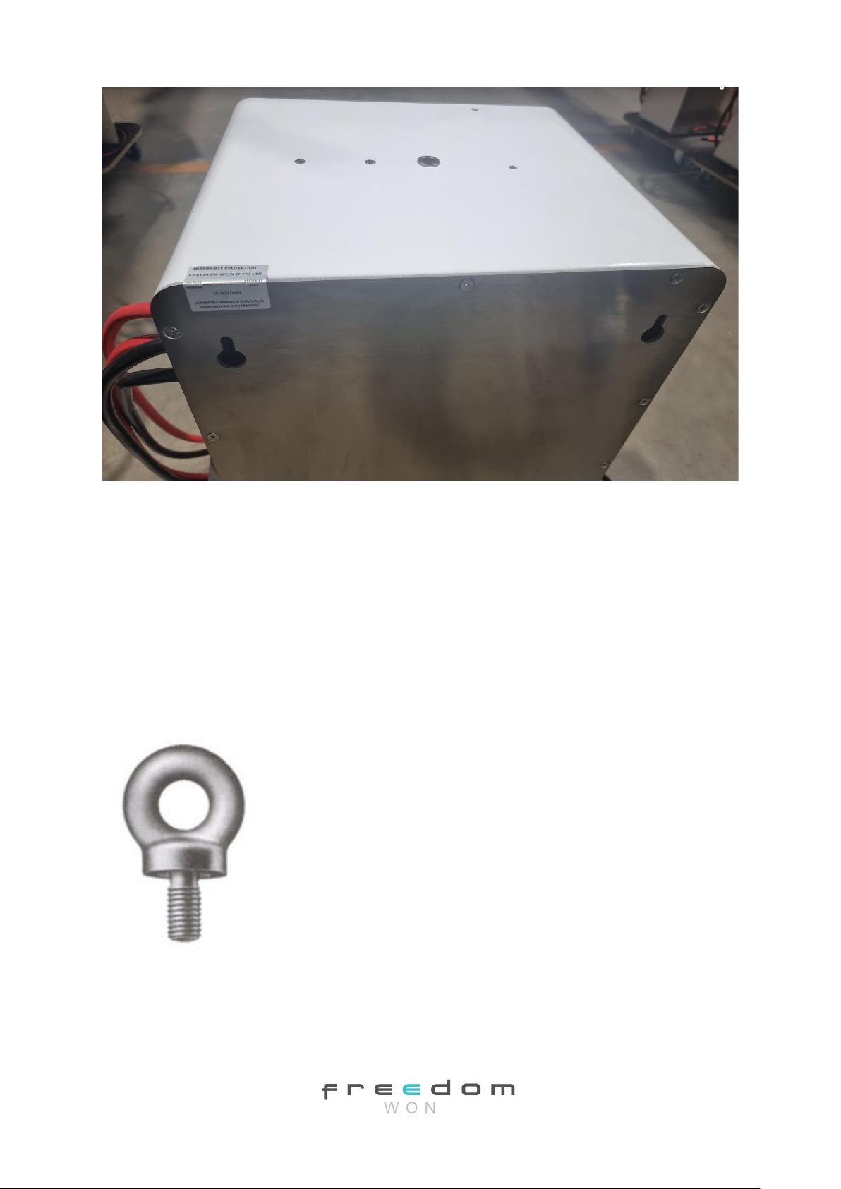
The range is very compact with the “Home” models up to the LiTE Home 20/16 intended to
be wall or floor mounted –all models are supplied standard with “keyholes” on the back for
wall mounting or plastic feet for floor mounting. The larger “Business” range is designed for
floor standing only, with either plastic feet or aluminium feet with plastic pads on the
underside.
The Ah capacity is also provided in the tables for each model for easy reference.
The maximum current for each model is governed by the rating of the built-in circuit breaker
[3], which has been sized below the maximum current capability of the lithium cells. There is
no significant cell temperature rise during operation and no active cooling of the cells is
required for this range of models. The time limit for operation at the maximum current is 30
seconds in a 60 second cycle. To ensure that the circuit breaker does not trip in normal
operation it is advised that the design of the system aims to remain at or below the
continuous current value.
For the 52V models the absolute maximum allowable voltage when fully charged is 56V,
however a more typical inverter charge setting is 55.8V. The voltage normally used as the
minimum cut off is 48V, however this will not typically be reached when operating down to
90% Depth of Discharge (DoD). The BMS will command the connected inverter with CAN Bus
interface to stop discharging the battery at 10% SoC (90% DoD), which roughly equates to
49,0V). Under high load the voltage may drop to 48V whilst still above 10% SoC. A voltage of
48V or even lower can be observed in systems without a CAN Bus interface or where the
standby current draw on the inverter has caused the battery to be discharged below 10%
SoC. The battery breaker will eventually trip the battery at around 47V to protect the cells
from undervoltage.

Freedom LiTE Installation Manual Revision 14
P a g e 3 | 30
Figure 2.1 Labelled Image of the Freedom LiTE Home 15/12 (Labelling corresponds with the
text)
1. Gross Capacity
2. 80% Capacity recommended for daily cycling (max available is 90%)
3. Breaker
4. Power Cables
[2]
[1]
[3]
[4]
[5]
[6]
[7]
[8]
[9]
[10]
[12]
[11]
[14]
[13]
[15]

Freedom LiTE Installation Manual Revision 14
P a g e 4 | 30
5. Location of DB15 Analogue and Relay Control Port on older models (note that for
production from 9 September 2019 this port is no longer provided owing to migration
of all interfacing to CAN Bus)
6. CAN Bus Sockets x 2 (RJ45) (one socket must contain a termination resistor if end of
line)
7. USB Programming Port (not visible in photo). Note that in models manufactured prior
to May 2020 this port is a DB9 plug.
8. Reset Button (not visible in photo)
9. State of Charge Display (note some models have a multicolour ON button to depict
the state of charge according to a colour wheel sticker surrounding the ON button –
see Figure 2.2.
10. Error Light (for the multicolour ON button models an error is depicted by a brief red
flash)
11. On Button
12. Off Button
13. Lifting Eye Bolt Hard Point (not visible in photo)(eye bolt not provided)
14. Manoeuvring Handles
15. Feet
Figure 2.2 Colour Wheel on Some Models Depicting the SoC of the LiTE
The weight of each model is given in Table 2.1. The Freedom LiTE Home 5/4, 10/8 models
can be manually handled by two people. The 15/12 and 20/16 can be manually handled by
four people. The larger units may require lifting equipment of varying degrees for handling
and installation as explained later in this document.

Freedom LiTE Installation Manual Revision 14
P a g e 5 | 30
The dimensions given are for the principle outlines of the aluminium housing and exclude
items that protrude such as the DC cable glands and the circuit breaker handle.
The DC cables exit the unit through glands located on the top right-hand side of the casing
and vary in number according to the model [2 in Figure 2.1]. The correct cable lugs for
connecting these leads to the inverter must be in hand when doing an installation. If there
are several inverters and charge controllers that need to be connected to the battery it is
advisable to install a DC connector box to use as a junction point from which to branch out
to all the battery connected equipment.
Two RJ45 sockets [6] are provided, one for connecting the CAN interface from the battery to
the system controller or directly to the inverter depending on the brand, and another for
connecting the battery to another battery or for a termination resistor (more detail later in
manual).
A USB Type B “printer” plug [7 - concealed] is fitted to the upper left-hand side of the
housing for use by technicians for programming the required profile onto the BMS or
updating firmware. The standard profile is loaded by Freedom Won prior to delivery but
installers are advised to keep the correct cable to allow Freedom Won or the distributor to
program batteries remotely on behalf of the installer via the installer’s Windows laptop, if
necessary. One cable is provided with each battery.
An error reset button [8 - concealed] is positioned adjacent to the USB plug.
Freedom LiTE is also fitted with a State of Charge (SoC) display [9], which includes a red LED
error indicator [10] and below it a “low power” indicator. Some models have a multicolour
ON button light that depicts the SoC according to a colour wheel that surrounds the OB
button (Figure 2.3). If there is an error recorded on the BMS, the ON button light will flicker
red in between the colour that is reflecting the current SoC.
Figure 2.3 USB Type B “Printer” Cable for Programming Freedom LiTE

Freedom LiTE Installation Manual Revision 14
P a g e 6 | 30
Table 2.1 Freedom LiTE Range Overview
Freedom LiTE
Home
5/4
Home
10/8
Home
15/12
Home
20/16
Home
30/24
Business
40/32
Business
60/48
Business
80/64
Total Energy Capacity [kWh]
5
10
15
20
30
40
60
80
Energy, 80% DoD [kWh] (1)
4
8
12
16
24
32
48
64
Energy, 90% DoD [kWh]
4,5
9
13,5
18
27
36
54
72
Current Capacity [Ah]
100
200
300
400
600
800
1200
1600
Max & Continuous Charge
Current Limit[A] (2)
100
200
300
400
600
600
800
800
Max & Continuous Charge
Power Limit [kW] (2)
5
10
15
20
30
30
40
40
Max/Continuous Discharge
Current Limit [A] (2)
200/100
300/200
480/300
480/400
750/600
750/600
1000/800
1000/800
Max/Continuous. Discharge
Power Limit [kW] (2)
10/6
15/10
24/15
24/20
38/30
38/30
50/40
50/40
Max Recommended Inverter
Total Rated Continuous
Power [kVA]
8
10
15
15
25
25
35
35
Nominal Voltage [V]
52V, to suit 48V Inverters, min 47V, max 56V
Weight [kg]
49
89
130
173
260
326
508
637
Dimensions on or against wall -
Height x Width x Depth [mm]
500x
340x290
745x
340x290
745x
490x290
745x
640x290
1300x
490x290
1300x
522x370
1300x
743x370
1300x
1009x370
Enclosure and Environmental
Conditions
Aluminium enclosure painted white, for indoor or fully protected under-cover environments, rated to IP20.
DC Connection - Integrated
Cables, [no. and size per
electrode] (3)
1x 50mm2
1 x 50mm2
2 x 50mm2
2 x 50mm2
2 x 95mm2
2 x 95mm2
2 x 95mm2
2 x 95mm2
Note: for Australian market external DC isolator required on + and -
Control Interface
RJ45 Socket x 2 –CAN Bus for Interfacing with Compatible Inverters and System Controllers, and communication
for the connection of parallel batteries –note that parallel batteries must all be of the same model.
Protection
Shunt Trip Circuit Breaker sized to suit max current, can be tripped by BMS if critical fault, manual reset. Includes
overcurrent, cell under and over voltage, temperature, weak cell detection, minimum SOC control
Human Interface
State of Charge Display (0 to 100%), Error light, Error Reset Button, USB Plug for Programming
Warranty [4]
10 years or 4 000 cycles for average 80% DoD, and max 90% DoD (refer to product warranty for more details)
Service Life [4]
>16 years (>5 500 cycles) expected life at 70% DoD (1), >20 years (>7 500 cycles) at 50% DoD
Essential Accessories
Note that for connecting the battery to a PC a USB “printer” cable is required (one is supplied with each battery)
CAN Bus Termination Resistor –one required per battery (one included with battery)
CAN Bus Cable (RJ45 LAN Cable) –one required per battery (not supplied with battery). Note some inverters will
require a special (non-standard pin configuration) cable –see installation manual
Notes to Table 2.1
1) DoD = Depth of Discharge, recommended 80% DoD for average daily discharge, 70% DoD on average for optimal life –
max for normal operation 90% DoD, max for system in standby 100% DoD.
2) Max load duration –30 seconds per 60 second cycle. 1.5 x Max overload can be handled for 5 seconds.
3) Fly Leads 1,8m long, power cable Red = Positive, Black = Negative, conductors in table refer to one electrode i.e. per
positive and negative connections

Freedom LiTE Installation Manual Revision 14
P a g e 7 | 30
4) End of Life (EoL) defined as cell dropping to 60% of Beginning of Life (BoL) capacity for expected life and 70% of BoL
capacity for warranty.
The ON button [11] and OFF button [12] are located beside the SoC display.
All LiTE’s have feet as standard, whether needed or not [15].
A hard point is supplied on the top for the 15/12 and 20/16 models [14] for inserting an eye
bolt that can be used for hoisting the battery onto the wall mountings. The LiTE 30/21 and
above are supplied with permanently installed eye bolt(s).
3. Transport, Handling and Mounting
The Freedom LiTE units are packaged in protective foam inside a wooden crate with pallet
type feet, which allow lifting with a forklift or a pallet jack. The Freedom LiTE Home 5/4 and
10/7 models are easily handled by two people. The 15/11 and 20/14 models may be
manually handled by four people. The 30/21, 40/28, 60/42 and 80/56 models must be
handled with care by a forklift or pallet jack of the required lifting capacity rating.
If it is necessary to transport the LiTE up or down multiple stairs in order to get them to the
point of installation in the premises it may be preferable to select a 20/16 or smaller and
connect multiple in parallel, rather than selecting a single larger model.
The “Home” series is designed for wall mounting to preserve room and floor space. Each
model is hung on two Rawl Bolts. The Rawl Bolts are inserted into correct diameter
predrilled holes in the wall. The bolts must first be tightened substantially so that the
internals of the Rawl Bolt have gripped tightly into the wall, and then the bolt must be
turned out slightly with the head protruding so that about 5mm of the bolt shank is
visible. This pre-tightening prevents the bolt from being pushed into the wall when
mounting the LiTE. The Freedom LiTE has two keyhole shaped holes on the back, which are
shaped to fit over the bolt heads, and then a narrowed section secures around the bolt
shank as the unit is lowered into its final position. The 5/4, 10/7, 15/11 and 20/16 models
are hung using M8 bolts. The centre to centre spacing of these bolts must be applicable to
the model being installed. It is critical that these bolts are mounted within 1mm of the
correct dimension and must be perfectly level.
Figure 3.1 Bolt Mounting Keyhole on Rear of LiTE Casing. Warranty Seal and Eye Bolt Hard
Point Also Visible

Freedom LiTE Installation Manual Revision 14
P a g e 8 | 30
Eye bolts fixed to the top of the battery can be used for hoisting the unit up to the required
height for fitting to the wall (excluding 5/4 and 10/8, which can be lifted manually). The eye
bolt is not supplied with the LiTE 15/12 and 20/16, one must be on hand for installation and
can be removed after installation (ensure that you have one M12 x 1,75 thread eye bolt
rated for 450kg or more).
Lifting the batteries by the eye bolts should be performed using a mobile gantry crane or a
high lift pallet jack.
Figure 3.2 Eye bolt Example

Freedom LiTE Installation Manual Revision 14
P a g e 9 | 30
Figure 3.3 Eye bolt Installation on a LiTE 15/12 model (Remove after installation)
The units can alternatively be lifted to the right height and onto the hanging bolts using a
high-lift pallet jack such as shown in Figure 3.4. A site assembled gantry with electric winch
is shown in Figure 3.5.
Figure 3.4 High Lift Pallet Jack

Freedom LiTE Installation Manual Revision 14
P a g e 10 | 30
Models up to LiTE Home 20/16 are fitted with lifting or manoeuvring handles to make
placement easier. See Fig 4.2.
Fig 3.5 Site Assembled Gantry with Electric Hoist

Freedom LiTE Installation Manual Revision 14
P a g e 11 | 30
Caution:
1. Great care must be taken to ensure that the Rawl Bolt has properly located into the
narrowed section of the mounting hole before removing the support.
2. Handle the Freedom LiTE with great care when lifting and manoeuvring. It should
remain either lying flat on its back, or vertically upright (it should not be placed
upside down or on its front face.
3. Do not allow the pallet jack to tilt forward with the weight too far to the front.
4. Take care not to knock any of the protruding items against obstacles during handling
such as the DC cabling and plugs and the circuit breaker handle.
5. Take care not to scratch the LiTE during handling. Packaging foam should be used to
protect the paint when being handled on a trolley or pallet jack.
6. Always ensure that lifting equipment and slings are adequately rated for the lifting
weight.
7. Ensure that the eye bolts are fully screwed into the hard point thread on the top of
the unit before lifting.
8. Wear personal protective equipment such as safety shoes and gloves while handling
and mounting the Freedom LiTE
9. Always ensure that you have enough people on hand to perform the operation safely,
i.e., at least one person to guide and stabilise and one person to hoist or handle the
pallet jack or gantry.
10. The gantry can be configured for wall mounting –when using the gantry in this
configuration absolute care must be taken to prevent the gantry from being pulled
over by non-vertical tension on the rope.
Mounting and Environmental Requirements
The LiTE Home and Business models are designed strictly for indoor use away from moisture
and direct sunlight.
No specific venting is required since the LiTE emits no hazardous gases, however air
circulation may be required to ensure room temperature is maintained at reasonable levels,
preferably below 25˚C (see LiTE warranty for information on upper temperature limits for
hot environments).
Room heating may be required in cold climates to keep the room above 0˚C, since charging
of the LiTE is not permitted below 0˚C. Ambient environments that regularly exceed 30˚C
should employ room cooling if practicable to ensure optimal LiTE service life.
The LiTE may be mounted directly against a wall or on the floor. There is no minimum
requirement for spacing around the battery from other objects provided that these objects
do not generate heat, corrosive gases, or moisture, and that the vents on the sides of the
battery are not blocked. Note however that access is required to the USB programming port
on the left side, and the CAN Bus plug sockets and cable exits on the right side.

Freedom LiTE Installation Manual Revision 14
P a g e 12 | 30
Where multiple LiTE batteries are installed in one system, the spacing between each battery
should not be less than 250mm.
The LiTE should be installed at least 500mm away from a heat source such as inverters,
charge controllers, boilers, or flues.
The LiTE Home and Business enclosure is rated to IP20. The integrated protection circuit
breaker is rated for IP40.
4. Connecting the Freedom LiTE
4.1 Power Cables
The Freedom LiTE is simple to connect to the battery inverter. First of all, you will connect
the 48V positive and negative cables to the inverter terminals using the applicable lugs.
Caution: Prior to connecting the positive and negative cables to the inverter be sure to
check that the main battery circuit breaker is switched off. This will ensure that there are
no short circuits between the loose ends of the cables.
The cables are supplied with the Freedom LiTE, permanently fixed into the unit and secured
onto the casing using compression cable glands. Attach crimp lugs to the ends of both cables
ensuring that the correct terminal size is used, and the lug is matched to the size of the
cable. The positive cable is red, and the negative cable is black. This is confirmed by + and –
signs on the battery casing beside the respective cables. See Tables 2.1 for the cable size
and quantity fitted to each Freedom LiTE model. The cable cross sectional area is based on
an acceptable voltage drop with the inverter being mounted on the wall adjacent to the
Freedom LiTE battery so that the cable run is less than 5m (note however that the standard
cable length is 1,8m, longer cables available on request).
Cable runs longer than 5m should be assessed and larger cables considered for extending
the Freedom LiTE cables to minimise voltage drop. Double Insulation welding cable is
recommended.
The cables may be routed through trunking and connected into the inverter on the positive
and negative terminals respectively. The inverter terminals on most inverters can then be
used for linking up the charge controller(s) to the DC Bus. On Installations where there are
too many inverters and/or charge controllers to connect to the DC bus using the inverter
terminals as a junction point a DC connector box is required. Where more than one cable is
fitted per pole, the battery cables can be separately routed directly to separate equipment
(inverters and charge controllers) –if this is done the installer must take care to ensure that
any one of the cable pairs will not be overloaded. The cables for each pole are connected
together inside the battery.

Freedom LiTE Installation Manual Revision 14
P a g e 13 | 30
4.2 DC Bus Design Notes
4.2.1 DC Isolator
The LiTE range includes an integrated battery DC breaker/isolator that breaks the positive
cable continuity inside the battery. This breaker, on all Home and Business models, is rated
for a 36kA fault (short circuit) current. The system therefore does not require another DC
isolator or breaker except where required by local regulations, for example in relation to
conformance with the Clean Energy Council of Australia battery design Best Practice Guide,
which states, “Should the internal battery isolator not offer isolation of BOTH the positive
and negative terminals of the battery, an external isolator is required that can isolate both
the positive and negative cables/terminals of the battery.”
The approximate short circuit current values of each battery model are provided in the table
below:
Table 4.1 Short Circuit Current for LiTE Home and Business Models
Freedom LiTE
Home
5/4
Home
10/8
Home
15/12
Home
20/16
Home
30/24
Business
40/32
Business
60/48
Business
80/64
Short Circuit Current [A]
1500
2100
3100
3600
4700
5100
5800
6200
The external isolating device required for installations that are required to conform to the
CEC of Australia should be designed to withstand these fault levels (short circuit currents) as
well as the applicable current rating of the battery or the combined current ratings of all
batteries connected to the isolating device.
A single line diagram for a typical residential installation is provided in below Figure 4.1.
4.2.2 Multiple Battery Connection
Systems with multiple batteries must be installed such that the DC cables are the same
length on all batteries, which must be routed to a common DC combiner such that the
current pathway for all batteries to the point of load or charge is the same. The DC
Combiner may be the terminals on an inverter if there is enough space, or a dedicated DC
Combiner Box.

Freedom LiTE Installation Manual Revision 14
P a g e 14 | 30
Figure 4.1 Typical Residential Installation –Single Line Diagram

Freedom LiTE Installation Manual Revision 14
P a g e 15 | 30
4.3 Control Cables –Overview
For controlling external devices, you will need to connect the CAN Bus cable that allows the
Battery Management System inside the Freedom LiTE to control and interface with these
devices.
The CAN Bus connection is made using the RJ45 plug with the pin configuration on the
battery plug end provided in Table 5.1.
Table 5.1 Colour Coding and Pin Configuration for CAN Bus UTP Control Cable RJ45 Sockets
on the LiTE
RJ45 Pin No.
Standard Ethernet Cable Colours
Wire Function
Pin 1
Orange/White
Not connected
Pin 2
Orange
Not connected
Pin 3
Green/White
Not connected
Pin 4
Blue
Not connected
Pin 5
Blue/White
Not connected
Pin 6
Green
Not connected
Pin 7
Brown/White
CAN High
Pin 8
Brown
CAN Low
For Victron connections a standard LAN cable will work. For all other inverters a custom pin
configuration is required. For SMA inverters a special cable is required because of the
resistor required on the inverter end of the cable –please refer to the respective inverter
brands manuals for their pin configuration or contact Freedom Won for assistance. The
special SMA cable is available from Freedom Won.
4.4 CAN Bus Control –Detailed Description
CAN is a widely used communication protocol in systems with many devices that must
report their status or send commands to other devices on the same network. The Freedom
LiTE BMS can transmit messages and commands in CAN protocol to provide information to,
but more importantly to control, external devices. CAN allows great versatility and provides
a simple installation because there are only two wires required in this form of
communication, namely CAN High and CAN Low. In order for an inverter or charge
controller to be controlled by CAN it must first of all be equipped with a CAN interface as
well as a suitable method of connecting the CAN wires. Further to this the Freedom LiTE
BMS must be programmed with a CAN messaging profile that is developed for the inverter
or charge controller being used. This profile must be specifically developed for each inverter
model or model range. To date Freedom Won has developed CAN profiles for an extensive
list of inverter brands. Refer to the Freedom LiTE and eTower to Inverter Interfacing Guide
(https://www.freedomwon.co.za/wp-content/uploads/Freedom-LiTE-eTower-Interfacing-
Guide.pdf) for the complete list .

Freedom LiTE Installation Manual Revision 14
P a g e 16 | 30
Freedom Won welcomes any requests to produce BMS CAN profiles for other inverters that
are CAN equipped for the BMS interface.
The CAN interface can provide the following functionality to compatible devices:
i. Charge Current Limit of all LiTE’s connected
ii. Discharge Current Limit of all LiTE’s connected
iii. Actual State of Charge (minimum of all lights connected)
iv. Actual Battery Temperature (highest of all lights connected)
v. Actual Voltage
vi. Actual Current (total of all LiTE’s connected)
vii. Maximum real time charge voltage setpoint
viii. Battery Name
ix. Highest Cell Voltage of all LiTE’s connected
x. Lowest Cell Voltage of all LiTE’s connected.
xi. Firmware Version
xii. Ah capacity of all batteries connected
xiii. Advanced communication between all connected LiTEs
The CAN 2.0 Part A and Part B standard uses the SAE J1939 standard in the LiTE. It is
necessary to install a 120 Ohm resistor on each extreme end of the CAN cable (splices or
branches do not require a resistor). Most devices operating on CAN have two plugs to
connect in and then out again on the CAN Bus. The first and the last device in the chain must
have a termination resistor plugged into the spare (second) plug. The LiTE resistor plugs are
available from the inverter manufacturer and from Freedom Won. Ingeteam has a separate
CAN terminal block for bare wires to be inserted from the BMS and these units have an
internal resistor fitted into the device. From August 2018 all Freedom LiTE models have two
CAN plugs for parallel configurations (Figure 4.2) and allowing fitment of the termination
resistors on the end of line units. Where one LiTE is installed or where it is the end of line
CAN device, the LiTE must be fitted with a termination resistor.
The LiTE is supplied with a termination resistor as standard. The other devices must be fitted
with the correct termination resistor for that particular brand because the pin configuration
may differ from the battery plug.
The third-party device manuals must be referenced for all details regarding connecting the
CAN interface.
Most brands use 500kbps. If 250kbps is required it is available on the LiTE with a specific
profile loaded, which must be loaded during commissioning by your distributor or Freedom
Won technical support.
If you did not purchase a CAN Bus cable to suit your inverter you can make your own
according to Table 5.2. Fig 5.1 provides the standard colour coding for an Ethernet cable
(note that there are other variations so double check this).

Freedom LiTE Installation Manual Revision 14
P a g e 17 | 30
Fig 4.2 Pin Configuration for standard Type T-568B RJ45 plug
Table 5.2 Inverter End Pin Configuration for CAN Bus Control Cable for some supported
inverters –for further information refer to the Freedom LiTE and eTower Interfacing Guide.
Inverter Brand
CAN L
CAN H
Comments
Axpert / Kodak: King, Max and
VMIII
Requires a CAN Bus to RS485
converter that is available from
Freedom Won. Enquire from
Goodwe: ES
Pin 5
(blue/white)
Pin 1
(orange/white)
LiTE to Type 1 RJ45 cable required
for connecting CAN Bus from LiTE to
Goodwe –available from Freedom
Won. Enquire from
Growatt / Sunforce: 5kW
Pin 4 (Blue)
Pin 5
(Blue/white)
LiTE to Type 1 RJ45 Cable required
for connecting CAN Bus from LiTE to
inverter, available from freedom
won. Enquire from
Imeon: 3.6 and 9.12
Pin 2 (orange)
Pin 1
(orange/white)
Type Imeon RJ45 cable required for
connecting CAN Bus from LiTE to
inverter –available from Freedom
Won. Enquire from
Ingeteam: Ingecon Sun, Storage
1Play, 3TL and 6TL
Open terminal
Open terminal
Labelled on inverter
Koyoe: 3kVA Hybrid
Please connect Freedom Won if you
need to connect on of these
inverters to a LiTE
MLT: PowerStar 10, Oasis,
Nomad MPPT
Pin 5
(blue/white)
Pin 4 (blue)
The MLT range of products offers
complete CAN Bus interfacing.
PowerStar 10 and Oasis –use a LiTE
to Type 1 RJ45 Ethernet cable –
available from Freedom Won.
Nomad –a CAN terminal plug is
provided on the PC board of the
Nomad with a resistor that can be
enabled with a bridge. Please see
Nomad manual.
Revo: 5kVA
Pin 5
(blue/white)
Pin 4 (blue)
Requires Type 1 CAN Bus cable –
available from Freedom Won.

Freedom LiTE Installation Manual Revision 14
P a g e 18 | 30
Enquire from
SMA: Sunny Island
Pin 5
(blue/white)
Pin 4 (blue)
Bridge Pin 3 and Pin 6 on Inverter
end of cable with a 120Ωresistor
Solax
Pin 1
(orange/white)
Pin 2 (orange)
This brand requires a special cable
to accommodate pin assignment on
inverter –please contact Freedom
Won for more information.
Sofar Solar: 3kW
Pin 2 (orange)
Pin 1 (orange/
white)
Solis / Kodak: 3 to 6kW Models
LiTE to Type 1 RJ45 cable required
for connecting CAN Bus from LiTE to
Inverter
Studer: Variotrack and Xtender
Models
The Studer X-Com CAN can be
configured to suite on of the
options in Table 5.1 using the
jumpers supplied with the X-COM
can unit.
Sunsynk/ Daye: 5kW and 8kW
Hybrid
Pin 5
(blue/white)
Pin 4 (blue)
Type 1 CAN RJ45 cable required
Victron (GX Controllers)
Pin 8 (brown)
Pin 7 (brown/
white)
Note that the Freedom LiTE plug uses pins 7 and 8 for CAN H and CAN L.
If your inverter is not included in this table, please contact Freedom Won for assistance.
All BMS interfaces above operate at 500kbps baud rate except for Ingeteam, which operates
on 250kbps. Please enquire with Freedom Won Technical Support to change the default
500kbps to 250kbps.

Freedom LiTE Installation Manual Revision 14
P a g e 19 | 30
4.5 Parallel Configurations
It is permissible to connect up to 20 Freedom LiTE’s in parallel provided that the Freedom
LiTE model size used is the same throughout. It is however more cost effective to purchase
one larger Freedom LiTE model than connecting multiple units in parallel. Parallel
installation is usually reserved for future expansion where it is not feasible to purchase a
model large enough upfront (financial constraints).
One LiTE is programmed as the Master, while the rest of the LiTE’s connected to the DC bus
are programmed as Slaves.
The parallel LiTE’s must be connected to each other via the CAN Bus using standard LAN
cable.
Where CAN Bus is used to control the inverter(s) and charge controller(s), the CAN Bus from
any battery can be connected to the inverter directly or the system controller, depending on
the product brand. This battery is then “daisy chained” to all other batteries in the system.
This is achieved by providing two RJ45 sockets on the battery –refer to Figure 5.2. On the
last battery in the chain, one socket is used for an end of line (termination) resistor, and the
other socket for connecting to the next item of equipment, whether it be another battery,
an inverter, a solar charge controller, or system controller.
Other manuals for Lite Home 5/4
1
This manual suits for next models
7
Table of contents
Other Freedom Won Camera Accessories manuals

Freedom Won
Freedom Won Lite Home 5/4 User manual

Freedom Won
Freedom Won Lite Commercial Series User manual

Freedom Won
Freedom Won LiTE Home 10/8 User manual

Freedom Won
Freedom Won eTower User manual

Freedom Won
Freedom Won Lite Commercial Series User manual

Freedom Won
Freedom Won Freedom Lite Home 15/12 HV User manual