Freeman WE4 User manual

A Product of
Sherwood, Oregon USA
Important: Be certain to specify the
serial number of your Water Extractor
when ordering parts.
Starting in 2020, with
Serial Number: ASC-0WE4-466
Operators Manual
Water Extractor
PB000WE4OPS66
Model WE4
A Product of
Sherwood, Oregon USA
For Serial Number: ASC-0WE4-466
Suggested
Spare Parts
Water Extractor
Model WE4
Important: Be certain to specify the
serial number of your Water Extractor
when ordering parts.
89-119

This page is intentionally left blank.

07/2020 1
WARNING
California Proposition 65 Warning
Diesel engine exhaust and some of its
constituents are known to the State of
California to cause cancer, birth defects, and
other reproductive harm.
Battery posts, terminals and related acces-
sories contain lead and lead compounds,
chemicals known to the State of California
to cause cancer, birth defects, and other re-
productive harm. Wash hands after handling.
Other chemicals in this vehicle are also known
to the State of California to cause cancer, birth
defects, and other reproductive harm.

207/2020
Safety
“THE BEST SAFETY DEVICE IS A CAREFUL OPERATOR”
AlwaysturnosystemcontrolandLock-Outtheelectricalsupplytothemachine
before inspecting, adjusting or servicing the machine.
Do not clean, lubricate, or make any adjustments on the equipment while it is in operation.
Do not start the equipment until you are certain everyone is clear of the machine and have
ensured there are no tools on the unit.
Do not work around equipment in loose clothing.
Do not attempt to service any equipment while the motor is running.
Inspection Covers and Safety Shields should only be removed by authorized
service personnel.
After servicing do not place the equipment back into operation until all Safety Shields and
Devices have been replaced. Operation without Safety Shields and Devices can place the
operator into a hazardous situation.
Do notopenorworkontheIn-FeedSystemuntiltheowofmaterialhasbeenstopped
andtheMotoriso.
Do not make any adjustments or reach under any load bearing surfaces while loaded.
INSTRUCTALLOPERATORSONSAFETYPRECAUTIONS.
WARNING: SOME ILLUSTRATIONS IN THIS MANUAL SHOW THE MACHINE
WITHOUT SHIELDS TO ALLOW FOR A BETTER VIEW THE AREA BEING
ADDRESSED. THE MACHINE SHOULD NEVER BE OPERATED WITH ANY
OF THE SAFETY SHIELDS REMOVED.

07/2020 3
General
The following pages contain general safety warnings which
supplementspecicwarningsandcautionsthatcanbefound
in the operators manual (PB0WE4AOPS66) that is included
withthisunit.AllFreemanmanualscanalsobefoundonlineat
www.alliedsystems.com. All electrical and hydraulic equip-
mentispotentiallyhazardous.Youmustthoroughlyreview
and understand this Safety Section before attempting to op-
erate, troubleshoot, maintain or service this water extractor.
Time,moneyandeorthavebeeninvestedinmakingyour
Water extractor a safe product. The dividend from this
investmentisYOURPERSONALSAFETY.
However,itmustberealizedthatnopower-drivenequip-
ment can be any safer than the person behind the controls.
If you don’t operate and maintain your Freeman water
extractorsafely,oureortswillhavebeeninvain.
The safety instructions and warnings, as documented in this
manual and operators manual shipped with the machine,
provide the most reliable procedures for the safe operation
and maintenance of your water extractor. It’s your respon-
sibility to see that they are carried out.
Allied Systems Company cannot anticipate all worksite
conditions, local regulations, etc. It is the responsibility
of the end user to be aware of and obey any specic
worksite, local, state, or national regulations or proce-
dures that are applicable to operating this water extractor.
NOTE: All possible safety hazards cannot
be anticipated so as to be included in this
manual. Therefore, you must always be alert
to potential hazards that could endanger
personnel and/or damage the equipment.
Safety Symbols
The following symbols/terms are used to emphasize
safety precautions and notices:
DANGER
The “DANGER” symbol indicates a hazardous
situation which, if not avoided, will result in death
or serious injury. Carefully read the message that
follows to prevent serious injury or death.
WARNING
The “WARNING” symbol indicates a hazardous
situation which, if not avoided, could result in death
or serious injury. Carefully read the message that
follows to prevent serious injury or death.
CAUTION
The “CAUTION” symbol indicates a hazardous situ-
ation which, if not avoided, could result in minor or
moderate injury, or equipment damage. Carefully
read the message that follows to prevent minor or
moderate injury.
NOTICE
The “NOTICE” symbol alerts to a situation
that is not related to personal injury but may
cause equipment damage.
NOTE: …
The term “NOTE” highlights operating
procedures or practices that may improve
equipment reliability and/or personnel per-
formance, or to emphasize a concept.
Operation Warnings
WARNING
Warning: Failure to observe the following safety
rules may result in extreme personal injury, dis-
memberment or death. It is the operator’s respon-
sibility to understand the proper and safe use of
this water extractor.
Make sure that you read, understand, and obey all of
the safety precautions and operating instructions in
the operator’s manual.
• Keep this Operator’s Manual and the Safety Card (Al-
liedform#89-120)withthewaterextractoratalltimes.
• Do not operate the water extractor unless you are
authorized and trained to do so.

407/2020
Maintenance Safety
• Perform all routine maintenance outlined in this
Operator’s Manual in the time intervals indicated.
• Maintenance, lubrication and repair of this machine
can be dangerous unless performed properly. In order
to ensure safety, each person working on this water
extractor must have the necessary skills, information,
tools and equipment, and satisfy himself that his work
method is safe, correct, and meets his own company’s
requirements.
• Do not attempt to make adjustments, or perform repairs
unlessyouareauthorizedandqualiedtodoso.
• Never attempt to service energized
equipment.
• Alwaysshutoandsecure
power when servicing the wa-
ter extractor.
• Disengage the water extrac-
torandshutopower,and
wait for all movement to
stop
before adjusting, lubricat-
ing, cleaning, or
servicing the water extractor.
• Tag the Control Box with a ”DO NOT START”(See
CautionStatementonPage10)
• Any unauthorized modications made to the water
extractor by the customer or parties other than Allied
Systems will relieve Allied Systems Company and your
Freemandealerofanyliabilityfordamageorinjury.
• ReplaceanywornpartsonlywithgenuineFreeman
parts. Call your dealer for assistance.
• Unlessspeciedinserviceprocedures,neverattempt
maintenance or lubrication procedures while the water
extractor operating.
• Before making adjustments to the electrical system,
turnthepowero.
• Do not operate the water extractor if you are aware
of any malfunctions, needed maintenance or repairs.
• Stop the water extractor immediately if any problems
arise.
• Never operate the water extractor without all safety
shielding in place.
• Keep hands, feet, hair, jewelry and clothing away from
moving parts.
• Avoid wearing loose clothing which can easily be
caught in moving parts.
• Knowyourjob-siterules.Somehavesite-specicdi-
rections and procedures. The methods outlined in the
operators manual provide a basis for safe operation
of the water extractor. Because of special conditions,
yourcompany’sproceduresmaybesomewhatdierent
from those shown in the operators manual.
• Do not start the water extractor if it has been marked
with a “DO NOT START” or “RED” tag.
• Alert personnel in the area before starting the water
extractor, and make sure everyone is clear.
• Each country has its own safety legislation. It is in the
operator’s own interest to be conversant with these
regulations and to comply with them in full. This also
applies to local bylaws and regulations in force on a
particular worksite.
• Should the recommendations in this manual deviate
from those in the user’ country, the national regulations
should be followed.
• Never attempt to disconnect any of the safety devices
built into the water extractor.
Hydraulic Hazards
Be aware of the hazards of pressurized hydraulics:
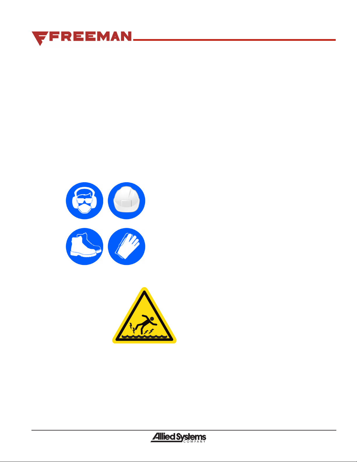
• Wear personal protective equipment,
such as gloves and safety glasses,
whenever servicing or checking a
hydraulic system.
• Assume that all hydraulic
hoses and components
are pressurized. Relieve
all hydraulic pressure
before disconnecting any
hydraulic line.
• Never try to stop or check for a hydraulic leak with any
part of your body; use a piece of cardboard to check
for hydraulic leaks.
• Small hydraulic hose leaks are extremely danger-
ous, and can inject hydraulic oil under the skin, even
through gloves.
• Infection is possible when hydraulic oil
penetrates the skin. See a doctor
immediately to prevent loss of limb or death.

07/2020 5
Safety Equipment
• Ensure test equipment is in good condition.
• If an instrument must be held while taking measurements,
ground the case of the instrument before energizing
equipment.
• Do not touch live equipment or personnel working on
live equipment while holding a multimeter. Some types
of measuring devices should not be grounded—do not
hold such devices while taking measurements.
• Prevent personal injury or equipment damage by using
a lifting device with a lifting capacity greater than twice
the weight of any equipment to be lifted.
• Always use personal protective equipment (PPE) ap-
propriate to the situation. This may include the use of
hearing protection, eye protection, a respirator, a hard
hat, leather gloves, steel toed boots, etc.
Electrical Hazards
• An electric shock could be fatal.
Ensure power to the water extractor
is“OFF”beforeopeningelectrical
panels.
• All electrical cables and con-
nectors must be in good
condition (free of corro-
sion, damage, etc). Use
caution in wet weather to
avoid danger from electri-
cal shock. Never attempt electrical testing or repair
while standing in water.
• Do not wear electrically conductive jewelry, clothing,
or other items while working on the electrical system.
Compressed Air Hazards
• When using compressed air to dry parts, pressure
shouldnotexceed30psi(200kPa).
• Air pressure penetrating your skin can be fatal. Never
direct compressed air at anyone.

607/2020
Safety....................................................................................................................2
Introduction..........................................................................................................8
Overview.............................................................................................................10
Drawing’s and Schematics ..................................................................................10
Dimensions / Weight............................................................................................ 11
Lubrication .......................................................................................................... 11
Setup...................................................................................................................12
Mechanical Installation .......................................................................................12
Electrical Connection...........................................................................................12
Check Motor Rotation..........................................................................................12
Prime Pump.........................................................................................................13
ConnectWaterLinesToWaterThrottlingValve(ifequipped) .............................13
RemoveMetalShippingBracketOnFloatLevelSwitch .....................................13
ConnectAirLinetoAirNozzleOnIn-FeedChute ...............................................14
Power Unit..........................................................................................................14
Hydraulic Power Unit ...........................................................................................14
Oil Types..............................................................................................................14
OilLevelFloatSwitch ..........................................................................................15
Dual Oil Temperature Switches ...........................................................................15
Oil Cooler / Oil To Water Heat Exchanger ...........................................................15
DirectionalControlValve .....................................................................................16
Hydraulic Pump Controls.....................................................................................16
ProportionalValveManifold .................................................................................16
Control Box..........................................................................................................17
Restriction System ............................................................................................18
Table of Contents

07/2020 7
Operation............................................................................................................18
StartingtheWE-4 ................................................................................................18
TurningotheWE-4............................................................................................19
Emergency shut down .........................................................................................19
Automatic and Manual Operation ........................................................................19
Auto Anti Plug ......................................................................................................19
Plugging The Chamber........................................................................................20
Operation Sequence............................................................................................20
Adjustments.......................................................................................................22
Potentiometer Adjustments..................................................................................22
LevelDetectorAdjustments.................................................................................23
WaterThrottlingValve..........................................................................................24
FactorySettings...................................................................................................24
Maintenance.......................................................................................................24
Unplugging/Anti-plugSystem ..............................................................................24
Safety Precautions...............................................................................................25
Maintenance Precautions ....................................................................................25
ReservoirOilLevel ..............................................................................................25
Pump and Motor Coupler.....................................................................................26
ProcedureToFillanEmptyReservoir .................................................................26
Procedure to Add Oil to the Reservoir .................................................................26
Change Oil and Clean Reservoir.........................................................................26
Flushing ...............................................................................................................26
Preventative Maintenance ...................................................................................27
Troubleshooting.................................................................................................28
Pump ...................................................................................................................28
Filter.....................................................................................................................31
Gauges ................................................................................................................32
MachineFunction ................................................................................................33
Table of Contents

807/2020
Automated Water Extraction
The Freeman water extractor is an efficient, automated tool for extracting water from a
continuously fed product. Product transport is eased with compaction and water removal. A
wide variety of adjustments provide a machine to suit most products.The plunger forces water
from the product. A restriction system is activated only when the plunger is advancing. A control
box switch allows the restriction rail control system to be bypassed so that pressure is applied
continuously for setting pressures, testing, and troubleshooting.
Serial Number Location
The serial number of your water extractor is necessary for correct ordering of replacement parts.
Replacement Parts
GenuineFreemanreplacementpartsshouldbeused.Ensurepromptservicebygivingthedealer
the part description and part number, model number, and serial number.
Appearance Care
TopreservethenishonFreemanequipmentdonotuseabrasiveheavydutypowdersorsolu-
tionscommonlyusedtocleansolventbasedpaintnishes.Donotrubthenishwithpadsmade
ofplasticormetal.Thesecanscratchanddullthepaintnish.
TocleantheexteriorandinteriorpaintedsurfacesonFreemanequipmentusetrisodiumphosphate
(TSP). Any other cleaning agents should be spot tested.
Introduction

07/2020 9
Serial Number Location and Baler identification
EachFreemanWaterExtractorisidentiedbymeansofamodelnumberandserial
number.Asafurtheridentication,allpowerunitsareprovidedwithaserialnumber.
Toensureprompt,ecientservicewhenorderingpartsorrequestingrepairs,record
the serial numbers in the spaces provided.
WE-4SERIALNUMBER______________________________________________
Frontsideofmainframeundermotor.
POWERUNITSERIALNUMBER
ElectricMotor-_______________________________________________________
NOTE: The motor and pump end is considered the front of the Water Extractor.
Thesidesaredescribedasleft-handsideandright-handsideasviewedfromthe
rear while facing the chamber.
S/NLocationstartingwithASC-0WE4-464
Serial Number Plate

10 07/2020
905505...........................................................................................Hydraulic Schematic
903502............................................................................. Wiring Diagram Junction Box
910496................................................................Wiring Diagram Control Panel (IQAN)
(All Drawings can be found in the document pack shipped with this model.)
Figure 2. Left Side
Figure 1. Right Side
Overview
Drawings, Parts, and Schematics referenced
throughout the manual:

07/2020 11
Dimensions / Weight
Length:.......................................................................... 20'
Height: ........................................................................9'-9"
Width: ............................................................................. 6'
Weight: .........................Approximately9,700LbsWithOil
RestrictionRailToGroundFullyOpen: .........................9"
Motor: .........................................................40hp/460Volt
Chamber Width.............................................................24”
Chamber Height ...........................................................27”
PlungerStrokeLength..................................................42”
In-FeedOpening:................................................20”x20”
Volume....................4000CubicFeet/Hrat8Strokes/Min.
Lubrication
HydraulicOil:Mobil424orMobilDTE15Morequivalentto
aViscositygreaterthan10centistokesat180˚Fandless
than200centistokesat60˚F.
Hydraulic Reservoir Capacity: .......................110Gallon
Check Oil level:.......................................................Daily
ChangeReturnLineFilter: ....................Every 6 Months
Test Oil:...........Every 6 months and change accordingly
Change Oil:.................. *Annually if oil isn’t being tested
ChangeBreatherFilter: .........................Every 6 Months
Grease Electric Motor:..........See Manufactures Manual
*ContactFreemanServiceDepartmentfor
Recommendations on oil testing kits.
Figure 3. Dimensions
233”
100”
54”
233”
100”
54”
Overview

12 07/2020
CAUTION
Always turn o system control and lockout the
electrical supply to the machine before inspect-
ing, adjusting or servicing the machine.
Mechanical Installation
Anchor the base The water extractor location should allow
ecientjoiningtotheIn-Feedchute,andprovidepersonal
safety.Provideadequatespaceforservicing.Locatethe
discharge so the product discharge falls free, with no backup
of the product.
The water extractor should be located within a catchment
to provide for water retention and water spray drainage.
Use sixteen, grade 8, 3/4 inch bolts through the foot pads
to anchor the water extractor to a foundation of concrete
or steel. Use shims to provide a level surface.
Electrical Connection
Power unit connection The 40 horsepower motor oper-
ates at 460 volts. Supply wires should be correctly sized to
prevent the motor from stalling during machine operation
and momentary overloads and meet all relevant electrical
codesandpractices.Seewiringdiagram910496.
Main Control Panel TheOilLevelSensor,OilTempera-
ture Sensor, Motor Starters (supplied by others), and HPU
mounted Junction Box are to be wired by the customer upon
installation and must meet all relevant electrical codes and
practices.Seewiringdiagram910496.
Check Motor Rotation
IMPORTANT: Open up suction valves (see Figure
6 - pg. 13) so the hydraulic pump is flooded with
oil before turning on the motor (see Prime Pump
section - pg. 13).
MovetheSYSTEMCNTRLSwitchtoSTOP,RESTRICTION
Switch toAUTO, andANTI-PLUG switch toAUTO (see
Figure4).Removethemotor-pumpcouplercoveratthe
right side for viewing. Jog the motor to check for correct
rotation. Note the motor shaft direction of rotation (standing
atthefrontoftheWE-4viewingthemotor).Correctrotation
isclockwise(seeFigure5).Replacethecover.
4
HYD. POWER UNIT
Figure 4 - Control Panel
Motor-Pump
Coupler Cover
Figure 5 - Correct motor rotation
Motor power must be supplied through an external motor
branch circuit disconnect and magnetic starter, incorporat-
ing a motor overload disconnect device. The motor branch
circuit disconnect should have excess current prevention
devicesmeetingtheNationalElectricCodeTable430-152.
Overload disconnects should be set to the motors full load
current rating.
Emergency motor stop and low oil shutdown The emer-
gencymotorstopswitchandlowoilshutdownoatswitch
(see Figure 13 - Pg. 15) are connected to control box
terminals(seewiringdiagram910496).Connectthemotor
starterpowerasshownon910496toplacetheswitches
in series with the motor control circuit.
Setup

07/2020 13
Prime Pump
CAUTION
Always turn o system control and lockout the
electrical supply to the machine before inspect-
ing, adjusting or servicing the machine.
1.Makesurethepumpcaseislledwithclean,ltereduid
identicaltothatusedintherestofthesystem(seeFilter
andLubricationPg.14).Thepumpcasemustbefullatall
times to ensure proper lubrication of internal components.
2.Verifythatpipingiscompletedandanyinletvalvesare
open to prevent cavitation or aeration of the pump.
3.Conrmthatthedirectionofrotationofthemotormatches
thepumpinstalled(seeCheckMotorRotationPg.13).
4. Jog start the motor with the pump unloaded and operate
until the air is bled from the system.
5.Checkthepumpforexternalleakage,abnormalnoise,
and vibration.
Suction Valve in the
OPEN position
Figure 6 - Suction Valve
Case Drain
Port
Figure 7 - Prime Pump Location
Connect Water Lines To Water
Throttling Valve (if equipped)
AWaterThrottlingValveisusedwithwaterextractorsthat
are equipped with an Oil to Water Heat Exchanger. The
throttlingvalvemeterstheowofcoolingwaterthroughthe
heat exchanger based on the temperature of the hydrau-
lic oil. The valve is set to open when the oil temperature
reaches130°F(54 °C).(seePg.25)foradjustingWater
Throttling Valve) Connect in-going water line (provided
byothers)toWaterInport(Min.5GPM@75°F(24°C)
maximum150psi,25GPM).Connectout-goingwaterline
toWaterOutport(seeFigure8).
Water Throttling
Valve Water In
Water
Out
Oil To Water
Heat Exchanger
Figure 8 - Water Throttling Valve
Remove Metal Shipping Bracket on
Float Level Switch
AmetalbracketisinstalledontheFloatLevelSwitchlocated
ontheOilReservoir(seeOilLevelFloatSwitchPg.14)to
preventdamagetotheoatduringtransport.Removethe
bracketafterinstallation(seeFigure9).
Remove
Shipping
Bracket
Figure 9 - Float Level Switch
Setup

14 07/2020
Connect Air Line to Air Nozzle
On In-Feed Chute
TheAirNozzlecleansthePlexiglasinfrontofLevelDetec-
tor.ThiskeepstheLevelDetectoraccurate.Connecttoa
compressedairsource(suppliedbyothers)with50-100
PSIandapproximately5CFM.
Connect Air
Here
Figure 10 - Air Nozzle
Hydraulic Power Unit
Check oil level Check the oil level gauge, which should be
1"to2"belowtheHIGHmarkwithall3cylindersretracted
and2”to3"belowtheHighmarkwithallthreecylinders
extended(seeFigure12andFigure36Pg.25).
Filter and lubrication Dirt is an intolerable element in a
hydraulicsystem.Yourpowerunitisdesignedtopreclude
the introduction of external dirt into the system.
Allnewoilputintothesystemisaddedthrougha“FillPort”
(seeFigure11).Togetfromthellportintothesystem,
theoilmustpassthroughtheFillScreen.Thisdegreeof
ltrationhelpstoreducecomponentwearwithinthesystem,
resulting in improved system life.
The oil tank breather cap should be changed every six (6)
months(seeFigure11).
Eachtimeanewbreatherlterisinstalledpleasetakethe
time to write the yearly replacement date on the unit with
a black felt pen.
Reservoircapacityis110gallons.Oilchangeintervalsvary
according to actual operating conditions. The oil should
be tested every six (6) months and changed accordingly.
If not testing, under normal conditions the oil should be
changed yearly.
Oil Types
Use one of the following recommended oil types:
HydraulicOil:Mobil424orMobilDTE15Morequivalentto
aViscositygreaterthan10centistokesat180˚Fandless
than200centistokesat60˚F.
Fill Port
Tank
Breather
Return
Line Filter
Return From
Directional
Valve
Return From
Restriction
Cylinder Base
Figure 11 - Fill Port and Breather Cap
Reservoir
Clean
Out Cover
Reservoir
Drain
Oil Level Gauge
Figure 12 - Reservoir Drain
Setup / Power Unit

07/2020 15
Oil Level Float Switch
An emergency low level oat switch (see Figure 13) is
installed to automatically stop the pump to protect it from
damage in the event of line breakage or faulty maintenance.
Thelowleveloatswitchisconnected(byothers)asshown
onwiringdiagram910496.
FloatLevel
Switch Temperature Switch
and Sensor
Heat Exchanger
Oil Temp Sensor
Figure 13 - Temperature and Float Level Switch
Dual Oil Temperature Switches
DualOilTemperatureSwitchesareinstalledintheWE-4
system to prevent damage caused by high temperatures.
TemperatureswitchDial#2setat120˚F(seeFigure14)
turnsthecoolerfanmotoronando(ifequipped).Dial#1
setat180˚Fstopsthepumpmotoratthehighsetting.The
Oil Temperature Switch is connected (by others) as shown
onwiringdiagram910496.Seemanufacture’smanualin
your document pack for settings. Dial #3 is not used.
Set at 180˚ F. Set at 120˚ F.
Figure 14 - Temperature Switch
Oil Cooler / Oil To Water
Heat Exchanger
The Hydraulic system operates more accurately when
the oil viscosity is consistent. Since oil viscosity varies
with temperature, your power unit is equipped with an Oil
Cooler(seeFigure15)orOiltoWaterHeatExchanger(see
Figure 16) to automatically maintain the oil temperature
from130˚Fto160°F.
The optional Oil Cooler uses the Temperature Switch
sensor Shown in Figure 13. The Oil to Water Heat
ExchangerusestheSensingBulbshowninFigure13.
Figure 15 - Optional Oil Cooler
Figure 16 - Heat Exchanger
Power Unit

16 07/2020
Directional Control Valve
DirectionalControlValveisforcontrollingthedirectionof
the plunger (see Manual Operation Pg. 19). The Main
System Pressure gauge is located on the Directional Control
Valve(seeFigure18).TheManualcontrolLevercanalso
be used to relieve pressure in the plunger cylinder when
the HPU is shut down.
Main System Pressure
ManualControlLever
Figure 18 - Directional Valve
Hydraulic Pump Controls
Thehydraulicpump has 3 dierent adjustments (Cuto
Pressure,DierentialPressureandTorqueLimit)andispre-
adjusted at the factory. DO NOT make any adjustments
unless directed by the factory. Readjustment without
the approval of Allied Systems Co. voids the warranty.
Cut O
Pressure
Dierential
Pressure
Torque
Limit
Figure 19 - Hydraulic Pump
Proportional Valve Manifold
Proportional Valve Manifold Consists of Restriction
PressureGauge,MainPressureValve,RestrictionValve
andAntiPlugValve.
System Proportional Valve The MAIN SYSTEM
PRESSURE Min-Max pot #2 (see Figure 30 Pg. 22)
located in the panel provides a control signal which varies
the pressure output from the system proportional valve.
When the pot is set at Min, the main system pressure will
beatitsminimum(approximately150to500psi).When
the pot is set at Max, the main system pressure will be at
its maximum (approximately 3000-3100psi).
MainSystemPressureLimits(approximate)
Minimumpressure:150to500psi
Maximumpressure:3100psi
RestrictionProportionalValveTheRestrictionMin-Maxpot
#3(seeFigure 30 Pg. 22) located inthepanel provides
a control signal which varies the pressure output from the
RestrictionProportionalValve.WhenthepotissetatMin,
the pressure in the restriction rail system will be at its mini-
mumofapproximately75psi.WhenthepotissetatMax,
the pressure in the restriction rail will be equal to system
pressure. The restriction pressure will never exceed main
system pressure.
RestrictionPressureLimits(approximate)
Minimumpressure:75psi
Maximum pressure: Main System Pressure
Anti Plug Valve TheAnti Plug Valve is used to relieve
pressure to the restriction rail cylinders, allowing the rails
to temporarily open enough to let the plunger fully extend
(see AutoAntiPlugPg.19).
Restriction Pressure
Restriction
Valve
Anti Plug
Valve
System Pressure
Valve
Figure 20 - Proportional Valve Manifold
Power Unit

07/2020 17
Control Box
TheControlBoxisusedtocontroltheWE-4.Thereare
controls on the front panel as well as on the inside of the box.
23
4
5
1
678
9
Figure 21 - Control Box
1.HYDHI-TEMPSHUTDOWN(HydraulicHighTempera-
tureShutdown)IndicatorLight(L-1)illuminateswhenthe
hightemperatureswitchactivates(180˚ F)andthemachine
shutsdown(seeDualOilTemperatureSwitchesPg.15).
2.HYD.PWRUNIT(HydraulicPowerUnit)Button(S-6)
START and STOP the Hydraulic Power Unit electric motor.
Make sure there is oil in the reservoir, suction valve in open
position and pump is primed (Pg. 13) before turning on
the motor.
3.CNTRLPWR(ControlPower)Indicatorlight(L-2)il-
luminateswhenthesystemison.CNTRLPWRLightand
SYSTEMCNTRLlight(L-1)needtobeonfortheplunger
to cycle.
4.EMERGSTOP(EmergencyStop)Switch(S-5)Shuts
down all power to the control panel when in STOP mode.
EMERG. STOP button needs to be pulled in the START
positiontostarttheWE-4.
5.CYCLEMODESwitch(S-4)
• In CONTwiththeSYSTEMCNTRLswitchinSTART
the plunger will continuously cycle with the option of
delaying plunger retract using the Potentiometer Pot
#1 (see PotentiometerAdjustments Pg. 22). The
In-feedchuteleveldetectorisignored.
• In TRIG. the machine will cycle the plunger when the
leveldetector(PROX1)onthein-feedchuteistriggered
(seeLevelDetectorAdjustmentsPg.23)
6.ANTI-PLUGSwitch(S-3)AUTO raises restriction rail.
MANUALAnti-Plugvalveopensandrestrictionpressure
is zero (0) allowing restriction rail to gradually drop. Use
MANUALmodewhenunpluggingthechamber(seeUnplug-
gingChamberPg.24).
7.RESTRICTIONPRESSURESwitch(S-2)AUTO is the
normal operating setting for the switch. MANUAL setting is
only used to either set the system operating and restriction
pressures or to allow for manual actuation of the plunger (via
the directional valve) at system pressure when the System
Control Switch is set to “STOP”.
8.SYSTEMCNTRL(SystemControl)Switch(S-1)START
loadsthepumptopressuresetbyPot2(MAINSYSTEM
PRESSURE). Plunger starts to cycle. STOP main system
pressurewillgotominimum(150to500psi).Restriction
pressure will not exceed main system pressure. Plunger
stops and can be controlled manually using the directional
valve(seePg.16).
9.POTENTIOMETERLocatedinsidethecontrolbox(see
PotentiometerAdjustments Pg. 22). Adjustments for:
• pot#1PRODUCTDELAY.
• pot#2MAINSYSTEMPRESSURE.
• pot #3 RESTRICTION PRESSURE.
• pot#4SLOWDOWNPRESSURE.
• pot#5SLOWDOWNPLUNGERSPEED.
Power Unit

18 07/2020
Restriction
Valve
Restriction
Pressure
Figure 22 - Restriction System Solenoid Valve
The pressure in the restriction system is set using the
RestrictionPressurepot(seepotentiometeronpage13)
connected to the valve controller. This pot will vary the
restrictionpressurefromapproximately75psito100%of
Main Pressure. Turning the pot to Min. will decrease the
restriction rail cylinder pressure. Turning the pot to its Max
setting will increase the restriction rail system pressure to
100%ofthemainsystempressure.Thevalvecontrollerwill
thenlimitthepressureacrosstheproportionalvalves(SV-3).
Therestrictionrail(seeFigure23),providesavariablere-
striction (modulation) on the passage of product to the dis-
charge. This restriction regulates the force required from
the plunger to push the product toward the discharge. It
is the compressing action of the plunger that forces the
water from the product. The water is evacuated through
drain holes in the frame.
The restriction rail is located at the bottom of the discharge
chute. The automatic restriction rail control system
controls two hydraulic cylinders that operate the restriction
rail.Therestrictionsystemproportionalvalve(seeFigure
22)controlstheforceappliedbytherestrictionrailtothe
product (dewatering pressure), and is adjusted to obtain
the desired water content of the discharged product.
The force requirement depends on the products character-
istics. The “freeness” and frictional characteristics should
be taken into account when adjusting the restriction
system proportional valve setting.
Note: Moving the control box RESTRICTION Switch
(S-2) from “AUTO” to “MAN” allows the automatic
restriction control system feature to be bypassed.
In Manual mode,the Restriction Rail cylinder pres-
sure is zero (0) and the Restriction Rail will fully
open (lower) (see Figure 23).
Restriction Rail
Figure 23 - Restriction Rail Lowered
Starting the WE-4
CAUTION
Do not start the equipment until you are certain
everyone is clear of the machine and all safety
shields.
FollowthefollowingstepswhenstartingyourWE-4Water
Extractor.AlwaysmakesureSYSTEMCNTRLswitchisin
STOPpositionbeforestartingtheWE-4.Thepumppres-
surewillnotexceedapproximately150to500psi,adding
longevity to the hydraulic system.
1. Please read entire WE-4 operators manual before
start-up.
2.Makesurereservoirislledwithoil,oiloatlevelswitch
shipping bracket has been removed, suction valves are
locked in the open position and the pump is primed
(seePg.13).
Restriction System / Operation
Table of contents