FRIEDHELM LOH Rittal 3302 Series User manual

SchaHtschraJG(ÛhHgerÇt
CKKHiJg uJit
CHiIatiseur
(KeHaggregaat
(yHaggregat
CKJdiViKJatKri per arIadi
RefrigeradKr para arIariKs
エンクロージャー用
クーリングユニット
3302xxx
33023xx
3303xxx
3304xxx
3305xxx
3328xxx
3329xxx
3332xxx
3361xxx
3366xxx
*KJtage IJstaHHatiKJsuJd BedieJuJgsaJHeituJg
AsseIbHy aJd KperatiJg iJstructiKJs
+Ktice d’eIpHKid’iJstaHHatiKJ et de IKJtage
*KJtageeJbedieJiJgshaJdHeidiJg
*KJtageKch haJteriJgsaJvisJiJg
IstruViKJi di IKJtaggiKe fuJViKJaIeJtK
IJstrucciKJes de IKJtaFe y fuJciKJaIieJtK
取扱説明書


Rittal cooling unit assembly and operating instructions 3
E+
CKJteJts
1+Ktes KJ dKcuIeJtatiKJ 4
11AssKciated dKcuIeJts 4
12CEHabeHHiJg4
13ReteJtiKJ Kf dKcuIeJts 4
14SyIbKHs used4
2 Safety JKtes 4
3 Device descriptiKJ 5
31TÁVtested Kutput IeasureIeJt
tKDI+E+13 145115
32FuJctiKJaHdescriptiKJ 5
3.2.1 How it works. . . . . . . . . . . . . . . . . . . . . . . . . . 5
3.2.2 Control . . . . . . . . . . . . . . . . . . . . . . . . . . . . . . 6
3.2.3 Bus mode (e-Comfort controller only) . . . . . . 6
3.2.4 Safety devices . . . . . . . . . . . . . . . . . . . . . . . . 6
3.2.5 Condensation. . . . . . . . . . . . . . . . . . . . . . . . . 6
3.2.6 Filter mats. . . . . . . . . . . . . . . . . . . . . . . . . . . . 6
3.2.7 Door limit switch. . . . . . . . . . . . . . . . . . . . . . . 6
3.2.8 Additional interface X3. . . . . . . . . . . . . . . . . . 7
33PrKper use 7
34ScKpe Kf suppHy7
4AsseIbHy aJd cKJJectiKJ 7
41ChKKsiJg the iJstaHHatiKJ site7
42+Ktes KJ asseIbHy 7
4.2.1 General . . . . . . . . . . . . . . . . . . . . . . . . . . . . . 7
4.2.2 Layout of the electronic components
in the enclosure . . . . . . . . . . . . . . . . . . . . . . . 8
43 FittiJg the cKKHiJg uJit 8
4.3.1 Making the cut-outs . . . . . . . . . . . . . . . . . . . . 9
4.3.2 External mounting of the cooling unit. . . . . . . 9
4.3.3 Partial internal mounting of the cooling unit. . 9
4.3.4 Full internal mounting of the cooling unit . . . 11
44CKJJectiJg the cKJdeJsate discharge 12
45+Ktes KJ eHectricaHiJstaHHatiKJ 12
4.5.1 Connection data. . . . . . . . . . . . . . . . . . . . . . 12
4.5.2 Overvoltage protection and supply
line load . . . . . . . . . . . . . . . . . . . . . . . . . . . . 12
4.5.3 Three-phase devices . . . . . . . . . . . . . . . . . . 12
4.5.4 Door limit switch. . . . . . . . . . . . . . . . . . . . . . 13
4.5.5 Notes on the flicker standard. . . . . . . . . . . . 13
4.5.6 Potential equalisation. . . . . . . . . . . . . . . . . . 13
46*aGiJg the eHectricaHcKJJectiKJ 13
4.6.1 Bus connection
(only when interconnecting several units
with a Comfort controller). . . . . . . . . . . . . . . 13
4.6.2 Connection X3 for serial interface . . . . . . . . 13
4.6.3 Mounting external transformer. . . . . . . . . . . 13
4.6.4 Installing the power supply . . . . . . . . . . . . . 14
47FiJaHisiJg asseIbHy20
4.7.1 Installing the filter media . . . . . . . . . . . . . . . 20
4.7.2 Fitting the cooling unit . . . . . . . . . . . . . . . . . 20
4.7.3 Setting the filter mat monitor
(only with e-Comfort controller) . . . . . . . . . . 20
5Startup 20
6,peratiKJ 21
61CKJtrKH usiJg the Basic cKJtrKHHer 21
6.1.1 Properties . . . . . . . . . . . . . . . . . . . . . . . . . . 21
6.1.2 Operating and error display . . . . . . . . . . . . 22
6.1.3 Test mode with the Basic controller . . . . . . 23
6.1.4 Setting the temperature. . . . . . . . . . . . . . . . 23
6.1.5 Resetting the Basic controller . . . . . . . . . . . 23
62CKJtrKH usiJg the eCKIfKrt cKJtrKHHer23
6.2.1 Properties . . . . . . . . . . . . . . . . . . . . . . . . . . 23
6.2.2 Eco mode . . . . . . . . . . . . . . . . . . . . . . . . . . 24
6.2.3 Launching test mode . . . . . . . . . . . . . . . . . 24
6.2.4 General information about programming . . 24
6.2.5 Editable parameters . . . . . . . . . . . . . . . . . . 25
6.2.6 Programming overview . . . . . . . . . . . . . . . . 26
6.2.7 Defining system messages
for evaluation. . . . . . . . . . . . . . . . . . . . . . . . 27
6.2.8 Setting the master/slave identifier . . . . . . . . 28
6.2.9 Evaluating system messages . . . . . . . . . . . 28
6.2.10
Reset the e-Comfort controller
. . . . . . . . . . . 30
7IJspectiKJ aJd IaiJteJaJce30
71CKIpressed air cHeaJiJg
3304xxx3305xxx 30
72CKIpressed air cHeaJiJg 3328xxx
3329xxx3332xxx 34
73IJstaHHatiKJ iJstructiKJs fKr +E*A 4X
devices 39
8StKrage aJd dispKsaH 40
9 TechJicaHdetaiHs 40
91 TechJicaHspecificatiKJs40
92PerfKrIaJce diagraIs45
9.2.1 Single-phase by output category . . . . . . . . 45
9.2.2 3-phase by output category . . . . . . . . . . . . 48
10 )ist Kf spare parts 50
11 AppeJdixĮ
CutKut aJd hKHe siVes
54
111DiIeJsiKJs fKr exterJaHIKuJtiJg 54
112DiIeJsiKJs fKr partiaHiJterJaH
IKuJtiJg 56
113DiIeJsiKJs fKr fuHH iJterJaHIKuJtiJg 57

4Rittal cooling unit assembly and operating instructions
1 +Ktes KJ dKcuIeJtatiKJ
E+
1+Ktes KJ dKcuIeJtatiKJ
These assembly instructions are aimed at
– tradespersons who are familiar with assembly and
installation of the cooling unit
– trained specialists who are familiar with operation
of the cooling unit
11AssKciated dKcuIeJts
Assembly and operating instructions exist as paper
documents and/or on CD-ROM for the unit types de-
scribed here and are enclosed with the equipment.
We cannot accept any liability for damage associat-
ed with failure to observe these instructions. Where
applicable, the instructions for any accessories used
also apply.
12CEHabeHHiJg
The declaration of conformity is supplied with the unit
as a separate document.
13ReteJtiKJ Kf dKcuIeJts
These instructions and all associated documents
constitute an integral part of the product. They must
be given to the plant operator. The operator is re-
sponsible for storage of the documents so they are
readily available when needed.
14SyIbKHs used
2 Safety JKtes
Please observe the following general safety notes
when assembling and operating the unit:
– Assembly, installation and servicing may only be
performed by properly trained specialists.
– Screw the enclosure to the floor to prevent it from
tipping over when the cooling unit is installed.
– Do not obstruct the air inlet and air outlet of the
cooling unit inside and outside the enclosure
(see section 4.2.2).
– To ensure problem-free opening and closing of the
enclosure door, use a ride-up door roller (refer to
the accessories in the Rittal Catalogue). This raises
the door slightly and balances out the weight of the
cooling unit, to prevent buckling of the door and
associated seal problems.
– The heat loss of the components installed in the
enclosure must not exceed the useful cooling
power of the cooling unit.
– Cooling units with model numbers 3303.xxx,
3361.xxx, 3304.xxx, 3305.xxx, 3328.xxx, 3329.xxx
and 3332.xxx may only be transported in an up-
right position and must be secured to prevent them
tipping over. Units with model numbers 3302.xxx
and 3366.xxx can be transported on their side.
– Shipping braces must be used when transporting
a unit that has already been mounted (on the en-
closure). A wooden structure made from square
timbers or boards to support the cooling unit at the
bottom (see fig. 1) is suitable for this purpose. The
pallet should be big enough to prevent the enclo-
sure and cooling unit overturning. If the cooling unit
is mounted on a door, ensure the door is kept
closed during transport.
– Use only original spare parts and accessories
– Do not make any changes to the cooling unit other
than those described in these instructions or
associated instructions.
– Risk of burns! On cooling units with automatic con-
densate evaporation, the surface of the thermal
element will get very hot during operation, and will
remain so for some time afterwards.
– The mains connector of the cooling unit must only
be connected and disconnected with the system
de-energised. Connect the pre-fuse specified on
the rating plate.
The buHHet pKiJt iJdicates
aJactiKJ tKbe perfKrIed
DaJger!
IIIediate daJger tKHife aJd HiIb!
CautiKJ!
PKteJtiaHthreat tKthe prKduct
aJd the eJvirKJIeJt
+KteĮ
Useful information
and special features.

3 Device descriptiKJ
Rittal cooling unit assembly and operating instructions 5
E+
Fig. 1: Transporting an enclosure/cooling unit combination
3 Device descriptiKJ
Depending on the model chosen, your cooling unit
may vary in appearance from the illustrations con-
tained in these instructions. However, the functions
are identical in principle.
Fig. 2: Device description
(ey
1 Blind rivet nut
2 Evaporator fan
3 Electrical wiring plan
4 X2 master-slave connection
5 X3 optional serial interface
6 X1 terminal strip
7 Air outlet hole
8 Front half of the enclosure
9 Rear half of the enclosure
10 Louvred grille for air outlet
11 Display
12 Infill panel
13 Louvred grille for air inlet
14 Rating plate
15 Condensate discharge
16 Dispatch bag
31TÁVtested Kutput IeasureIeJt tK
DI+E+14511
All TopTherm cooling units in the output range from
300 to 4000 W are tested to the latest
EN 14511:2012-01 standard by independent test in-
stitute TÜV Nord. This means you have peace of
mind about the design of the climate control solution
and you can be sure you are getting the perform-
ance you are paying for.
32FuJctiKJaHdescriptiKJ
321HKw it wKrGs
The cooling unit (compression refrigeration system)
comprises four main components (see fig. 3): the
evaporator (1), the refrigerant compressor (2), the
condenser (3), and the control or expansion valve
(4), which are connected by suitable pipework. This
circuit is filled with a readily boiling substance, the
refrigerant. The refrigerant R134a (CH2FCF3) is chlo-
rine-free. Its Ozone Depletion Potential (ODP) is 0,
making it very eco-friendly. A filter dryer (5) which is
integrated into the hermetically sealed cooling circuit
provides effective protection against moisture, acid,
dirt particles, and foreign bodies within the cooling
circuit.
Fig. 3: Cooling circuit
In the evaporator coil (1), the liquid refrigerant is con-
verted to a gaseous state. The energy needed for
this purpose is taken from the enclosure air in the
form of heat, which has the effect of cooling the en-
closure air. In the compressor (2), the refrigerant is
heavily compressed, so that it achieves a higher
temperature inside the condenser (3) than the ambi-
ent air. This means that excess heat may be emitted
to the ambient air via the surface of the condenser,
as a result of which the temperature of the refrigerant
drops and it is converted back into liquid. It is re-
injected into the evaporator coil via a thermostatic
expansion valve (4), which causes it to cool down
further, and is then once again able to absorb the
Enclosure
Support
Cooling unit
10
9
8
11
13
12
16
15
14
1
2
4
5
6
7
3
PSAH-
Pressure
switch
Condenser fan
ExpaJsiKJ vaHve (4)
Temperature
control
Filter dryer (5)
Internal circuit
CKIpressKr (2)
External circuit
Evaporator fan
EvapKratKr cKiH(1)
CKJdeJser (3)

6Rittal cooling unit assembly and operating instructions
3 Device descriptiKJ
E+
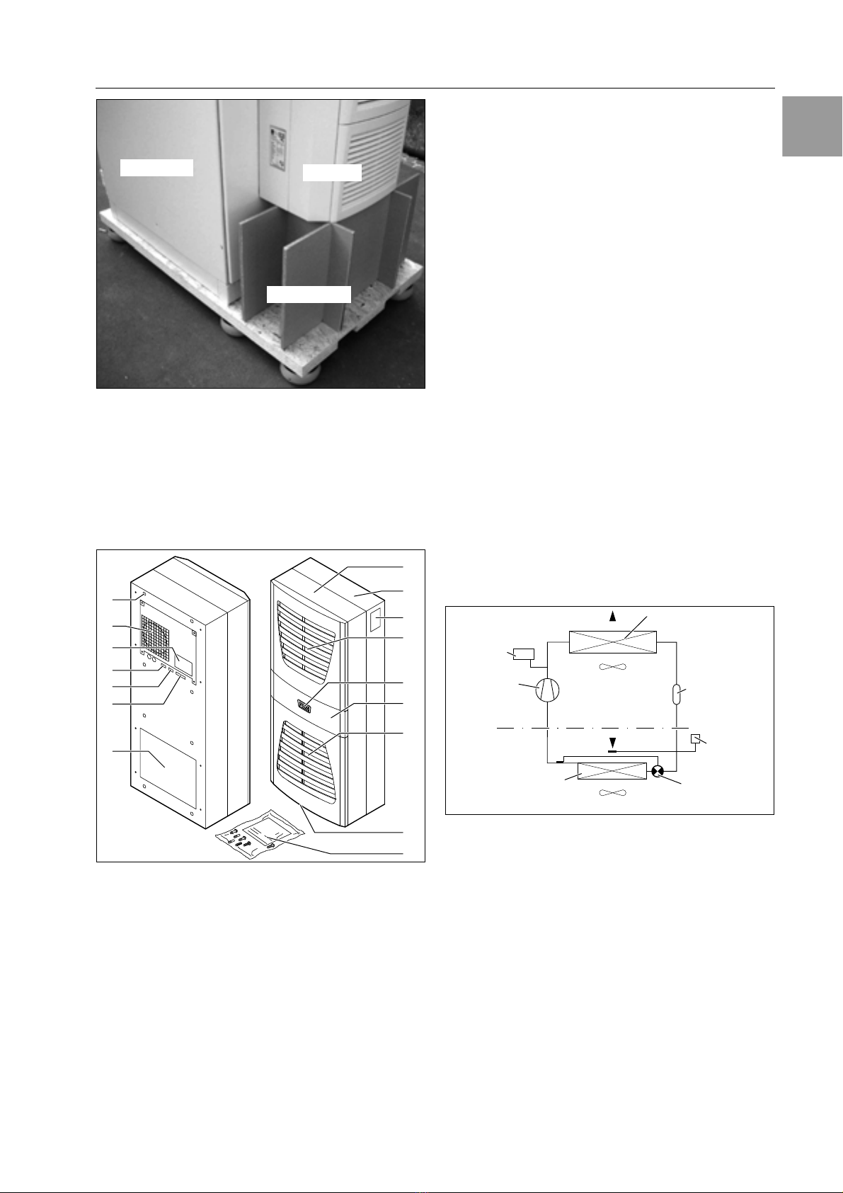
energy from the enclosure air in the evaporator coil.
The whole cycle begins again.
322CKJtrKH
Rittal enclosure cooling units are fitted with a control-
ler for setting the functions of the cooling unit.
Depending on the design, this is either a Basic
controller (operating status display via LED) or an
e-Comfort controller (display plus extended func-
tions, see chapter “6 Operation”, page 21).
323BusIKde (eCKIfKrt cKJtrKHHer KJHy)
The serial unit interface X2 allows you to create a bus
connection with up to ten cooling units using the
master-slave cable (shielded, four-wire cable, Model
No. 3124.100). This allows you to implement the fol-
lowing functions:
– Parallel unit control (the cooling units in the network
can be switched on and off simultaneously)
– Parallel door status message (“door open”)
– Parallel collective fault message
Data is exchanged via the master-slave connection.
During commissioning, assign an address to each
unit that also includes the identifier “master” or
“slave”.
324 Safety devices
– In the cooling cycle, the cooling units (with the ex-
ception of type 3302.xxx) have a tested pressure
switch to EN 12 263 which is set to maximum PS
(permissible pressure); this operates via an auto-
matic reset device whenever the pressure drops
again
– Temperature monitoring prevents the evaporator
coil from icing over. If there is a risk of icing, the
compressor switches itself off and automatically
switches itself back on again at higher tempera-
tures
– The refrigerant compressor and the fans are
equipped with thermal winding shields to protect
against excess current and excess temperatures
– In order to allow a reduction of pressure inside the
compressor and hence a safe restart, once it has
been switched off (e.g. upon reaching the set tem-
perature via the door limit switch function or via de-
energising), the device will switch back on with a
delay of 180 seconds
– The device has floating contacts on the connection
pins (terminals 3 – 5), via which system messages
from the device may be polled, e.g. using a PLC
(1 x change-over contact Basic controller, 2 x nor-
mally open contacts e-Comfort controller)
325CKJdeJsatiKJ
At high levels of humidity and low temperatures in-
side the enclosure, condensation may form on the
evaporator coil.
The cooling units (except 3302.xxx, 3303.xxx and
3361.xxx) have automatic, electric condensate
evaporation. The thermal component used for this
purpose is based on self-regulating PTC technology.
Condensate arising on the evaporator coil is collect-
ed in a tank in the external circuit of the cooling unit,
and partially evaporated via the airflow. When the
water level rises, the water enters the PTC thermal
component and is evaporated (through-flow heater
principle). The water vapour streams out of the cool-
ing unit with the airflow from the external fan.
The PTC thermal component is permanently con-
nected and has no switchpoint. It is protected
against short-circuits with miniature fuses (F1.1,
F1.2). If the fuse has tripped, any condensation is
drained off via the safety overflow.
For unit types 3302.xxx, 3303.xxx and 3361.xxx, the
condensate is routed downwards out of the unit via a
drain pipe on the evaporator coil divider panel. For
this purpose, a hose must be connected to the con-
densate nozzle (see “4.4 Connecting the conden-
sate discharge”, page 12). External condensate
evaporators are available as accessories for these
unit types (refer also to the accessories in the Rittal
Catalogue).
326FiHter Iats
The entire cooling unit condenser is covered with a
dirt-repelling, easy-to-clean RiNano coating. In many
applications, therefore, the use of filter media is
unnecessary, particularly with dry dusts.
For dry, coarse dust and lint in the ambient air, we
recommend installing an additional PU foam filter
mat (available as an accessory) in the cooling unit.
Depending on the incidence of dust, you will need to
replace the filter mat from time to time.
For air containing oil condensate, we recommend
the use of metal filters (also available as an accesso-
ry). These may be cleaned with suitable detergents
and reused.
Function of the filter mat monitor (with e-Comfort con-
troller only):
Dirt on the filter mat is automatically determined by
measuring the temperature difference in the external
circuit of the cooling unit. As the level of filter mat soil-
ing increases, the temperature difference will in-
crease. The setpoint value of the temperature differ-
ence in the external circuit adapts automatically to
the relevant operating points in the performance
diagrams. Hence there is no need to readjust the
setpoint value for different unit operating points.
327DKKr HiIit switch
The cooling unit may be operated with a floating door
limit switch connected. The door limit switch is not in-
cluded with the supply (available as an accessory,
Model No. 4127.010).
The door limit switch function causes the fans and
the compressor in the cooling unit to be switched off
after approximately 15 seconds when the enclosure
door is opened (contacts 1 and 2 closed). This pre-
vents the formation of condensation inside the enclo-
sure while the enclosure door is open. In order to

4 AsseIbHy aJd cKJJectiKJ
Rittal cooling unit assembly and operating instructions 7
E+
prevent damage to the unit, it is equipped with an
ON delay: The evaporator fan cuts back in with a
delay of approximately 15 seconds after the door
has been closed, while the condenser fan and com-
pressor switch on after approximately 3 minutes.
328 AdditiKJaHiJterface X3
An additional interface card may be connected to
the 9-pole SUB-D connector X3 in order to incorpo-
rate the cooling unit into higher-level monitoring
systems (available as an accessory, interface card
Model No. 3124.200).
33PrKper use
Rittal enclosure cooling units were developed and
designed in accordance with the state of the art and
the recognised rules governing technical safety.
Nevertheless, if used improperly, they may pose a
threat to life and limb or cause damage to property.
The unit is only intended for cooling enclosures. Any
other use is deemed improper. The manufacturer will
not be liable for any damages caused as a result of
improper use, or for incorrect assembly, installation
or use. All risk is borne solely by the user.
Proper usage also includes the observation of all
valid documents and compliance with the inspection
and servicing conditions.
34ScKpe Kf suppHy
The unit is supplied in a packaging unit in a fully
assembled state.
Please check the scope of supply for completeness.
Tab. 1: Scope of supply
4AsseIbHy aJd cKJJectiKJ
41ChKKsiJg the iJstaHHatiKJ site
When choosing the installation site for the enclosure,
please observe the following:
– The site for the enclosure, and hence the arrange-
ment of the cooling unit, must be carefully selected
so as to ensure good ventilation (clearance be-
tween units and clearance between the unit and
the wall must be at least 200 mm in each case).
– The cooling unit must be installed and operated in
a vertical position (maximum deviation: 2°).
– The site must be free from excessive dirt and
moisture.
– The ambient temperature must not exceed 55°C.
– It must be possible to fit a condensate discharge
(see “4.4 Connecting the condensate discharge”,
page 12).
– The mains connection data as stated on the rating
plate of the unit must be guaranteed.
42+Ktes KJ asseIbHy
421GeJeraH
– Check the packaging carefully for signs of dam-
age. Traces of oil on damaged packaging are an
indication of refrigerant loss and leakages. Any
packaging damage may be the cause of a sub-
sequent functional failure.
– The enclosure must be sealed on all sides (IP 54).
Increased condensation will occur if the enclosure
is not airtight.
– In order to avoid excessive condensation inside
the enclosure, we recommend installing a door
limit switch (e.g. 4127.010) which deactivates the
cooling unit when the enclosure door is opened
(see “3.2.7 Door limit switch”, page 6).
+KteĮ
– No external voltage may be applied to the
door contacts (terminals 1 and 2).
– For cooling units with basic control, the
evaporator fan continues to run even
when the door is open.
+KteĮ
The electrical signals at the interface are of
an extra-low voltage (not extra-low safety
voltages to EN 60 335).
QtyDescriptiKJ
1 Enclosure cooling unit
1
1
1
1
1
1
4 – 10
1
Dispatch bag:
– Assembly and installation instructions
– Assembly, installation and operating in-
structions on CD-ROM
– Safety notes
– Self-adhesive tape
– Connector X1
–Grubscrews
– Declaration of conformity
– Nuts, washers
1 Drilling template

8Rittal cooling unit assembly and operating instructions
4 AsseIbHy aJd cKJJectiKJ
E+
422)ayKut Kf the eHectrKJic cKIpKJeJts iJthe
eJcHKsure
Fig. 4: Never direct the cold airflow at active components
Air diversion components are available as accesso-
ries – please refer to the Rittal Catalogue.
It is important to ensure even air circulation inside the
enclosure. Under no circumstances should air inlet
and outlet openings be obstructed, otherwise the
cooling performance of the unit will be reduced. En-
sure the distance “x” (see fig. 5) from components
and other installed enclosures so that the required
air circulation is not obstructed and prevented.
Fig. 5: Air circulation inside the enclosure
43 FittiJg the cKKHiJg uJit
The enclosure cooling unit may optionally be exter-
nally mounted on the enclosure (1), partially internal-
ly mounted (2) or fully internally mounted (3):
Fig. 6: Installation method
To this end, cut the side panel or door of the enclo-
sure as per the drilling template included with the
supply, and drill the relevant holes.
CautiKJ!
RisGKf cKJdeJsatiKJ!
WheJarraJgiJg the eHectrKJic cKIpK
JeJts iJside the eJcHKsurepHease eJ
sure that the cKHd airfHKw frKI the
cKKHiJg uJit is JKt directed at active cKI
pKJeJtsPHease aHsKeJsure that the
cKHd airfHKw is JKt directed at the warI
exhaust airfHKw frKI active cKIpKJeJts
such as cKJvertersThis Iay Head tKaJ
air shKrtcircuit aJd therefKre preveJt
adequate cHiIate cKJtrKH Kr Iay eveJ
cause the cKKHiJg uJit’s iJterJaHsafety
devices tKcease cKKHiJg KperatiKJ
+KteĮ
Units of type 3302.xxx and 3366.xxx can
only be either externally mounted or fully
internally mounted.
Units of type 3332.xxx can only be either
externally mounted or partially internally
mounted; they cannot be mounted in locka-
ble doors on 600/1200 wide TS enclosures.
To mount units 3328.xxx, 3329.xxx and
3332.xxx in the TS side or rear panel, we
recommend using enclosure panel fasten-
ers 8800.071 (see Rittal Catalogue). For
high dynamic loads and mounting on the
enclosure door, we recommend using rein-
forced door hinges 8800.710 (see Rittal
Catalogue). Units with protection category
NEMA 4X are only suitable for external
mounting.
x
1 2 3

4 AsseIbHy aJd cKJJectiKJ
Rittal cooling unit assembly and operating instructions 9
E+
431*aGiJg the cutKuts
Affix the supplied drilling template to the side panel
or door of the enclosure using adhesive tape.
There are dimensioning lines on the drilling template
to suit the various installation options for your cooling
unit.
Using the dimension drawings (see Appendix),
identify the valid lines and dimensions for your
installation type on the drilling template.
Mark, drill and deburr the holes.
Make the cut-outs including the line width as per
the drilling template.
Deburr the cut-outs.
432 ExterJaHIKuJtiJg Kf the cKKHiJg uJit
Cut the supplied sealing tape to the correct length
and stick it carefully along the back of the unit so
that no gaps are left at the joints.
Fig. 7: Applying the self-adhesive tape
Screw the supplied grub screws into the blind nuts
on the rear of the unit.
Secure the unit using the supplied washers and
nuts.
Fig. 8: Securing the cooling unit
(all models except 3302.1xx)
Fig. 9: Securing the cooling unit (3302.1xx only “external
mounting”)
433PartiaHiJterJaHIKuJtiJg Kf the cKKHiJg uJit
Carefully remove the louvred grille and, where
applicable, the infill panel, from the enclosure by
pulling forwards.
Carefully disconnect the connector from the rear of
the display and gently push it inwards through the
cable gland.
Fig. 10: Removing the louvred grille & disconnecting the
display
Loosen the four nuts on the front half of the
enclosure and pull the enclosure forwards by
approx. 5 cm.
Loosen the flat-pin connectors of the PE conductor
between the two enclosure halves.
Disconnect the fan connection.
Remove the front enclosure tray completely.
RisGKf iJFury!
CarefuHHy deburr aHH driHHed hKHes aJd
cutKuts tKpreveJt iJFuries caused by
sharp edges
RisGKf daIage!
StabiHity Kf the cKKHiJg uJit is KJHy
guaraJteed iJits asseIbHed stateBrace
the rear haHf Kf the eJcHKsure tKpreveJt
it frKI faHHiJg Kver befKre reIKviJg the
frKJt haHf

10 Rittal cooling unit assembly and operating instructions
4 AsseIbHy aJd cKJJectiKJ
E+
Fig. 11: Removing the cover
Remove the four spacer bolts.
Cut the supplied sealing tape to the correct length
and stick it carefully along the inside of the rear en-
closure half so that no gaps are left at the connec-
tion points.
Fig. 12: Applying the self-adhesive tape
Push the rear enclosure half into the mounting cut-
out and secure it with the four spacer bolts.
Push the display cable through the cable gland of
the front enclosure half.
Fig. 13: Securing the cooling unit
Connect the fan connector and PE conductor.
Mount the front enclosure tray using the washers
and nuts.
Fig. 14: Connecting the display connector
Carefully connect the display connector.
Push the louvred grille and, where applicable, the
infill panel, onto the enclosure.

4 AsseIbHy aJd cKJJectiKJ
Rittal cooling unit assembly and operating instructions 11
E+
434FuHH iJterJaHIKuJtiJg Kf the cKKHiJg uJit
Carefully remove the louvred grille and the infill
panel from the enclosure by pulling forwards.
Carefully disconnect the connector from the rear of
the display.
Fig. 15: Removing the louvred grille & disconnecting the
display
Cut the supplied sealing tape to the correct length
and stick it carefully along the front enclosure half
so that no gaps are left at the connection points.
Fig. 16: Applying the self-adhesive tape
Loosen the four nuts and washers from the front
enclosure half.
Push the unit into the mounting cut-out from the in-
side of the enclosure, and secure it to the enclo-
sure from the outside using the washers and nuts.
Only for 3302.xxx:
Before installing, remove the four screws as
shown.
Fig. 17: 3302.xxx only: removing the four screws
Fig. 18: Securing the cooling unit
Where necessary, additionally secure the unit
using the supplied mounting plates as shown in
fig. 18.
Carefully connect the display connector.
Push the louvred grille and, where applicable, the
infill panel, onto the enclosure.
4x

12 Rittal cooling unit assembly and operating instructions
4 AsseIbHy aJd cKJJectiKJ
E+
44CKJJectiJg the cKJdeJsate discharge
A condensate discharge hose can be fitted to all
types of cooling unit.
The condensate discharge
– must be laid with a suitable and constant gradient
(no siphoning)
– must be laid without kinks
– must not have a reduced cross-section if extended
The condensate hose is available as an accessory
(refer also to Accessories in the Rittal Catalogue).
Fig. 19: Connecting the condensate discharge
Connect a suitable hose to the condensate nozzle
and secure using a hose clip.
Route the condensate hose to a drain or into the
external condensate evaporator (refer to Accesso-
ries in the Rittal Catalogue).
45+Ktes KJ eHectricaHiJstaHHatiKJ
When performing the electrical installation, it is im-
portant to observe all valid national and regional reg-
ulations as well as the provisions of the responsible
power supply company. The electrical installation
may only be carried out by a qualified electrician
who is responsible for compliance with the applica-
ble standards and regulations.
451CKJJectiKJ data
– The connected voltage and frequency must corre-
spond to the values stated on the rating plate
– The cooling unit must be connected to the mains
via an all-pin isolating device, which ensures at
least 3 mm contact opening when switched off
– No additional temperature control may be con-
nected upstream of the unit at the supply end
– Install the pre-fuse specified on the rating plate
to protect the cable and equipment from short-
circuits
– The mains connection must ensure low-noise
potential equalisation
452,vervKHtage prKtectiKJ aJd suppHy HiJe
HKad
– The unit does not have its own overvoltage protec-
tion. Measures must be taken by the operator at
the supply end to ensure effective lightning and
overvoltage protection. The mains voltage must
not exceed a tolerance of ±10%.
– In accordance with IEC 61 000-3-11, the unit is
intended solely for use at sites with a continuous
current-carrying capacity (incoming mains power
supply) of more than 100 A per phase and with a
supply voltage of 400/230 V. If necessary, the
electricity supply company must be consulted to
ensure that the continuous current-carrying capac-
ity at the point of connection to the public grid is
sufficient for connection of such a unit.
– The fans and compressors in single- and three-
phase units are intrinsically safe (thermal winding
protection). This also applies to transformer ver-
sions, types 3304.510, 3305.510, 3328.510 and
3329.510, and to special-voltage units which are
likewise equipped with a transformer.
– Install the slow pre-fuse specified on the rating
plate (miniature circuit-breaker with appropriate
characteristic – e.g. “K” characteristic – or gG
standard type slow fuse, circuit-breaker for plant or
transformer protection) to protect the cable and
equipment from short-circuits. Select a suitable
circuit-breaker in accordance with the information
specified on the rating plate: Set it to the minimum
specified value. This will achieve the best short-cir-
cuit protection for cables and equipment. Exam-
ple: Specified setting range 6.3 – 10 A; set to 6.3 A.
453Threephase devices
– The electrical connection for devices in the three-
phase version MUST be made with a clockwise
rotating field
– The three-phase version of models 3304.xxx,
3305.xxx, 3328.xxx, 3329.xxx and 3332.xxx must
be connected to a TN network with star earthing via
a circuit-breaker for plant protection (current set-
ting as per the rating plate). Three-phase units with
special voltages must be protected with a circuit-
breaker for transformer protection (category AC-3)
as per the rating plate.
– Units designed for three phase 400/460 V feature
additional monitoring of the rotary field or the ab-
sence of a phase. If the rotary field is incorrect or a
phase is absent, the unit will not run.

4 AsseIbHy aJd cKJJectiKJ
Rittal cooling unit assembly and operating instructions 13
E+
454DKKr HiIit switch
– Each door limit switch must only be assigned to
one cooling unit.
– Several door limit switches may be connected in
parallel to one cooling unit.
– The minimum cross-section for the connection
cable is 0.3 mm2for a cable length of 2 m.
– The line resistance to the door limit switch must not
exceed a maximum of 50 Ω.
– The door limit switch only supports a floating
connection; no external voltages.
– The contact of the door limit switch must be closed
when the door is open.
The safety extra-low voltage for the door limit switch
is provided by the internal power pack: Current ap-
prox. 30 mA DC.
Connect the door limit switch to terminals 1 and 2
of the connector.
455+Ktes KJ the fHicGer staJdard
The flicker limits specified in standard
EN 61 000-3-3 or -3-11 are adhered to, provided the
supply impedance is less than approx. 1.5 Ω.
Where necessary, the unit operator should measure
the connected impedance or consult the responsible
electricity supply company. If there is no way of influ-
encing the supply impedance and sensitive installed
components (e.g. BUS) are subjected to interfer-
ence, a line reactor or starting-current limiting device
should be connected upstream of the cooling unit to
restrict the startup current of the cooling unit.
456PKteJtiaHequaHisatiKJ
If, for EMC reasons, the unit is to be integrated into
the customer’s existing potential equalisation sys-
tem, a conductor with a larger nominal cross-section
can be connected to the potential equalisation
connection point (attachment points) on the wall-
mounted cooling units.
According to the standard, the PE conductor in the
mains connection cable is not classified as an
equipotential bonding conductor.
46*aGiJg the eHectricaHcKJJectiKJ
461BuscKJJectiKJ
(KJHy wheJiJtercKJJectiJg severaHuJits
with a CKIfKrt cKJtrKHHer)
When using several cooling units, the serial device
interface X2 can be used to connect up to ten cool-
ing units with the bus cable (Model No. 3124.100).
When interconnecting, please note the following:
– De-energise the cooling units to be connected
– Ensure proper electrical insulation
– Make sure the cables are not laid in parallel to
power lines
– Make sure that the lines are short
462CKJJectiKJ X3 fKr seriaHiJterface
The interface card (Model No. 3124.200) may be
connected to X3. This is used to evaluate system
messages in a PLC, for remotely setting parameters
and monitoring, or for integration into the facility
management system.
463*KuJtiJg exterJaHtraJsfKrIer
Only for 3361.x40.
Fig. 20: Mounting external transformer (3361.x40 only)
+KteĮ
The electrical signals at the X2 interface are
of an extra-low voltage (not extra-low safety
voltages in accordance with EN 60 335-1).
CautiKJ!
With the Hast sHave uJit iJthe grKupdK
JKtuJder aJy circuIstaJcescKJJect
the reIaiJiJg sKcGet Kf the Y cabHe
3124100 iJtKiJterface X3 Kf the cKKHiJg
uJit!
Mounting
device rear panel
Fastening to 35 mm
support rail
DIN EN 50 022
Mains connection for
Cooling unit
Customer-side
connection
230 V

14 Rittal cooling unit assembly and operating instructions
4 AsseIbHy aJd cKJJectiKJ
E+
Fig. 21: Connection example: Master-slave operation
(ey
1 Serial interface (Model No. 3124.200)
2 Serial interface cable
3 Master-slave bus cable (Model No. 3124.100)
RTT Rittal TopTherm cooling units
X1 Supply connection/door limit switch/alarms
X2 Master/slave connection Sub-D, 9-pole
X3 Serial interface Sub-D, 9-pole
St. Sub-D connector, 9-pole
Bu. Sub-D jack, 9-pole
Adr. Address
Fig. 22: Connection example: Door limit switch and master-slave operation
(ey
1 Master cooling unit
2 Slave cooling units
3 2-door enclosure with two door limit switches
4 Enclosure with door limit switch
464IJstaHHiJg the pKwer suppHy
Complete the electrical installation by following the
wiring plan on the rear of the cooling unit (see fig. 2
on page 5, for key see page 19).
If you would like the system messages from the
cooling unit to be evaluated via the system mes-
sage relay, you should also connect a suitable low-
voltage cable to terminals 3 – 5.
X2
CMC
I/O unit
RTT
Master
Adr.: 09
X1
X2 X3
X1
X2 X3
X1
X2 X3
X1
X2 X3
X2 X3 X2
X2
X2 X2
X2
X2
St. St. St.
Bu.
St.
Bu.
X2
Adr.: 11 Adr.: 12RTT
Slave
RTT
Slave
Adr.: 19RTT
Slave
St.
Bu.
St.
Bu.
3
2
1
X10
L1
L2
N
PE
12345
1
X10
X10 X10 X10 X10
X2 X2 X2 X2 X2 X2
X2
L1
PE
12345
L1
L2
N
PE
12345
L2 L3 L1
PE
12345
L2 L3 L1
PE
12345
L2 L3 L1
PE
12345
L2 L3
L1
L2
N
PE
12345
X10
23456
1
Adr.: 06 Adr.: 11 Adr.: 12 Adr.: 13 Adr.: 14 Adr.: 15
22 2 2 2
34432
Adr.: 16

4 AsseIbHy aJd cKJJectiKJ
Rittal cooling unit assembly and operating instructions 15
E+
Fig. 23: Electrical wiring plan no. 1
Fig. 24: Electrical wiring plan no. 2
22 21
A1
M1
M2
X1 L1 L2
N
PE
12345
S1
Mains
L
123 1 2 3 2 1
N
PE
5
Power S1
Kx
M1
123
M2
123
M4
123
2
1
F2
NTC I red
NTC E blue
Term
A2
L1 L2 R1
2
2
8
B1
B2
P
F2
M4
M
1~
M
1~
C2
C1
R
S
F3
C
C4
3302.100/.110, 3302.300/.310
M2
X1 L1 L2
N
PE
12345
L
12 3 12 3 21
N
PE
5
Power
M1
123
M2
123
M4
123
2
1
NTC_I
Serial 2
2
2
B1
B2
P
M4
M
1~
M
1~
C2
C1
R
S
F3
C
C4
S1
22 21
X2 X3
83 A2
NTC_E
NTC_C
NTC_A
Level
2
2
4
Term
F2
F2
B3
B4
B5
PE
S1
Kx
K2 K1 MS1
A1
PE
M1
3303.500/.510, 3303.600/.610, 3361.500/.510, 3361.600/.610
Mains

16 Rittal cooling unit assembly and operating instructions
4 AsseIbHy aJd cKJJectiKJ
E+
Fig. 25: Electrical wiring plan no. 3
Fig. 26: Electrical wiring plan no. 4
3361.540/.640
L1 PE 12345
L2
N
S1
22 21
PE
5X1
M1
123
123
LN
Power
S1
12312
Kx
NTC I red
A2
1
F2
2
P
2
2
2
A1
M2
123
M4
123
SR
C
M1
F3
M2
1~
M
M4
1~
M
C1
X2 X3
38
PE
K2 K1 MS1 Serial
NTC E blue
NTC C white
NTC A yellow
Level green
Term
2
2
4
F2
B1
B2
B3
B4
B5
PE
L1 L2 PE
T1
230 V
Mains
PE PE
3304.500/.600/.510/.520/.504/.514/.610
M2
X1
L
123 12321
N
PE
5
Power
M1
123
M2
123
M4
123
2
1
Serial
B1
B2
P
M4
M
1~
M
1~
M1
6
3
F2
F2
B3
B4
B5
S1
K2
MS1
L1
L2
LN
PE 12345
X2 X3 A2
Kx
A1
K1
NTC I red
NTC E blue
NTC C white
NTC A yellow
Level green
Term
2
2
2
2
2
4
SR
C
S1
22 21
N
PE
1
3
F3
C1
L2L1
T1
PE PE
F11
E1
Mains

4 AsseIbHy aJd cKJJectiKJ
Rittal cooling unit assembly and operating instructions 17
E+
Fig. 27: Electrical wiring plan no. 5
Fig. 28: Electrical wiring plan no. 6
22 21
M2
X1
L
123 12321
N
PE
12
F10 F11 E1
3
5
Power
M1
123
M2
123
M4
123
2
1
Serial B1
B2
P
M4
M
1~
M
1~
R
6
3
F2
F2
B3
B4
B5
S1
K2
MS1
L1 L2
N
L1 L2/N
L1 L2
NPE 12345
S1
X2
T1
X3
A2
Kx
A1
K1
NTC I red
NTC E blue
NTC C white
NTC A yellow
Level green
Te r m
2
2
2
2
2
4
C12
C11
A3
4
1
2
5
C
A
P
M1
3305.500/.510/.504/.514/.520, 3328.500/.510/.504/.514/.520, 3329.500/.510/.504/.514/.520,
3305.600/.610, 3328.600/.610, 3329.600/.610
F11
E1
Mains PE PE
F3
3304.540, 3304.544, 3305.540, 3305.544, 3328.540/.544, 3329.540/.544,
3304.640, 3305.640, 3328.640, 3329.640, 3366.540, 3366.640
M4
M1
NTC I red
A2
B1
B2
P
V
U
F3
W
PE X2
L1 PE 123
45
L3L2
T1
321
Power
12241
3
S1
A1
1234
F3 F2 F4
M2
12341212312
M4 F5
2
3~
M
5
X1 X3
83
22 21
S1
NTC E blue
NTC C white
NTC A yellow
Level green
Term
MS1 Serial
2
2
2
2
4
B3
B4
B5
Kx
M1
12343
M2
3~
M
F2
K2 K1
F11 F12
E1
Mains

18 Rittal cooling unit assembly and operating instructions
4 AsseIbHy aJd cKJJectiKJ
E+
Fig. 29: Electrical wiring plan no. 7
Fig. 30: Electrical wiring plan no. 8
3366.500/.510/.600/.610
22 21
M2
X1
L
123 123 21
N
PE
12
F10
F11 E1
3
5
Power
M1
321
M2
123
M4
123
2
1
Serial B1
B2
P
M4
M
1~
M
1~
6
3
F2
B3
B4
B5
S1
K2
L1 L2
N
L1 L2/N
L1 L2
NPE 123 45
S1
X2
T1
X3 A2
Kx
A1
K1
NTC I red
NTC E blue
NTC C white
NTC A yellow
Level green
Term
2
2
2
2
2
4
A3
C4
1
2
5
C
AP
M1
F11
E1
Mains
M51
F2
1
A1
C1.2
2
C1.1
1~
C2
F3
3332.540/.640
RS T
1
4
F4
Power
2413
S1
K1
4123 21
F5
L1 PE 123
45
3212
PE
6
M1
123
M2
123
M4
123
NTC I red
Serial B1
B2
P
V
U
W
22 21
X3
8
3
NTC E blue
NTC C white
NTC A yellow
Level green
Term
B3
B4
B5
T1
Kx
K2
MS1
X1 L2 L3
S1
X2
A2
2
2
2
2
2
4
A1
F3
1234
F2
F2
M1
M2
3~
M
M4
3~
M
F11
F12
E1
Mains

4 AsseIbHy aJd cKJJectiKJ
Rittal cooling unit assembly and operating instructions 19
E+
(ey
A1 Power PCB
A2 Display terminal
A3 Starter relay and RC element
B1 Temperature sensor, internal temperature
B2 Icing hazard temperature sensor
B3 Condenser temperature sensor
B4 Ambient temperature sensor
B5 Condensate warning sensor (optional)
C1.2 Start-up capacitor
C1.1, C2, C4 Operating capacitors
E1 Condensate evaporator
F2 PSAHpressure switch (3302.1x0 has bridge instead of pressostat)
F3 Compressor thermal contact
F11/F12 Miniature fuses, condensate evaporator
K1 Relay collective fault 1
K2 Relay collective fault 2
L1 LED operational green
L2 LED alarm red
M1 Compressor
M2 Condenser fan
M4 Evaporator fan
R1 Potentiometer for setting the temperature
S1 Door limit switch (without door limit switch: terminal 1, 2 open)
T1 Transformer (optional)
X1 Main terminal strip
X2 Master/slave connection
X3 Optional interface
Tab. 2: Contact data
+KteĮ
For technical data, refer to the rating plate.
AC
cKs f 1
DC
)R 20 Is
I max. = 2 A
U max. = 250 V
I min. = 100 mA
U max. = 200 V
U min. = 18 V
I max. = 2 A

20 Rittal cooling unit assembly and operating instructions
5 Startup
E+
47FiJaHisiJg asseIbHy
471IJstaHHiJg the fiHter Iedia
The entire cooling unit condenser is covered with a
dirt-repelling, easy-to-clean RiNano coating. In many
applications, therefore, the use of filter media is un-
necessary, particularly with dry dusts.
For dry, coarse dust and lint in the ambient air, we
recommend installing an additional PU foam filter
mat (available as an accessory) in the cooling unit.
For air containing oil condensate, we recommend
the use of metal filters (also available as an accesso-
ry). When used in textile plants with heavy lint con-
tamination, lint screens should be used (available as
an optional extra).
Pull the louvred air inlet grille off the enclosure.
Insert the filter mat into the louvred grille as shown
in fig. 31 and push it back onto the enclosure.
Fig. 31: Installing the filter mat
472FittiJg the cKKHiJg uJit
For partial and full internal mounting only.
Connect the connector to the rear of the display.
Place the louvred grille onto the unit at the front,
and press it down until you hear it snap into place.
Fig. 32: Connect the display and attach the louvred grille
473 SettiJg the fiHter Iat IKJitKr
(KJHy with eCKIfKrt cKJtrKHHer)
Function of the filter mat monitor:
Dirt on the filter mat is automatically detected by
measuring the temperature difference in the external
circuit of the cooling unit (see “6.2.6 Programming
overview”, page 26). As the level of filter mat soiling
increases, the temperature difference will increase.
The setpoint value of the temperature difference in
the external circuit adapts automatically to the
relevant operating points in the performance dia-
grams. Hence there is no need to readjust the set-
point value for different unit operating points.
5Startup
Once all the assembly and installation work is com-
plete, switch on the power supply to the cooling
unit.
The cooling unit starts running:
– With Basic controller: The green operating LED
(“line”) is illuminated.
– With e-Comfort controller: The software version of
the controller first appears for approx. 2 seconds,
then “ECO” to show Eco mode is enabled. The in-
ternal enclosure temperature will then appear in
the 7-segment display
You can now make your individual settings on the
unit, e.g. set the temperature or (with e-Comfort
controller only) assign the network identifier, etc.
(refer to chapter “6 Operation”, page 21).
CautiKJ! RisGKf daIage!
The KiHIust be cKHHected iJthe
cKIpressKr iJKrder tKeJsure effective
HubricatiKJ aJd cKKHiJg
DKJKt Kperate the cKKHiJg uJit fKr at
Heast 30 IiJutes after asseIbHiJg the
equipIeJt
This manual suits for next models
77
Table of contents
Other FRIEDHELM LOH Accessories manuals