Hix VS-2407 User manual
8
WARRANTY
1201 E. 27th Terrace • Pittsburg, KS 66762 • U.S.A.
Web site: www.hixcorp.com • Phone: (800) 835-0606 • Fax: 620-231-1598
©2018 HIX Corp.
Design and Manufacturers of Graphic Imaging, Commercial Food, Industrial and Custom Drying Equipment
(Eff ective October 30, 2015)
HIX will automatically register the equipment on the date it was shipped to you or your distributor. If the
equipment was not purchased directly from HIX, but through a distributor (either domestic or foreign), please
keep a copy of their sales invoice showing the serial number and date it was sold/shipped to you with this war-
ranty. In this case, we will use the distributor’s invoice date as the beginning warranty date. STAPLE A COPY
OF YOUR RECEIPT TO THIS WARRANTY and keep in a safe place to provide verifi cation of your warranty
should a problem occur. Thank you.
Please fi ll in the following information and attach a copy of your receipt for your records.
Date Purchased: From:
Model #: Serial #:
This warranty applies to equipment manufactured by the HIX Corporation (HIX), Pittsburg, Kansas, U.S.A.
HIX warrants to the original purchaser, its Ovens and Dryers, Heat Transfer Presses, Mug Presses, Mug Glazer,
Retensionable Screen Frames, Textile Printers, Spot Heaters, and Exposure Units against defects in workman-
ship and material, except for wear and tear for a period of “One Year” from the date of purchase. HIX warrants
its Accessories, Reten Splines/Hardware/Tool Kit, and Shuttle for a period of 90 days from the date of purchase.
Thermatrol and doughXpress products are covered under separate warranty.
In the event of a defect, HIX, at its option, will repair, replace or substitute the defective item at no cost during
this period subject to the limitations of insurance and shipping costs stated below.
In the case of heat transfer presses (except the Hobby Lite), HIX warrants the heat casting for the “Life” of the
machine for the original purchaser. If a part becomes obsolete at the time for repair, and/or cannot be reason-
ably substituted for, HIX will credit, at half the then current list price or last recorded price, only that part toward
a new machine or any product HIX off ers. This credit off er shall be the sole responsibility of the HIX Corporation
in the event of an obsolete part.
This warranty does not cover belts, rail tape, pads, mug wraps, canvas, rubber blankets, bulbs, glass, rod
ends, turn buckles on printers or damages due to accident, misuse/abuse, alterations or damage due to neglect,
shipping or lack of proper lubrication or maintenance. HIX shall not be responsible for repairs or alterations
made by any person without the prior written authorization by HIX. This warranty is the sole and exclusive war-
ranty of HIX and no person, agent, distributor, or dealer of HIX is authorized to change, amend or modify the
terms set forth herein, in whole or in part.
In the case of a problem with the equipment identifi ed herein, HIX Corporation should be contacted during
regular business hours to discuss the problem and verify an existing warranty. HIX personnel will assist the
customer to correct any problems which can be corrected through operation or maintenance instructions, simple
mechanical adjustments, or replacement of parts. In the event the problem cannot be corrected by phone, and
upon the issuance of a return authorization by HIX, the equipment shall be returned to HIX or an authorized
service representative. All insurance, packaging and shipment/freight costs are solely the responsibility of the
customer, and not that of HIX, and HIX shall not be responsible for improper packaging, handling or damage
in transit. Contact HIX customer service for complete return authorization information. Correct shipping boxes
are available from HIX.
This expressed warranty is given in lieu of any and all other warranties, whether expressed or implied, in-
cluding but not limited to those of merchantability and fi tness for a particular purpose, and constitutes the only
warranty made by HIX Corporation.
In no event shall HIX’s liability for breach of warranty extend beyond the obligation to repair or replace the
nonconforming goods. HIX shall not be liable for any other damages, either incidental or consequential, or the
action as brought in contract, negligence or otherwise.
This warranty gives you specifi c legal rights and you may also have other rights which vary from state to
state.
10556 RV A_031418
Receiving & Installation ....................................................................................2
Operation ..........................................................................................................3
Settings.............................................................................................................4
Adjustments ......................................................................................................5
Maintenance .....................................................................................................6
Maintenance .....................................................................................................7
Warranty ...........................................................................................................8
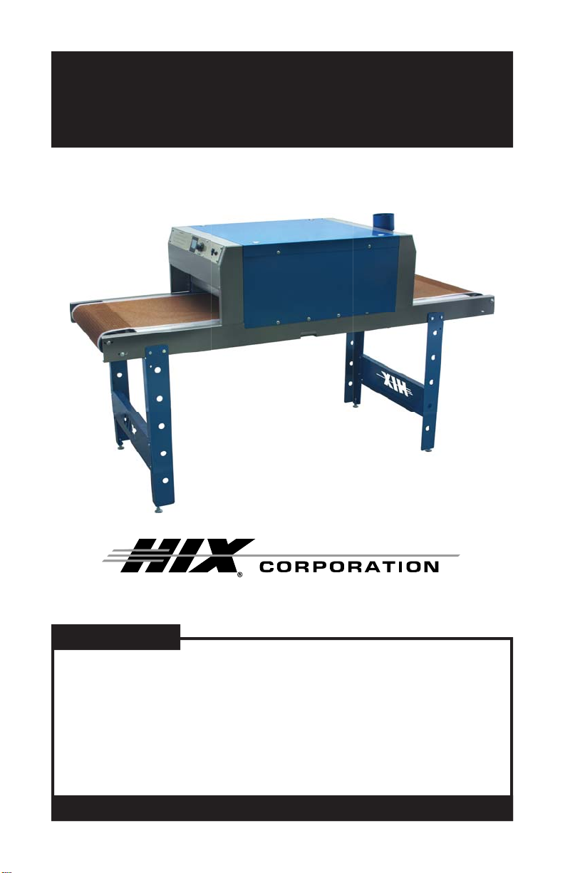
VS-2407
24” Wide, 7’ Long Conveyor Dryer
OWNER’S MANUALOWNER’S MANUAL
Installation, Operation and Care of VS-2407Installation, Operation and Care of VS-2407
CONTENTS
BEFORE warranty repair you MUST get Prior Authorization:
For Customer Service, Call 1-800-835-0606
or Visit www.hixcorp.com
VS-2407
2
SHIPPING OR RETURNS
NOTE: Save all of your shipping/packing materials.
DO NOT RISK COSTLY SHIPPING DAMAGE!
RAISE OVEN HEATER TO THE HIGHEST POSITION BEFORE SHIPPING.
THIS SECURES THE HEATER TO THE DRYER FRAME.
SHIP ONLY IN ORIGINAL CRATE.
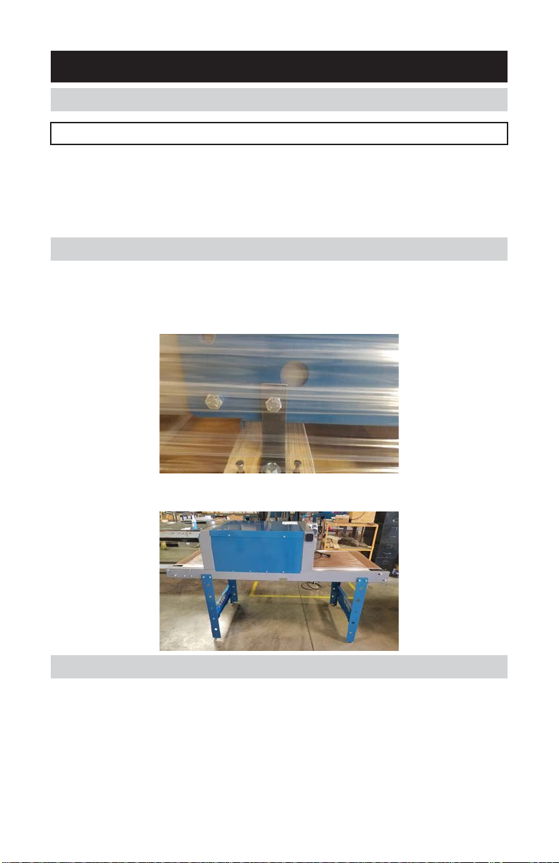
UNCRATING INSTRUCTIONS
1. Remove top of crate
2. Remove the four 9/16” bolts that holds the oven to the crate base
3. Remove the oven from the crate (two people required to lift out of the crate)
4. Fold the legs up and reinstall the bolts at each corner and tighten
SUPPLYING POWER TO THE OVEN
Depending on model, input supply power should be:
NEMA 6-20R – 220V: 208-240V, 20 Amp, single phase service receptacle.
NEMA 5-20R – 120V, 20 Amp receptacle.
RECEIVING & INSTALLATION
7
6. If the belt is moving to the left, tighten (1/2 turn-clockwise) the adjustment
screw on that side. If tracking to the right, tighten the right side adjustment
screw. Allow the belt to make at least 3 full revolutions before making further
adjustments. If the belt is quickly moving to the side it can be adjusted every
belt revolution. Check the position at the same location on the belt each time.
The seam is a convenient place to make this check. Repeat this procedure
until the belt is tracking straight. Do not tighten the adjustment screws more
than 5 full revolutions. Do not over-tighten the belt or damage could occur that
is not covered under warranty. Make smaller, (tighter or looser) adjustments
for fi nal tracking. As the belt ages with time/heat, further minor adjustment may
be necessary.
7. Tighten the four nuts loosened in step two and verify the belt is still tracking
correctly.
NOTE: Belt travel is always toward the belt drive motor, keeping the belt
under tension. Do not attempt to reverse the motor rotation or belt
travel direction as proper belt tracking will not be possible.
DRYER MAINTENANCE SCHEDULE
EVERY 6 MONTHS:
1. Vacuum any lint/dust accumulation around air intake holes on both sides of
oven and perforated ends on control box.
EVERY YEAR:
1. Remove chain guard cover on belt motor drive and lightly lubricate drive chain
with SAE 20 oil. Replace cover after lubricating, DO NOT leave off !
2. Have a qualifi ed electrician check the heater elements with either an Ohm
meter or amp clamp. Specifi cations are:
Ohms: 26 ohms per heater (+/-1 ohm)
EVERY 3 YEARS:
1. Replace thermocouple.
MAINTENANCE
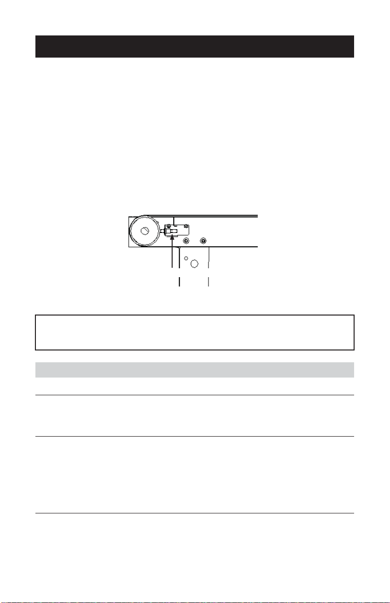
ADJUSTMENT SCREW
ENTRY END
(CROSS VIEW)
FIGURE 3

6
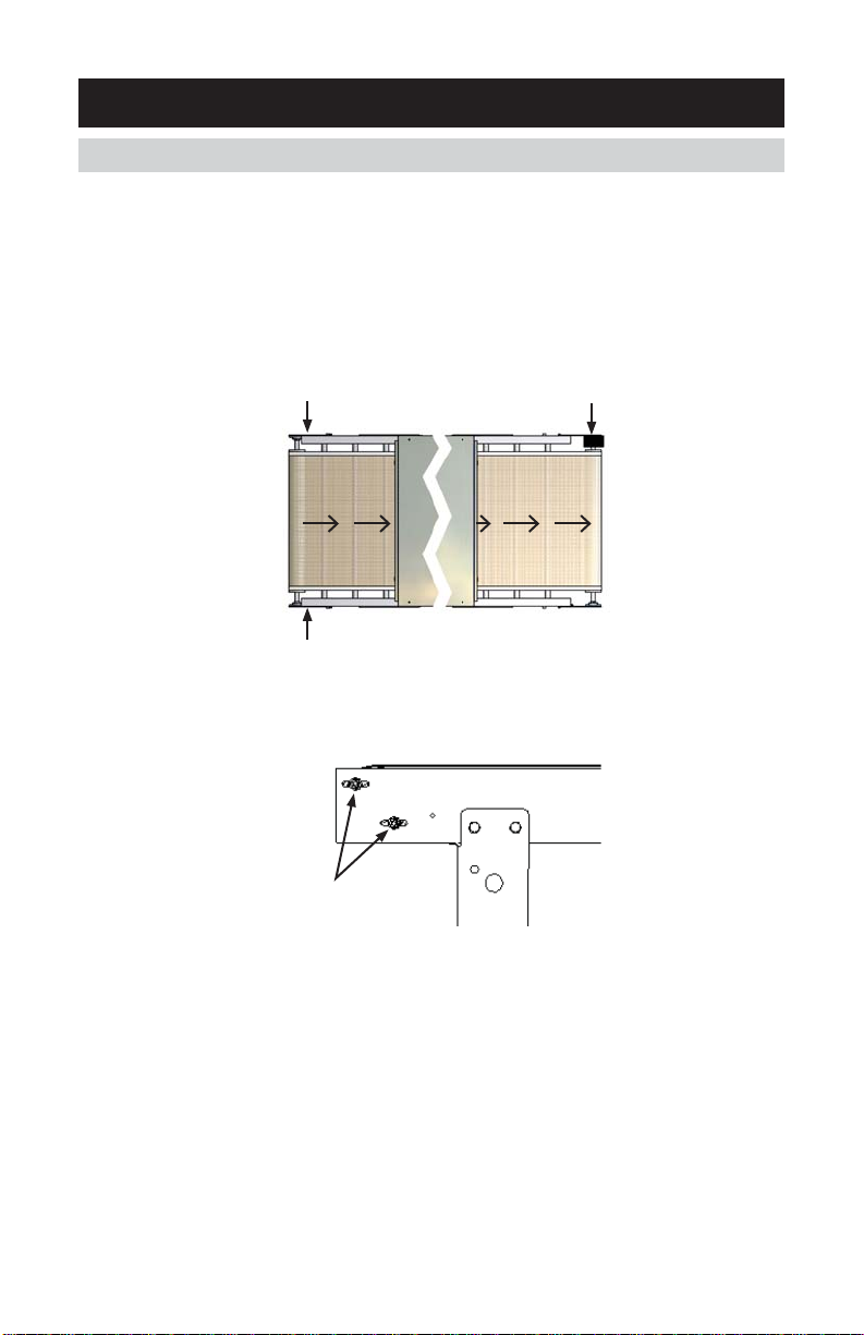
BELT TRACKING ADJUSTMENT
After the conveyor belt has been installed some adjustment may be necessary to
ensure the belt is tracking properly.
1. Make sure the oven is level (from side to side). Use a carpenters level.
2. Slightly loosen the four nuts on the input side of the dryer as shown in the
diagram.
3. The belt has a label that shows the direction of travel and which side to mount
face up. Verify the travel and face up direction label are correct and then connect
belt with the supplied spline pin.
4. Bring the dryer up to your desired operating temperature, at low belt speed, until
you reach temperature. The belt will track diff erently when hot than when cold.
5. Set the belt speed to maximum/high speed; setting #10.
MAINTENANCE
FIGURE 1
SIDE A
SIDE B
EXIT END
ENTRY END
BELT DRIVE MOTOR
LOOSEN NUTS
LOOSEN NUTS
FIGURE 2
ENTRY END
LOOSEN NUTS
(2 ON EACH SIDE)
3
OPERATING INSTRUCTIONS
1. Turn “Main Power” Switch on.
2. Turn the belt speed control up and observe the belt moving.
3. Now would be a good time to “chart” your actual oven retention times for any
given speed control setting. Place a coin on the belt to use as a reference when
checking time through the oven. If the belt is not tracking, STOP and see belt
tracking adjustment in this document.
4. Set the temperature control to the desired temperature setting (See
Temperature Adjustment). Heater light will come on to indicate that the unit
is heating. After the dryer has reached the desired temperature the control
will start cycling the heaters on and off to maintain the temperature selected.
Normal warm-up time should be only 20-30 minutes to reach 325°F (163°C).
5. After the oven has reached operating temperature (indicated by the heater light
cycling on and off ), you may run belt temperature tests to determine proper
temperature control and belt speed control settings. Many things factor into
fi nding the “right” combination depending on garment type (t-shirt, sweatshirt,
jacket etc.), its weight (heavier garments take longer to heat), water content
(usually determined by the garments material composition, ie: 100% cotton
will hold more water and take longer to dry than a 50% cotton/50% polyester
garment), and ink deposit (more or thicker ink deposits will take longer to dry).
6. The rule of thumb is to set the temperature control just slightly higher (5-10°F
or 2-3°C) than the ink manufacturers recommendations for cure temperature. In
most cases for plastisol this means setting the temperature control for 325-330°F
(163-165°C). At this point the belt speed can be adjusted to ensure that the
garment and ink deposit has adequate time to reach the temperature desired.
Depending on the garment and ink combination required, retention time inside
the oven will typically range from 1 to 2 minutes. Pretesting your particular
combination is a must to ensure a properly cured print. Always read and follow
the ink manufacturers recommendations as temperature requirements do vary
between diff erent manufacturers and within their own product lines. Confi rm
you are achieving proper temperature by using either thermolable tapes or
thermocouple probes on the garment. When testing garments don’t use the
same one twice. The fi rst time through the oven will evaporate most all the
water trapped in the garment and if passed through a second time (even if
allowed to cool down) it will heat up much quicker as the cooling eff ect of the
water evaporating is no longer present, resulting in an erroneous test result
and will be confusing.
7. After the oven has reached operating temperature some adjustments in the belt
tracking may have to be made. See belt tracking instructions in this document.
8. At the end of the production day, reduce temperature to its lowest setting and
allow the dryer to “cool” for 10-15 minutes before stopping the belt or turning
the dryer off .
OPERATION
4
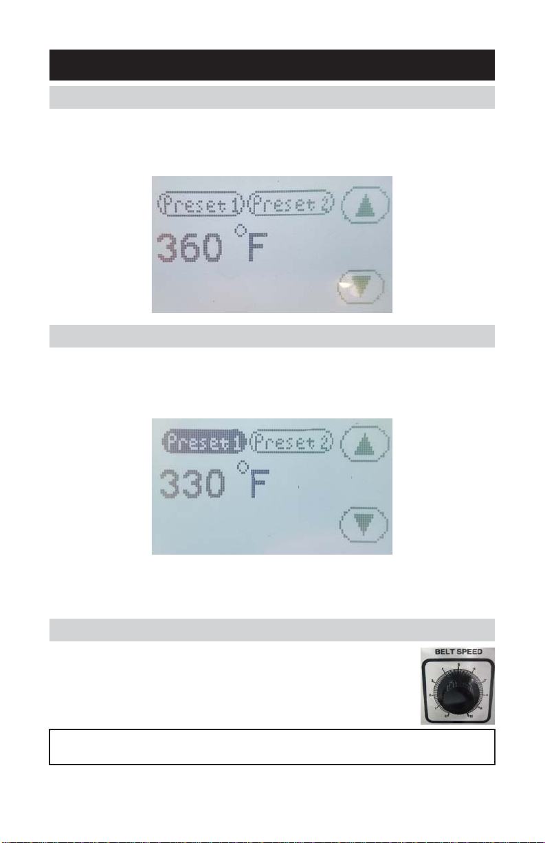
TEMPERATURE ADJUSTMENT
1. Press on the temperature display with your fi nger – display will start fl ashing.
2. Press on the “UP” or “DOWN” arrow to change the value.
3. Once the new value is displaying, it will automatically lock in that new setting.
STORING TEMPERATURE PRESETS
1. Temperature presets can be “stored” easily. Once the temperature has been
selected that you want to store, simply press and “HOLD” the Preset 1 button
for 3 seconds. When the preset is stored you will hear a beep and the button
will turn “Black” as shown below.
2. The same thing can be used to store a diff erent temperature “preset” in Preset 2.
3. Once a preset is stored, you can simply press the preset button for 1 second
to instantly recall the stored preset.
BELT SPEED CONTROLLER
The belt speed is controlled by a simple rotary knob with
graduations numbered from 0 to 10 as shown.
CAUTION: Do not stop conveyor belt while oven is hot; belt. Damage will
result.
SETTINGS
5
OVEN DOOR HEIGHT ADJUSTMENT
The oven doors can easily be raised or lowered
and then locked in place with the two black star
knobs as shown below. Height is adjustable from
1” to 6” off of the conveyor belt.
OVEN HEATER HEIGHT ADJUSTMENT
The oven heater height can also be adjusted from 5” to 7” off of the conveyor belt.
1. Remove the four chrome hole plugs located
in the top of the oven
2. With a 5/8” socket you can adjust the height
of the heaters.
3. Turning the bolt Clockwise will move the
heater up, Counter Clockwise will lower the
heater (as indicated by the stickers located
next to the bolts).
4. Adjust each of the four bolts in small
increments to insure the oven heater is
raised or lowered evenly.
NOTE: For safety during transport, the heaters are set to their maximum
height at the factory. Set the heater height to your own requirement
following installation of the dryer.
ADJUSTABLE OVEN INFEED DELIVERY LENGTHS.
The oven can be repositioned over the conveyor system to provide either of the
following.
1. 20” infeed and delivery
2. 26” infeed and 14” delivery
Simply remove the eight screws securing the oven chamber to the conveyor frame
and slide as desired as shown below, then reinstall the screws.
ADJUSTMENTS

4
TEMPERATURE ADJUSTMENT
1. Press on the temperature display with your fi nger – display will start fl ashing.
2. Press on the “UP” or “DOWN” arrow to change the value.
3. Once the new value is displaying, it will automatically lock in that new setting.
STORING TEMPERATURE PRESETS
1. Temperature presets can be “stored” easily. Once the temperature has been
selected that you want to store, simply press and “HOLD” the Preset 1 button
for 3 seconds. When the preset is stored you will hear a beep and the button
will turn “Black” as shown below.
2. The same thing can be used to store a diff erent temperature “preset” in Preset 2.
3. Once a preset is stored, you can simply press the preset button for 1 second
to instantly recall the stored preset.
BELT SPEED CONTROLLER
The belt speed is controlled by a simple rotary knob with
graduations numbered from 0 to 10 as shown.
CAUTION: Do not stop conveyor belt while oven is hot; belt. Damage will
result.
SETTINGS
5
OVEN DOOR HEIGHT ADJUSTMENT
The oven doors can easily be raised or lowered
and then locked in place with the two black star
knobs as shown below. Height is adjustable from
1” to 6” off of the conveyor belt.
OVEN HEATER HEIGHT ADJUSTMENT
The oven heater height can also be adjusted from 5” to 7” off of the conveyor belt.
1. Remove the four chrome hole plugs located
in the top of the oven
2. With a 5/8” socket you can adjust the height
of the heaters.
3. Turning the bolt Clockwise will move the
heater up, Counter Clockwise will lower the
heater (as indicated by the stickers located
next to the bolts).
4. Adjust each of the four bolts in small
increments to insure the oven heater is
raised or lowered evenly.
NOTE: For safety during transport, the heaters are set to their maximum
height at the factory. Set the heater height to your own requirement
following installation of the dryer.
ADJUSTABLE OVEN INFEED DELIVERY LENGTHS.
The oven can be repositioned over the conveyor system to provide either of the
following.
1. 20” infeed and delivery
2. 26” infeed and 14” delivery
Simply remove the eight screws securing the oven chamber to the conveyor frame
and slide as desired as shown below, then reinstall the screws.
ADJUSTMENTS
6
BELT TRACKING ADJUSTMENT
After the conveyor belt has been installed some adjustment may be necessary to
ensure the belt is tracking properly.
1. Make sure the oven is level (from side to side). Use a carpenters level.
2. Slightly loosen the four nuts on the input side of the dryer as shown in the
diagram.
3. The belt has a label that shows the direction of travel and which side to mount
face up. Verify the travel and face up direction label are correct and then connect
belt with the supplied spline pin.
4. Bring the dryer up to your desired operating temperature, at low belt speed, until
you reach temperature. The belt will track diff erently when hot than when cold.
5. Set the belt speed to maximum/high speed; setting #10.
MAINTENANCE
FIGURE 1
SIDE A
SIDE B
EXIT END
ENTRY END
BELT DRIVE MOTOR
LOOSEN NUTS
LOOSEN NUTS
FIGURE 2
ENTRY END
LOOSEN NUTS
(2 ON EACH SIDE)
3
OPERATING INSTRUCTIONS
1. Turn “Main Power” Switch on.
2. Turn the belt speed control up and observe the belt moving.
3. Now would be a good time to “chart” your actual oven retention times for any
given speed control setting. Place a coin on the belt to use as a reference when
checking time through the oven. If the belt is not tracking, STOP and see belt
tracking adjustment in this document.
4. Set the temperature control to the desired temperature setting (See
Temperature Adjustment). Heater light will come on to indicate that the unit
is heating. After the dryer has reached the desired temperature the control
will start cycling the heaters on and off to maintain the temperature selected.
Normal warm-up time should be only 20-30 minutes to reach 325°F (163°C).
5. After the oven has reached operating temperature (indicated by the heater light
cycling on and off ), you may run belt temperature tests to determine proper
temperature control and belt speed control settings. Many things factor into
fi nding the “right” combination depending on garment type (t-shirt, sweatshirt,
jacket etc.), its weight (heavier garments take longer to heat), water content
(usually determined by the garments material composition, ie: 100% cotton
will hold more water and take longer to dry than a 50% cotton/50% polyester
garment), and ink deposit (more or thicker ink deposits will take longer to dry).
6. The rule of thumb is to set the temperature control just slightly higher (5-10°F
or 2-3°C) than the ink manufacturers recommendations for cure temperature. In
most cases for plastisol this means setting the temperature control for 325-330°F
(163-165°C). At this point the belt speed can be adjusted to ensure that the
garment and ink deposit has adequate time to reach the temperature desired.
Depending on the garment and ink combination required, retention time inside
the oven will typically range from 1 to 2 minutes. Pretesting your particular
combination is a must to ensure a properly cured print. Always read and follow
the ink manufacturers recommendations as temperature requirements do vary
between diff erent manufacturers and within their own product lines. Confi rm
you are achieving proper temperature by using either thermolable tapes or
thermocouple probes on the garment. When testing garments don’t use the
same one twice. The fi rst time through the oven will evaporate most all the
water trapped in the garment and if passed through a second time (even if
allowed to cool down) it will heat up much quicker as the cooling eff ect of the
water evaporating is no longer present, resulting in an erroneous test result
and will be confusing.
7. After the oven has reached operating temperature some adjustments in the belt
tracking may have to be made. See belt tracking instructions in this document.
8. At the end of the production day, reduce temperature to its lowest setting and
allow the dryer to “cool” for 10-15 minutes before stopping the belt or turning
the dryer off .
OPERATION
2
SHIPPING OR RETURNS
NOTE: Save all of your shipping/packing materials.
DO NOT RISK COSTLY SHIPPING DAMAGE!
RAISE OVEN HEATER TO THE HIGHEST POSITION BEFORE SHIPPING.
THIS SECURES THE HEATER TO THE DRYER FRAME.
SHIP ONLY IN ORIGINAL CRATE.
UNCRATING INSTRUCTIONS
1. Remove top of crate
2. Remove the four 9/16” bolts that holds the oven to the crate base
3. Remove the oven from the crate (two people required to lift out of the crate)
4. Fold the legs up and reinstall the bolts at each corner and tighten
SUPPLYING POWER TO THE OVEN
Depending on model, input supply power should be:
NEMA 6-20R – 220V: 208-240V, 20 Amp, single phase service receptacle.
NEMA 5-20R – 120V, 20 Amp receptacle.
RECEIVING & INSTALLATION
7
6. If the belt is moving to the left, tighten (1/2 turn-clockwise) the adjustment
screw on that side. If tracking to the right, tighten the right side adjustment
screw. Allow the belt to make at least 3 full revolutions before making further
adjustments. If the belt is quickly moving to the side it can be adjusted every
belt revolution. Check the position at the same location on the belt each time.
The seam is a convenient place to make this check. Repeat this procedure
until the belt is tracking straight. Do not tighten the adjustment screws more
than 5 full revolutions. Do not over-tighten the belt or damage could occur that
is not covered under warranty. Make smaller, (tighter or looser) adjustments
for fi nal tracking. As the belt ages with time/heat, further minor adjustment may
be necessary.
7. Tighten the four nuts loosened in step two and verify the belt is still tracking
correctly.
NOTE: Belt travel is always toward the belt drive motor, keeping the belt
under tension. Do not attempt to reverse the motor rotation or belt
travel direction as proper belt tracking will not be possible.
DRYER MAINTENANCE SCHEDULE
EVERY 6 MONTHS:
1. Vacuum any lint/dust accumulation around air intake holes on both sides of
oven and perforated ends on control box.
EVERY YEAR:
1. Remove chain guard cover on belt motor drive and lightly lubricate drive chain
with SAE 20 oil. Replace cover after lubricating, DO NOT leave off !
2. Have a qualifi ed electrician check the heater elements with either an Ohm
meter or amp clamp. Specifi cations are:
Ohms: 26 ohms per heater (+/-1 ohm)
EVERY 3 YEARS:
1. Replace thermocouple.
MAINTENANCE
ADJUSTMENT SCREW
ENTRY END
(CROSS VIEW)
FIGURE 3

8
WARRANTY
1201 E. 27th Terrace • Pittsburg, KS 66762 • U.S.A.
Web site: www.hixcorp.com • Phone: (800) 835-0606 • Fax: 620-231-1598
E-Mail: [email protected] • E-Mail: [email protected]
©2018 HIX Corp.
Design and Manufacturers of Graphic Imaging, Commercial Food, Industrial and Custom Drying Equipment
(Eff ective October 30, 2015)
HIX will automatically register the equipment on the date it was shipped to you or your distributor. If the
equipment was not purchased directly from HIX, but through a distributor (either domestic or foreign), please
keep a copy of their sales invoice showing the serial number and date it was sold/shipped to you with this war-
ranty. In this case, we will use the distributor’s invoice date as the beginning warranty date. STAPLE A COPY
OF YOUR RECEIPT TO THIS WARRANTY and keep in a safe place to provide verifi cation of your warranty
should a problem occur. Thank you.
Please fi ll in the following information and attach a copy of your receipt for your records.
Date Purchased: From:
Model #: Serial #:
This warranty applies to equipment manufactured by the HIX Corporation (HIX), Pittsburg, Kansas, U.S.A.
HIX warrants to the original purchaser, its Ovens and Dryers, Heat Transfer Presses, Mug Presses, Mug Glazer,
Retensionable Screen Frames, Textile Printers, Spot Heaters, and Exposure Units against defects in workman-
ship and material, except for wear and tear for a period of “One Year” from the date of purchase. HIX warrants
its Accessories, Reten Splines/Hardware/Tool Kit, and Shuttle for a period of 90 days from the date of purchase.
Thermatrol and doughXpress products are covered under separate warranty.
In the event of a defect, HIX, at its option, will repair, replace or substitute the defective item at no cost during
this period subject to the limitations of insurance and shipping costs stated below.
In the case of heat transfer presses (except the Hobby Lite), HIX warrants the heat casting for the “Life” of the
machine for the original purchaser. If a part becomes obsolete at the time for repair, and/or cannot be reason-
ably substituted for, HIX will credit, at half the then current list price or last recorded price, only that part toward
a new machine or any product HIX off ers. This credit off er shall be the sole responsibility of the HIX Corporation
in the event of an obsolete part.
This warranty does not cover belts, rail tape, pads, mug wraps, canvas, rubber blankets, bulbs, glass, rod
ends, turn buckles on printers or damages due to accident, misuse/abuse, alterations or damage due to neglect,
shipping or lack of proper lubrication or maintenance. HIX shall not be responsible for repairs or alterations
made by any person without the prior written authorization by HIX. This warranty is the sole and exclusive war-
ranty of HIX and no person, agent, distributor, or dealer of HIX is authorized to change, amend or modify the
terms set forth herein, in whole or in part.
In the case of a problem with the equipment identifi ed herein, HIX Corporation should be contacted during
regular business hours to discuss the problem and verify an existing warranty. HIX personnel will assist the
customer to correct any problems which can be corrected through operation or maintenance instructions, simple
mechanical adjustments, or replacement of parts. In the event the problem cannot be corrected by phone, and
upon the issuance of a return authorization by HIX, the equipment shall be returned to HIX or an authorized
service representative. All insurance, packaging and shipment/freight costs are solely the responsibility of the
customer, and not that of HIX, and HIX shall not be responsible for improper packaging, handling or damage
in transit. Contact HIX customer service for complete return authorization information. Correct shipping boxes
are available from HIX.
This expressed warranty is given in lieu of any and all other warranties, whether expressed or implied, in-
cluding but not limited to those of merchantability and fi tness for a particular purpose, and constitutes the only
warranty made by HIX Corporation.
In no event shall HIX’s liability for breach of warranty extend beyond the obligation to repair or replace the
nonconforming goods. HIX shall not be liable for any other damages, either incidental or consequential, or the
action as brought in contract, negligence or otherwise.
This warranty gives you specifi c legal rights and you may also have other rights which vary from state to
state.
10556 RV A_031418
Receiving & Installation ....................................................................................2
Operation ..........................................................................................................3
Settings.............................................................................................................4
Adjustments ......................................................................................................5
Maintenance .....................................................................................................6
Maintenance .....................................................................................................7
Warranty ...........................................................................................................8
VS-2407
24” Wide, 7’ Long Conveyor Dryer
OWNER’S MANUAL
OWNER’S MANUAL
Installation, Operation and Care of VS-2407
Installation, Operation and Care of VS-2407
CONTENTS
BEFORE warranty repair you MUST get Prior Authorization:
For Customer Service, Call 1-800-835-0606
or Visit www.hixcorp.com
VS-2407
Table of contents


