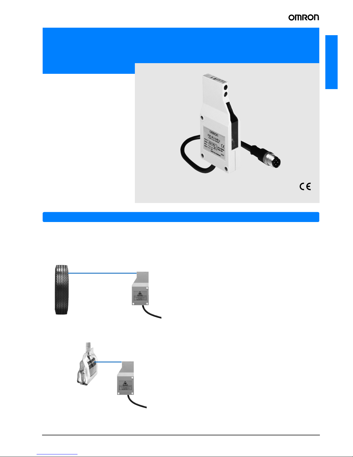
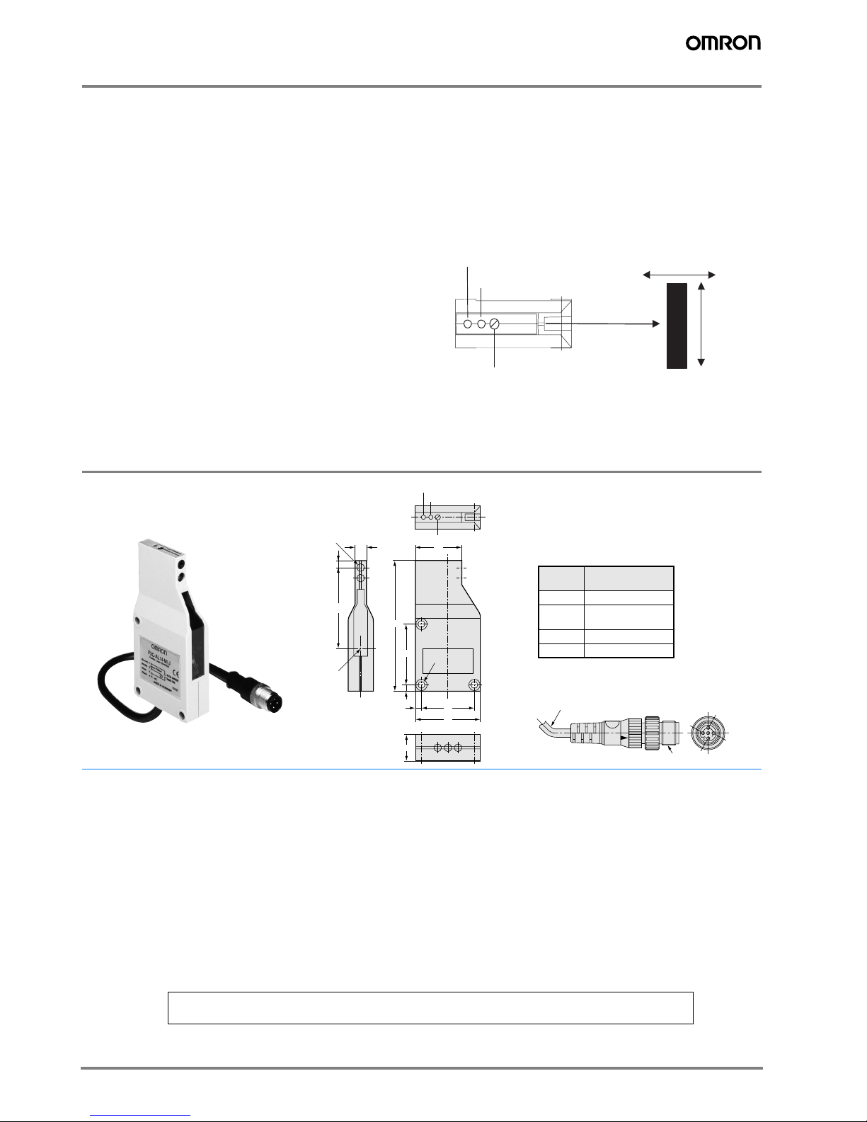
Omron F3C-AL User manual

F3C-AL
A-177F3C-AL
Distance setting laser photoelectric sensor
F3C-AL
• 700 mm max setting distance
• small visible Laser light spot for simple
adjustment
Features
Clear red spot ensures easy setting.
With its wide setting range 170 to 700 mm, F3C-AL is compat-
ible with standard conveyors. In the setting distance of 700
mm, the distance can be set easily with a 1.5x4 mm red spot.
Secure detection of shiny surface
Ensures stable detection of a 45-degree shiny surface. Detec-
tion of pouches, laminated packages or like minimizes setup
change time.
Unaffected by a shiny background.
Insensitive to shiny objects in the background, the Sensor can
be installed in any place.
Small Black/White error:
2% (Setting distance 300 mm),
8% max. (Setting distance 500 mm)
A little black/white error saves adjustment time during setup
change.
Full hysteresis detection range 0.5% max.
(for white paper)
6-turn adjuster ensures ease of adjustment.
700mm
170mm

A-178 Standard Photoelectric Sensors
Application
Ordering Information
Sensors
Accessories (Order Separately)
Shape Connection
method Sensing/Setting range Operating mode Model
NPN output PNP output
Pre-wired with
M12-connector
Light-ON/Dark-ON cable
connection selectable F3C-AL14-M1J F3C-AL44-M1J
Detection of the object
between 150 to 700 mm max.
on the conveyor.
F3C
The cup of yogurt
Detection of food being transferred
Since it is a reflection
type, a viewport is
OK with one place!
F3C
Wafer
Detection of wafers through view port
(Reflective model)
Red light
120 170
Setting range
120 to 700 mm
Sensing distance
700 mm
Mounting Brackets
Shape Model Quantity
E39-L40 1
Sensor I/O Connectors
Cable spec-
ifications Shape
Cable type
Model
Standard
cable
2 m
4 con-
ductors
XS2F-D421-D80-A
5 m XS2F-D421-G80-A
2 m XS2F-D422-D80-A
5 m XS2F-D422-G80-A
Robotcable
(for vibra-
tion resis-
tance)
2 m XS2F-D421-D80-R
5 m XS2F-D421-G80-R
2 m XS2F-D422-D80-R
5 m XS2F-D422-G80-R
Straight
t
yp
e
L type
Straight
type
L type

A-179F3C-AL
F3C-AL
Rating/Performance
Item Model F3C-AL14-M1J F3C-AL44-M1J
Sensing 120 to 700 mm (White paper 100 x 100 mm) (Setting distance 700 mm)
Setting distance range 170 to 700 mm (White paper, 90% remission, 100 x 100 mm)
170 to 560 mm (White paper, 6% remission, 100 x 100 mm)
Black-/white-error 20% max. (of setting distance, 90%/6% remission)
Spot Diameter 1.5 x 4 mm (Setting distance 700 mm)
Light source
Pulsed red light semiconductor laser
Class II: < 1mWeff. / 670 nm / 5% duty cycle
(Impulse time 60 µs, Period time: 1.2 ms)
Power supply voltage 10 to 30 VDC [ripple (p-p) 10% included]
Current consumption 30 mA max.
Control output
Load supply voltage 30 VDC max., load
current 150 mA max. (residual voltage: 2 V max.)
NPN open collector output type, Light-ON/Dark-ON
cable connection selectable
Load supply voltage 30 VDC max., load
current 150 mA max. (residual voltage: 2 V max.)
PNP open collector output type, Light-ON/Dark-ON
cable connection selectable
Protective circuits Reverse polarity protection, output short-circuit protection, mutual interference prevention
Response time Operation and reset: 10 ms max.
Sensitivity adjustment 6-turn adjuster
Ambient illuminance Incandescent lamp/Sunlight: 5,000 lux max.
Ambient temperature Operating: 0°C to 50°C, Storage: -25°C to 60°C (with no icing or condensation)
Ambient humidity Operating/Storage: 35% to 85%RH (with no condensation)
Insulation resistance 20 M min. at 500 VDC
Vibration resistance 10 to 55 Hz double amplitude 1.5 mm or 300 m/s2for 2 h in each of X, Y, Z directions
Shock resistance Destruction: 500 m/s2for 3 times each in X, Y, and Z directions
Protective structure IEC Standard IP40
Connection method M12 connector joint type (standard cable length 200 mm) / 4 x 0.34 mm² (PVC)
Weight (packed state) Approx. 80 g
Material Case ABS
Lens Acrylics (PMMA)
Accessories Adjusting screwdriver, Laser warning label, instruction manual

A-180 Standard Photoelectric Sensors
Characteristic data (typical)
Parallel operating range Black/White error Short distance characteristic chart
Hysteresis
4
3
2
1
0
-1
-2
-3
-4
100 200 300 400 500 600 700
Distance X (mm)
150mm
400mm 700mm
Distance Y (mm)
Setting distance (mm)
20
15
10
5
0150 200 300 400 500 600 700
Sensing object
White paper: reflectivity 90 %
Black paper: reflectivity 5 %
Black and white error (%)
800
700
600
500
400
300
200
100
0
90mm
50mm
185mm
70mm
White paper Black paper
Materi
a
Setting distance 700mm
170mm
Distance (mm)
Setting distance (mm)
3.0
2.0
1.0
0 100 200 300 400 500 600 700
Sensing object
White paper: reflectivity 90 %
Black paper: reflectivity 5 %
Black paper
White paper
Hysteresis (%)

A-181F3C-AL
F3C-AL
Output Circuit Diagram
NPN output
PNP output
Connectors (Sensor I/O connectors)
Model Operating status of
output transistor Timing chart Mode
selection Output circuit
F3C-AL14-M1J
Light ON
Connect
B
to
A
or dis-
connect
B
.
Dark ON
Connect
B
to
C
.
Model Operating status of
output transistor Timing chart Mode
selection Output circuit
F3C-AL44-M1J
Light ON
Connect
B
to
A
or dis-
connect
B
.
Dark ON
Connect
B
to
C
.
Incident
Interrupted
ON
OFF
ON
OFF
Operate
Reset
Light
indicator
(red)
(Between 1 and 4)
Output
transistor
Load
(Relay)
10 to 30 VDC
Main
circuit
Load
(Relay)
Operation selectable
150 mA
max.
Light
indicator
(red)
Stability
indicator
(green)
0V
ZD
1
4
3
2
Connector Pin Arrangement
3
1
24
Incident
Interrupted
ON
OFF
ON
OFF
Operate
Reset
Light
indicator
(red)
(Between 1 and 4)
Output
transistor
Load
(Relay)
10 to 30 VDC
Main
circuit
Load
(Relay)
Operation selectable
150 mA
max.
Light
indicator
(red)
Stability
indicator
(green)
0V
ZD
1
4
3
2
Connector Pin Arrangement
3
1
24
10 to 30 VDC
Incident
Interrupted
ON
OFF
ON
OFF
Operate
Reset
Light
indicator
(red)
(Between 3 and 4)
Output
transistor
Load
(Relay)
10 to 30 VDC
Main
circuit Load
(Relay)
Operation selectable
150 mA
max.
Light
indicator
(red)
Stability
indicator
(green)
0V
ZD
1
4
3
2
Connector Pin Arrangement
3
1
24
Incident
Interrupted
ON
OFF
ON
OFF
Operate
Reset
Light
indicator
(red)
(Between 3 and 4)
Output
transistor
Load
(Relay)
10 to 30 VDC
Main
circuit
1
4
3
2
Load
(Relay)
Operation selectable
150 mA
max.
Light
indicator
(red)
Stability
indicator
(green)
0V
ZD
Connector Pin Arrangement
3
1
24
Class Wire, outer Connector Application
For
DC
Brown APower supply (+V)
White BOperation switching
Blue CPower supply (0 V)
Black DOutput
Brown
White
Blue
Black
Terminal No. Cable core
wire jacket color
XS2F-D42
#
-D80-
#
XS2F-D42
#
-D80-
#
2
4
13
1
2
3
4

A-182 Standard Photoelectric Sensors
Sensitivity Adjustment
Special hints
Recommended adjustment
To assure stable working conditions the green stability LED should
be always turned on.
The green LED displays two stability conditions:
1. Output stable ON (red LED on)
2. Output stable OFF (red LED off)
Best performance can be achieved if the sensing object is located
closer than -10 % of the setting distance or the shiny background is
fixed +10 % behind the switching position.
Item Position A Position B and C Setting
Adjustment
procedure
Place the detected object at the de-
sired location and turn the LIGHT indi-
cator (red) lights. This is position A
Background object
Remove the detected object and turn
the adjustment knob clockwise until the
LIGHT indicator(red) lights. This is the
position B.
Then turn the adjustment knob coun-
terclockwise until the LIGHT indicator
(red) goes out. This is position C.
No Background object
The maximum adjustment setting is
used as position C.
Set the adjustment to halfway between
A and C. Confirm that the STAB indica-
tor (green) remains lit both with the de-
tected object present and not present.
If the STAB indicator does not remain
lit, review the detection method to en-
able stable operation.
Detecting
condition
Status of dis-
tance
setting
knob
Indicators
Photoelectric
sensor
Detected object
A
Photoelectric
sensor
Detected object
C
Background
object
B
A
B
C
A
C
OFF ON
STABILITY
(green) LIGHT
(red)
OFF OFF
STABILITY
(green) LIGHT
(red)
ON OFF
STABILITY
(green) LIGHT
(red)

A-183F3C-AL
F3C-AL
Precautions
Safety Precaution
Laser beam!
Laser protection class 2
Do not look into the laser beam.
Pay attention to the accident prevention regulations and the
laser protection class.
Visible laser emission!
Avoid any indirect or direct radiation of
reflected or emitted laser light!
Laser safety
The laser safeguards have been stipulated for laser equip-
ment in and outside Japan. The following gives brief descrip-
tion for use in Japan.
The JIS C6802 Standard stipulates safety preventives that
must be taken by the user according to the laser product
class. (The outline is given in the following table.)
User's Requirements
* 5 mW or less in the visible range
Classification of F3C
Handle laser equipment in accordance with the following pre-
cautions.
• Do not look into the beam.
• Do not disassemble the product. Doing so will release the
laser beam to wander around.
Please obtain or prepare the "Laser product safety standards"
on your own responsibility.
Labels related to laser
The following warning label is applied to the side face of the
photoelectric sensor.
For use in Japan, change the above label for the one that
meets the JIS Standards.
Handling Instructions
F3C radiates a visible-light laser. Do not look into it directly.
Use F3C so that the light path of the laser beam is terminated.
If there is a mirror-smooth reflector in the light path, confine
the beam away from the reflected light path. If F3C must be
used with the light path open, avoid placing the light path on
the eye level.
Design
Power Reset Time
The Photoelectric Sensor is ready to sense an object in 300
ms after power-on. Therefore, use it 300 ms after power-on. If
the load and Sensor are connected to different power sup-
plies, always switch on power for the Sensor first.
Wiring Considerations
Load short-circuit protection
• The F3C-AL has load short-circuit protection. If a load short-
circuit or like has occurred, the output turns OFF. Therefore,
recheck the wiring and switch power on again. This resets
the short-circuit protection circuit. Load short-circuit protec-
tion is activated when a current of 1.8 times or more of the
rated load current flows. When using an L load, use the one
the inrush current of which is less than 1.8 times of the rated
load current.
• Do not use the input power exceeding the rated voltage.
Doing so can cause damage.
• Do not shorten the load with the open collector output. Oth-
erwise, damage might be caused.
• Run the wiring of F3C separately from the high voltage and
power cables.
Class Class 1 Class 2 Class
3A
Class 3B Class 4
Item 3B* 3B
Using remote
interlock Not required
Connect the re-
mote interlock of
the laser beam to
the emergency
main interlock, the
interlock of the
room, or the inter-
lock of the door.
Key control Not required
Do not keep the
key in the lock
when the laser
beam is not used.
Beambreaker
or attenuator Not required
Used to protect
people from acci-
dental radiation by
the laser beam.
Warning sign Not required
Post a proper warning sign on
the door to the room where
laser beam equipment is in-
stalled.
Beam path Not re-
quired
The laser beam must be terminated and, as a rule,
must be enclosed. If the laser beam is exposed,
the vertical height of the beam must not be the
same as that of the eyes.
Mirror
reflection Not required
Appropriate optical elements
must be securely attached
and you must be able to con-
trol the optical elements dur-
ing laser radiation.
Eye protect Not required
Use eye protectors
except in special,
specified locations.
Protection
clothes Not required Wear protection clothes if exposure of
the skin to the laser beam may exceed
the MPE of the skin.
Training Not required The laser system must be operated by
only properly trained people.
Class 2
Correct Use
LASER LIGHT
DO NOT LOOK DIRECTLY INTO THE BEAM!
NOT EVEN THROUGH OPTICAL
INSTRUMENTS.
LASER PROTECTION CLASS 2
Pout < 1mW 670nm

A-184 Standard Photoelectric Sensors
• Avoid wiring them together or running them within the same
duct. Doing so may get them induced, causing a malfunc-
tion or damage.
• For extension of the cable, use a 0.3-mm2or more cable
and run it within 50 m.
Mounting
• Install the photoelectric sensor so that the sun, fluorescent
lamp, incandescent lamp or any other strong light will not
enter the directional angle range of the sensor.
• If Sensors are installed face-to-face, ensure that no optical
axes cross each other. Otherwise, mutual interference may
result.
• Use M4 screws to mount the unit.
• When mounting the case tighten it to the torque of 1.2 Nm
max.
Miscellaneous
Operating Environment
• Avoid using the Sensor in a strong disturbance light (e.g. la-
ser beam or arc welding beam) or strong electromagnetic
field.
• Depending on their material and/or shape, some objects
may not be detected or may be detected with low accuracy.
(Mirror-smooth material, transparent material, material of
extremely low reflectivity, object smaller than spot diameter)
Correct operation
The moving direction of the sensor or object should be prefer-
ably along the optical axis of the light beam. Lateral approach
is also possible. Movement from the top to the bottom or op-
posite can cause malfunction and should be avoided.
Dimensions (Unit: mm)
Accessories (Order Separately)
Mounting Brackets
H-5
Movement of object
Light beam
Sensing distance
adjustor
Red LED (light received)
Green LED (stability)
Sensors
F3C-AL14-M1J
F3C-AL44-M1J
18
4
Three,
4.2 dia.
4
37
42
8
4.7
(55)
Emitter
Receiver
90
45
32
Distance adjuster
Light indicator (red)
Stability indicator (green)
M12 x 1
1
3
2
4
inyl-insulated round cable of 4 dia.
4 cores conductorStandard length:
200 mm
Terminal No.
Specifications
1+V
2
L-ON/D-ON selectable
30V
4 Output
Note: Connection 1 to 2 is L-ON
Connection 2 to 3 is D-ON
Note. L-ON when 1-2 are connected
D-ON when 2-3 are connected
Termi-
nal No. Specifications
1+V
2L-ON/D-ON
selection
30V
4 Output
In the interest of product improvement, specifications are subject to change without notice.
ALL DIMENSIONS SHOWN ARE IN MILLIMETERS.
To convert millimeters into inches, multiply by 0.03937. To convert grams into ounces, multiply by 0.03527.
Cat. No. E510-E2-01-X
This manual suits for next models
2
Table of contents
Other Omron Accessories manuals

Omron
Omron F500 - User manual

Omron
Omron ZN-A Series User guide

Omron
Omron F3S-TGR-CL_B User manual

Omron
Omron Sti F3SJ-AM P Series User manual

Omron
Omron ZS-HLDS14AFT User manual

Omron
Omron E3K User manual

Omron
Omron B5WC User manual

Omron
Omron FZ3 Series User manual

Omron
Omron E3ZM-C - User manual

Omron
Omron E3F2-SUS - User manual

Omron
Omron E3Z-H User manual

Omron
Omron F3SJ-A series User manual

Omron
Omron E3G-L1 User manual

Omron
Omron E3M-V - User manual

Omron
Omron ZG2 Series User manual

Omron
Omron ZX-LDA11 Installation manual

Omron
Omron ZX-GT - User manual

Omron
Omron fh series Instructions for use

Omron
Omron E3X-NA - User manual

Omron
Omron ES1 N Series User manual