1 Application
Rittal cooling unit assembly and operating instructions page 3 of 27
1 Application
Enclosure cooling units are designed and built to dis-
sipate heat from enclosures by cooling the air inside
the enclosure and protecting temperature sensitive
components.
2 Technical data
See nameplate
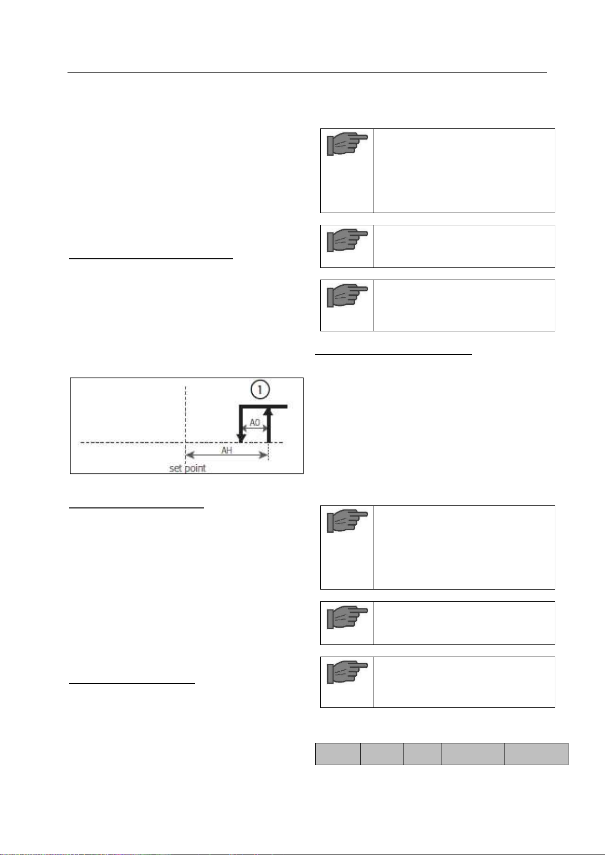
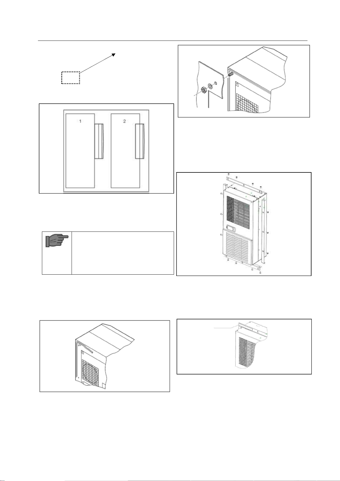
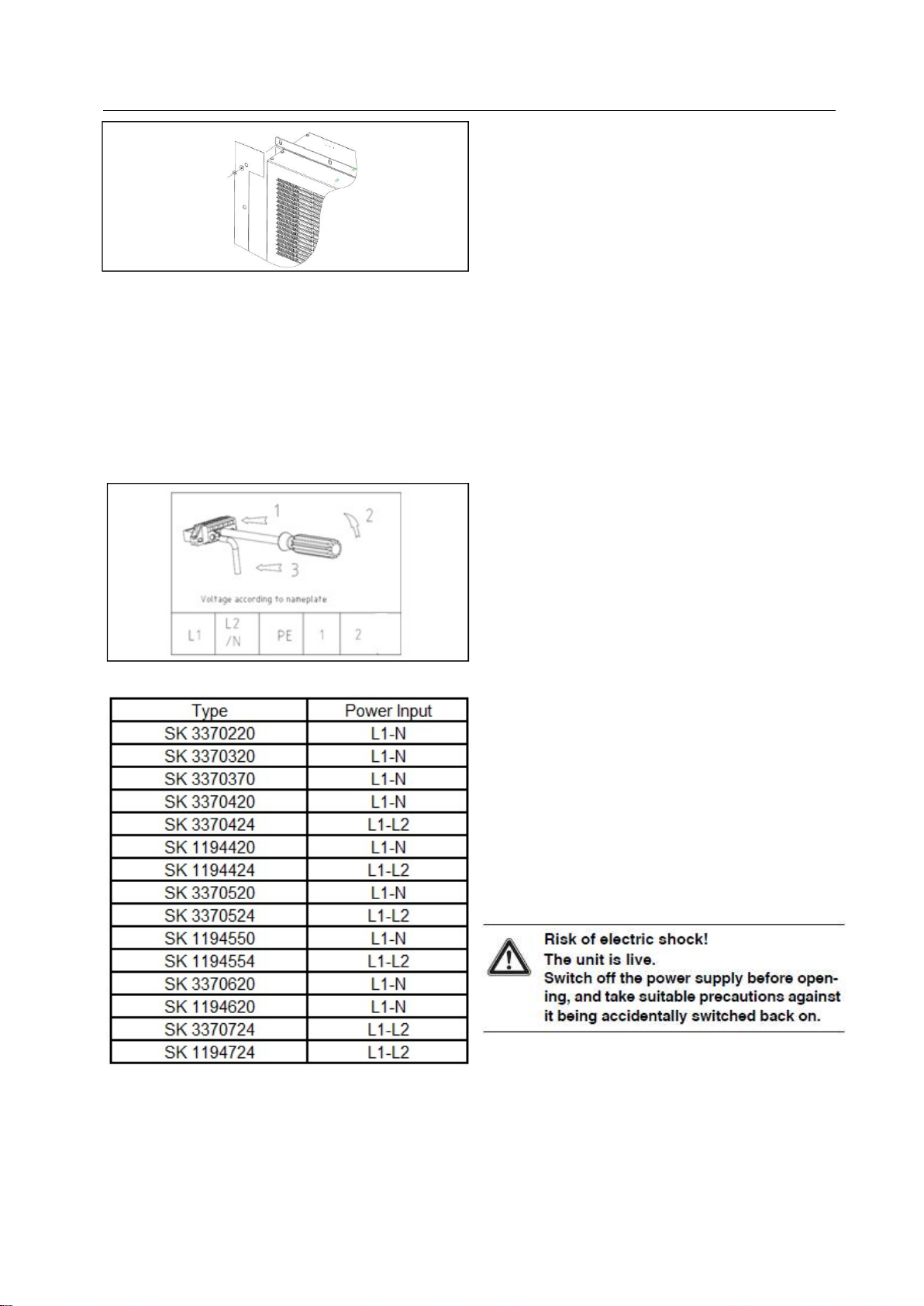
3 Assembly
The standard wall-mounted unit is suitable for exter-
nal mounting. Cut out the sections and drill according
to the drawing.
Cut the enclosed seals to the required length and at-
tach to the unit. Screw tapped pins into the blind nuts
on the rear of the unit. The unit is then to be secured
using washers and nuts
4 Safety notes
The following safety notices are to be observed in
their entirety for the correct use of the equipment:
To prevent the enclosure with the cooling unit fit-
ted tipping over, it is essential that this be bolted
to the floor.
A roller door is to be used to ensure problem free
opening and closing of the enclosure door.
A transportable enclosure with built-in cooling
unit may only be produced if an additional
transport anchorage to support the cooling unit is
used.
Prior to mounting, ensure that:
the site for the enclosure, and hence the arrange-
ment to the cooling unit, is selected so as to en-
sure good ventilation;
the location is free from excessive dirt and mois-
ture,
the cutout for air extraction is located in the upper
area of the enclosure;
the mains connection ratings, as stated on the
rating plate. are available:
the ambient temperature does not exceed +50°C;
The packaging shows no signs of damage.
Traces of oil on damaged packaging are an indi-
cation of refrigerant loss and of leakage in the
unit system. Any damage to the packaging may
be the cause of subsequent malfunctions:
the enclosure is sealed on an sides Con-
densation will occur if the enclosure is leaky;
the separation of the units from one another and
from the wall should not be less than 200mm;
air inlet and outlet are not obstructed on the in-
side of the enclosure;
units are only fitted horizontally in the specified
position Max. deviation from the true horizontal:
2°
condensate drainage is provided
electrical connection and repair are carried out
only by authorized personnel
Use only original replacement parts and acces-
sories.
Losses from the components installed in the en-
closure must not exceed the specific refrigeration
capacity of the cooling unit itself;
The customer may not modify the cooling unit in
any way.
5 Commencing operation and
control behavior
Following the completion of mounting and a waiting
period of approximately 30 minutes (to allow oil to col-
lect in the compressor in order to ensure lubrication
and cooling).
5.1 Controller control
Figure 1: Controller
After electrical connection the internal fan turns on
and circulates the enclosure air. This helps assure
even temperature distribution within the enclosure.
The condenser fan and compressor are controlled by
the controller. The minimum time is 3 minutes to re-
start the compressor after it has switched off. The
switching difference is 5 K. To avoid short switching
cycles and hence the danger of inadequate or only
partial cooling in some sections of the enclosure, The
switching difference should be set to be only as low
as necessary. For economic reasons (energy saving),
the nominal value of the internal enclosure tempera-
ture Ti should also be set to be only as low as neces-
sary.
5.1.1 Operation of the controller
The display terminal H1 consists of a 3 position 7-
segment display which indicates the internal enclo-
sure temperature in °C as well as any fault codes.
The actual enclosure internal temperature is con-
stantly displayed on H1. When a system message is
generated, this alternates in the display with the cur-
rent internal enclosure temperature.