manuals.online logo
Brands
  1. Home
  2. •
  3. Brands
  4. •
  5. Frigidaire
  6. •
  7. Range
  8. •
  9. Frigidaire ESEC20 User guide

Frigidaire ESEC20 User guide

NOTICE - This service data sheet is intended for use by persons having electrical and mechanical training and a level of knowledge of these
subjects generally considered acceptable in the appliance repair trade. The manufacturer cannot be responsible, nor assume any liability for
injury or damage of any kind arising from the use of this data sheet.
SAFESERVICINGPRACTICES
To avoid the possibility of personal injury and/or property damage, it is important that safe servicing practices be observed. The following are examples, but without
limitation, of such practices.
1. Before servicing or moving an appliance remove power cord from electrical outlet, trip circuit breaker to OFF, or remove fuse.
2. Never interfere with the proper installation of any safety device.
3. GROUNDING: The standard color coding for safety ground wires is GREEN or GREEN WITH YELLOW STRIPES. Ground leads are not to be used as current
carrying conductors. It is extremely important that the service technician reestablish all safety grounds prior to completion of service. Failure
to do so will create a potential safety hazard.
4. Prior to returning the product to service, ensure that:
• All electric connections are correct and secure.
• All electrical leads are properly dressed and secured away from sharp edges, high-temperature components, and moving parts.
• All uninsulated electrical terminals, connectors, heaters, etc. are adequately spaced away from all metal parts and panels.
• All safety grounds (both internal and external) are correctly and securely reassembled.
p/n316417617REV A(0509)
IMPORTANT
DO NOT REMOVE THIS BAG
OR DESTROY THE CONTENTS
WIRINGDIAGRAMSANDSERVICE
INFORMATION ENCLOSED
REPLACE CONTENTS IN BAG
ELECTRONICSURFACEELEMENTCONTROL(ESEC)
This range is equipped with an Electronic Surface Element
Control (ESEC), which precisely controls the smoothtop
cooking elements at multiple settings. (The Warming Zone
element is not controlled by the ESEC). For the user, the
elements are operated by pressing the touch pads for the
surface elements located on the control panel for the desired
settings. The control settings are shown in 2 digital displays.
Hot Surface Indicator Lights - If any of the surface
elements are hot, the "Hot Surface" indicator lights will glow
and remain ON until the cooktop becomes sufficiently cool.
ESEC Lockout Feature ( "- -" ) - The electronic oven
control's Clean and Lock features will not operate when a
surface element is ON. Conversely, the surface elements
controlled by the ESEC will not operate when an oven control
Clean or Cooktop Lockout mode is active. When the oven
control is in a Clean or Cooktop Lockout mode, "- -" will appear
in the ESEC displays to signify that the surface elements are
locked out.
ESEC System Components -
The ESEC system consists of the following components:
•Power Board. The control board mounted is mounted with
standoffs and 2 screws on the lower back of the range.
•UIB or User Interface Board. This circuit board is mounted
with 4 screws in the backguard.
•TSEC or Touch Sensor Electronic Control. The TSEC controls
the touch pads for all surface element controls.
• ESEC Harness connects the ESEC system components and
communicates with the EOC (Electronic Oven Control).
SERVICE DATA SHEET
Electric Smoothtop Ranges with Electronic Surface Element Control (ESEC20)
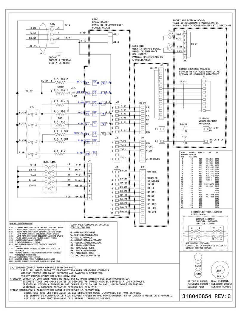
ESECSYSTEMDIAGRAM
SERVICE DATA SHEET
Electric Smoothtop Ranges with Electronic Surface Element Control (ESEC)
Notes on Replacing Parts
Replacing the Power Board* – When replacing the main control board (power board) on
the back of the range, do not over-tighten the 2 screws that secure the Power Board. A
torque of only 10 in.-lbs. is required to tighten the screws. Over-tightening the screws can
damage the plastic standoffs and possibly the board itself.
Replacing the TSEC – The Touch Sensor Electronic Control includes several parts and
must be replaced as an assembly.
Replacing the UIB* – When replacing the User Interface Board located in the backguard,
do not over-tighten the 4 screws that secure the UIB. To secure the UIB use NO MORE
THAN 20 in. - lbs. Over-tightening these screws can possibly damage the UIB board.
* NOTE: Electronic boards are very sensitive to static electricity. Static electricity can
permanently damage electronic boards. Before handling these parts, be sure to drain static
electricity from your body by properly grounding yourself.
ELECTRONICSURFACEELEMENTCONTROL(ESEC20)TROUBLESHOOTINGGUIDE
Surface
Elementhot,
but Hot
Surface
Indicator
Lights do not
glow
All displays
blank
Elementdoes
not come on
"PF"in
displays
"SD"in
displays
Power Board does not see 120 VAC (from element's hot surface
limiter) at P12 connector.
1. Five-wire connector from surface element harness not properly
connected to Power Board P12 connector.
2. Miswiring of surface element harness.
3. Bad surface element or Power Board.
1. ESEC wire harness not connected to UIB or Power Board.
2. Power Board not receiving power from harness.
3. Bad ESEC wire harness.
4. Bad Power Board or UIB.
5. Disconnected display ribbon or bad TSEC.
1. Miswiring at surface elements.
2. Miswiring at Power Board.
3. Bad Power Board.
Recent power failure or interruption of electrical service.
Appliance set for Display Mode.
1. Check the five-wire connector and seat properly to Power Board P12
connector.
2. Check surface harness for correct wiring from each element's hot surface
limiter - correct wiring or replace harness if necessary.
3. Turn on all elements to Hi. Wait a while to ensure all surfaces are hot.
Check the voltage from each input pin to Neutral at P12 - if one of them does
NOT read 120 VAC and the wiring from that element is correct, replace that
surface element or Power Board.
1. Check harness connections and reseat.
2. Verify that Neutral (white wire) is connected at teminal P1 and that L2 (red
wire) is connected at terminal P2 on the Power Board. Correct wiring or
replace harness if necessary.
3. Check continuity of ESEC harness connections. Replace harness if
necessary.
4. If connections and harness are okay, replace Power Board.
5. Re-power appliance & listen for audible beeps. If beeps are heard, check
ribbon cables and TSEC. If no beeps are heard, replace UIB.
1. Check wiring to surface elements. Correct wiring if necessary.
2. Check connections to Power Board terminals near relays & correct.
3. If wiring is correct, replace power board.
Touch any ESEC ON/OFF pad to reset display.
Re-power the appliance. Within 60 seconds touch and hold the Oven Cook
Time pad until "PF" appears in the displays. Touch any ESEC ON/OFF touch pad
to reset displays for normal use.
Symptom Likely Failure Condition/Cause Suggested Corrective Action
ESEC SYSTEM SCHEMATIC
"F5 00" in
displays Communication break between ES500 and UIB.
1. Bad ESEC wire harness
2. Damaged UIB/Power Board/ES500 connector.
3. UIB bad.
4. Power Board bad.
5. ES500 bad.
1. Check ESEC harness connections make sure that they are all connected
properly. If they are all good connections you have bad harness - Replace
harness.
2. Check if UIB/Power Board/ES500 connectors have been damaged in
assembly. If damaged - replace UIB/Power Board/ES500.
3. Replace UIB.
4. Replace Power Board.
5. Replace ES500.
"F7 10" in
displays UIB-TSEC Display Cable problem.
1. Display cable not properly seated in UIB connector.
2. Damaged UIB connector.
3. UIB bad.
4.TSECbad.
1. Re-seat display cable in UIB connector.
2. Check if UIB connectors have been damaged in assembly. If damaged - replace
UIB.
3. Replace UIB.
4.Replace TSEC.
"F7 01" in
displays UIB-TSEC Keypad Cable problem.
1. Keypad cable not properly seated in UIB connector.
2. Damaged UIB connector.
3. UIB bad.
4.TSECbad.
1. Re-seat keypad cable in UIB connector.
2. Check if UIB connectors have been damaged in assembly. If damaged - replace
UIB.
3. Replace UIB.
4.Replace TSEC.
"F7 02" in
displays UIB-Shorted keypad problem.
1. Keypad cable not properly seated in UIB connector.
2. Damaged UIB connector.
3. UIB bad.
4.TSECbad.
1. Re-seat keypad cable in UIB connector.
2. Check if UIB connectors have been damaged in assembly. If damaged - replace
UIB.
3. Replace UIB.
4.Replace TSEC.
Missing
segments in
displays
Missing the same segement in all displays - UIB bad.
Missing segment in only one display -TSEC bad. Missing same segment in all displays - Replace UIB.
Missing segment in only one display - Replace TSEC.
"F0 13" in
displays
FMEA (Failure Mode Effects Analysis).
1. Bad UIB.
1. Replace UIB.
"F0 15" in
displays
EEPROM Failure.
1.BadEEPROM.
1. Replace UIB.
NOTICE - This service data sheet is intended for use by persons having electrical and mechanical training and a level of
knowledge of these subjects generally considered acceptable in the appliance repair trade The manufacturer cannot be
responsible, nor assume any liability for injury or damage of any kind arising from the use of this data sheet
SAFE SERVICING PRACTICES
To avoid the possibility of personal injury and/or property damage, it is important that safe servicing practices be observed. The following
are examples, but without limitation, of such practices.
1. Before servicing or moving an appliance remove power cord from electrical outlet, trip circuit breaker to FF, or remove fuse.
2. Never interfere with the proper installation of any safety device.
3. GR UNDING: The standard color coding for safety ground wires is GREEN or GREEN WITH YELLOW STRIPES. Ground leads are
not to be used as current carrying conductors. It is extremely important that the service technician reestablish all safety
grounds prior to completion of service Failure to do so will create a potential safety hazard
4. Prior to returning the product to service, ensure that:
• All electric connections are correct and secure.
• All electrical leads are properly dressed and secured away from sharp edges, high-temperature components, and moving parts.
• All uninsulated electrical terminals, connectors, heaters, etc. are adequately spaced away from all metal parts and panels.
• All safety grounds (both internal and external) are correctly and securely reassembled.
Oven Calibration
Set the electronic oven control for normal baking at 350°F. btain an average oven temperature after a minimum of 5 cycles. Press STOP
or CLEAR keypad to end Bake mode.
Temperature Adjustment
1. While in a non-cooking mode, press and hold the BAKE key pad for 6 seconds.
2. The current calibration offset (temperature adjustment) should appear in the temperature display.
3. Use the number key pads (0-9) to enter the desired amount of adjustment (up to 35°F).
4. Press the CLEAN key pad to change the sign of the adjustment to a (-) if necessary. A positive adjustment will not display a sign.
5. nce the desired adjustment (-35° to 35° F) has been entered, press the START key pad to accept the change or the STOP or CLEAR
key pad to reject the change.
Note: Changing calibration affects all Baking modes. The adjustments made will not change the self-cleaning temperature.
RTD SCALE
Temperature (°F) Resistance (ohms)
32 ± 1.9 1000 ± 4.0
75 ± 2.5 1091 ± 5.3
250 ± 4.4 1453 ± 8.9
350 ± 5.4 1654 ± 10.8
450 ± 6.9 1852 ± 13.5
550 ± 8.2 2047 ± 15.8
650 ± 9.6 2237 ± 18.5
900 ± 13.6 2697 ± 24.4
SERVICE DATA SHEET
Electric Range with ES 575 Electronic Oven Control
p/n 316441478 REV A (0612) EN
Electronic Oven Control & Jumper Connections (EOC Rear View)
Resistance Temperature Detector (RTD) Resistance Temperature Detector Scale
Circuit
Analysis
Matrix
IMPORTANT
DO NOT REMOVETHIS BAG
OR DESTROYTHE CONTENTS
WIRING DIAGRAMS AND SERVICE
INFORMATION ENCLOSED
REPLACE CONTENTS IN BAG
Runaway Temperature
Shorted Keypad
Bad Micro Identification
Bad EEPROM Identification/Checksum error
Internal Control or Power Supply failure between
Power Supply Board & EOC
Communication failure between EOC & ESEC system
(for electric range models ONLY)
Communication failure with Mini Oven Control Board
(for models equipped with Bake-n-Warm™ ONLY)
Open Probe or connection
Shorted Probe or connection
Maximum oven door unlock time exceeded
Maximum oven door unlock attempts exceeded
Maximum oven door open time exceeded
Maximum oven door lock time exceeded
Maximum oven door lock attempts exceeded
Likely Failure Condition/Cause Suggested Corrective Action
Fault Code
1. (F10 only) Check RTD Sensor Probe & replace if necessary. If oven is overheating, disconnect
power. If oven continues to overheat when the power is reapplied, replace E C. Severe
overheating may require the entire oven to be replaced should damage be extensive.
2. (F11, 12 & 13) Disconnect power, wait 30 seconds and reapply power.
3. (F11, 12 & 13) If fault returns upon power-up, replace E C.
1. Check harness connectors at P2 on (Power Supply Board) & J2 connectors on (E C).
2. If harness and connections are good replace (Power Supply Board).
3. If Power Supply Board is good replace (E C).
1. Test harness/connections P4 (E C) & P7 (Surface Element Control Board)
2. If harness checks .K. failure can be caused by faulty UIB, Surface Element Control Board
or E C.
1. Check harness & connectors from the E C to Mini ven Control Board. Check for 15VDC
to Mini ven Control Board (red & gray wires). If harness and voltage are good replace Mini ven
Control Board. If fault returns replace the E C.
1. (F30 or F31) Check resistance at room temperature & compare to RTD Sensor resistance chart.
If resistance does not match the RTD chart replace RTD Sensor Probe. Check Sensor wiring
harness between E C & Sensor Probe connector.
2. (F30 or F31) Check resistance at room temperature, if less than 500 ohms, replace RTD Sensor
Probe. Check for shorted Sensor Probe harness between E C & Probe connector.
1. (F90, 91, 92, 93 & 94) Check the wiring between E C & Lock Motor Micro Switch.
2. (F90, 91, 92, 93 & 94) Replace the Motor Door Latch assembly if necessary.
3. (F90, 91, 92, 93 & 94) Check for binding of the Latch Cam, Lock Motor Rod & Lock Motor Cam.
4. (F90, 91, 92, 93 & 94) Check to see if Lock Motor Coil is open. If open, repl;ace Lock Motor
Assembly.
5. (F90, 91, 92, 93 & 94) Lock Motor continuosly runs - if Micro Switch is open, replace Lock Motor
Assembly.
6. (F92, 93 & 94) Check oven door Light Switch - if open, replace Switch.
7. If all situations above do not solve probem, replace E C.
F10
F11
F12
F13
F15
F20
F26
F30
F31
F90
F91
F92
F93
F94
Electonic Oven Control Fault Code Descriptions
General Troubleshooting Diagram General Troubleshooting Schematic

Other Frigidaire Range manuals

Frigidaire CFEH2411UW User manual

Frigidaire

Frigidaire CFEH2411UW User manual

Frigidaire GLEF396A User manual

Frigidaire

Frigidaire GLEF396A User manual

Frigidaire FEF362MXESC User guide

Frigidaire

Frigidaire FEF362MXESC User guide

Frigidaire GLGFS66A User manual

Frigidaire

Frigidaire GLGFS66A User manual

Frigidaire Professional FPGS3085K F User manual

Frigidaire

Frigidaire Professional FPGS3085K F User manual

Frigidaire FEF357CG User manual

Frigidaire

Frigidaire FEF357CG User manual

Frigidaire FFGF3052TWD User manual

Frigidaire

Frigidaire FFGF3052TWD User manual

Frigidaire 318200404 User manual

Frigidaire

Frigidaire 318200404 User manual

Frigidaire GLEF379DBA User manual

Frigidaire

Frigidaire GLEF379DBA User manual

Frigidaire 318203875 User manual

Frigidaire

Frigidaire 318203875 User manual

Frigidaire FPIF3093LFB Owner's manual

Frigidaire

Frigidaire FPIF3093LFB Owner's manual

Frigidaire FCFG3083AS Owner's manual

Frigidaire

Frigidaire FCFG3083AS Owner's manual

Frigidaire Gallery FGEC3045K B Instruction Manual

Frigidaire

Frigidaire Gallery FGEC3045K B Instruction Manual

Frigidaire FGGS3065PF User manual

Frigidaire

Frigidaire FGGS3065PF User manual

Frigidaire FFED3015PWA User manual

Frigidaire

Frigidaire FFED3015PWA User manual

Frigidaire FEF361A User manual

Frigidaire

Frigidaire FEF361A User manual

Frigidaire FGF375BH User manual

Frigidaire

Frigidaire FGF375BH User manual

Frigidaire Gallery FGEF3057KF User manual

Frigidaire

Frigidaire Gallery FGEF3057KF User manual

Frigidaire FGF337A User manual

Frigidaire

Frigidaire FGF337A User manual

Frigidaire FGF376CJS User manual

Frigidaire

Frigidaire FGF376CJS User manual

Frigidaire LFEF3016NWA Owner's manual

Frigidaire

Frigidaire LFEF3016NWA Owner's manual

Frigidaire PLGFZ390ECD User manual

Frigidaire

Frigidaire PLGFZ390ECD User manual

Frigidaire LGEF3043KF Owner's manual

Frigidaire

Frigidaire LGEF3043KF Owner's manual

Frigidaire GLGFM98GPBD User manual

Frigidaire

Frigidaire GLGFM98GPBD User manual

Popular Range manuals by other brands

Waldorf RN8910GC Installation and operation manual

Waldorf

Waldorf RN8910GC Installation and operation manual

Sharp KS-70S50BSS-EE user manual

Sharp

Sharp KS-70S50BSS-EE user manual

Thermador Pro Grand PRD364WLGU installation instructions
Thermador

Thermador Pro Grand PRD364WLGU installation instructions

Kenmore 790. 7136 Use & care guide

Kenmore

Kenmore 790. 7136 Use & care guide

GE JDP39 owner's manual

GE

GE JDP39 owner's manual

Smeg C30GGNU manual

Smeg

Smeg C30GGNU manual

Electrolux EKG4120AOW user manual

Electrolux

Electrolux EKG4120AOW user manual

Saturn SHP2-HD owner's manual

Saturn

Saturn SHP2-HD owner's manual

Midea MGS30S2AST installation instructions
Midea

Midea MGS30S2AST installation instructions

Jenn-Air JGR8895BDS12 Use & care guide

Jenn-Air

Jenn-Air JGR8895BDS12 Use & care guide

Maytag MGR6775ADW Use & care guide

Maytag

Maytag MGR6775ADW Use & care guide

Whirlpool WT-TOD user guide

Whirlpool

Whirlpool WT-TOD user guide

Whirlpool 9761040 Use and care guide

Whirlpool

Whirlpool 9761040 Use and care guide

Whirlpool WFC340S0AB0 User instructions
Whirlpool

Whirlpool WFC340S0AB0 User instructions

Amana AGR5844VDW0 parts list

Amana

Amana AGR5844VDW0 parts list

Thermador PRD364JDGC installation manual

Thermador

Thermador PRD364JDGC installation manual

Samsung NX60A6711SG user manual

Samsung

Samsung NX60A6711SG user manual

Kenmore 790.3263 Series Use & care guide

Kenmore

Kenmore 790.3263 Series Use & care guide

manuals.online logo
manuals.online logoBrands
  • About & Mission
  • Contact us
  • Privacy Policy
  • Terms and Conditions

Copyright 2025 Manuals.Online. All Rights Reserved.