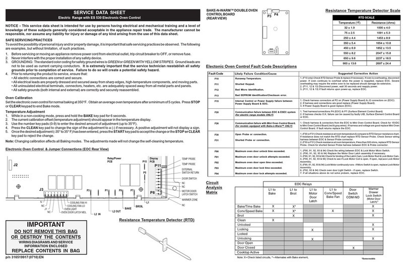
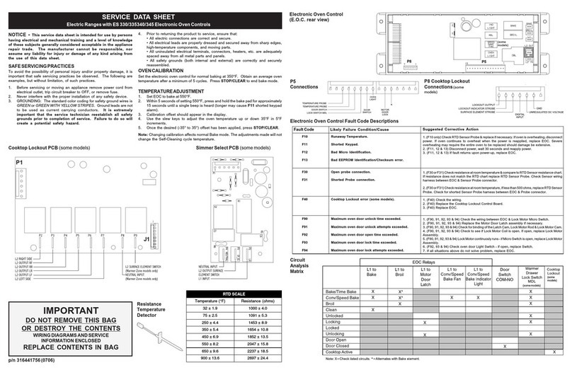
NOTICE - This service data sheet is intended for use by persons having electrical and mechanical training and a level of knowledge of these subjects
generally considered acceptable in the appliance repair trade. The manufacturer cannot be responsible, nor assume any liability for injury or damage
of any kind arising from the use of this data sheet.
SAFESERVICINGPRACTICES
To avoid the possibility of personal injury and/or property damage, it is important that safe servicing practices be observed. The following are examples, but without
limitation, of such practices.
1. Before servicing or moving an appliance remove power cord from electrical outlet, trip circuit breaker to OFF, or remove fuse.
2. Never interfere with the proper installation of any safety device.
3. GROUNDING: The standard color coding for safety ground wires is GREEN or GREEN WITH YELLOW STRIPES. Ground leads are not to be used as current
carrying conductors. It is extremely important that the service technician reestablish all safety grounds prior to completion of service. Failure to
do so will create a potential safety hazard.
4. Prior to returning the product to service, ensure that:
• All electric connections are correct and secure.
• All electrical leads are properly dressed and secured away from sharp edges, high-temperature components, and moving parts.
• All uninsulated electrical terminals, connectors, heaters, etc. are adequately spaced away from all metal parts and panels.
• All safety grounds (both internal and external) are correctly and securely reassembled.
CONVECTION / SPEED BAKE MODE (some models)
The Convection/Speed Bake mode uses the addition of a fan to move the heated air already in the oven. Moving the heated air helps to destratify the heat and
cause uniform heat distribution. Cooking times can be reduced by as much as 30%. The air is drawn in through a fan shroud located in the rear wall of the oven.
It is then discharged around the outer edges of this shroud. The air circulates around the food and then enters the shroud again. As with conventional electric
ranges, there is still an oven vent which discharges behind or through the top cooking surface.
To set the oven to Convection/Speed Bake mode, follow these steps:
1. Program the oven as you normally would for baking.
2. Push and release the Convection/Speed Bake momentary rocker switch. The indicator light will glow and the fan will come on. The fan stays on when the
oven door is closed and shuts off while the oven door is opened. The fan will continue to operate until baking is complete.
3. To cancel the Convection/Speed Bake function, push CANCEL or STOP/CLEAR on the oven control as you would to cancel any baking function.
NOTE: The Convection/Speed Bake mode will not work during a Self-Clean or Broil cycle.
FAN MOTOR (Convection/SpeedBake models only)
The fan motor is mounted on the main back on the back side of the range. It can be accessed by removing the rear wire shields.
FANBLADE (Convection/SpeedBakemodelsonly)
The fan blade is mounted in the rear of the unit and has a "D" shaped mounting hole. Only minimum clearance exists between the oven back, fan blade, and fan
shroud. Be careful not to bend the blade when removing or installing.
Access to the fan blade is gained by removing the fan shroud located inside the oven and held in place by two screws.
The fan blade is held in place with a 13 mm hex nut that has left handed threads. When removing this nut, gently hold the fan blade, and turn the nut clockwise.
If one of the blades becomes deformed, it may be bent back into shape using a flat surface as a reference. A flat washer is located on the motor shaft between
the snap ring on the shaft and the fan blade.
• Is the oven control in Bake mode?
• Is the Convection/Speed Bake indicator light glowing?
• Are 120 volts available at the fan motor?
• Is the fan motor coil resistance 14.5 ohms ±10%?
• Is the door/light switch working properly?
MOTORMOUNTINGBRACKET(Convection/SpeedBakemodelsonly)
The fan motor on the rear of the range is mounted through the main back to a mounting bracket
thatis attached with threescrewsto the backside ofthe rear oven wall. Shoulditbecome necessary
to replace this bracket, the main back must be removed to access the mounting screws.
OVEN CALIBRATION
Set the electronic oven control for normal baking at 350°F. Obtain an average oven temperature after a
minimum of 5 cycles. Press CANCEL or CLEAR to end bake mode.
TEMPERATUREADJUSTMENT
1. Set EOC to bake at 550°F.
2. Within 5 seconds of setting 550°F, press and hold the bake pad for approximately 15 seconds until a single beep is heard (longer may cause F1 shorted keypad
alarm).
3. Calibration offset should appear in the display.
4. Use the slew keys to adjust the oven temperature up or down 35°F in 5°F increments.
5. Once the desired (-35° to 35°) offset has been applied, press CANCEL or STOP/CLEAR.
Note: Changing calibration affects both Convection/Speed Bake and normal Bake modes. The adjustments made will not change the self-cleaning temperature.
P/N 316218513(0307)
SERVICE DATA SHEET
ElectricRanges with ElectronicOven Control& Convection/Speed Bake (somemodels)Cooking System
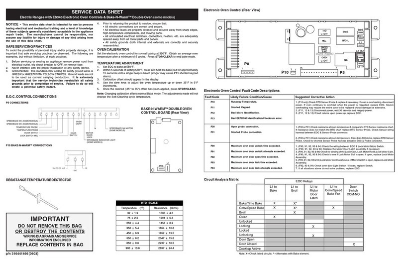
RTD SCALE
Temperature (°F) Resistance (ohms)
32 ± 1.9 1000 ± 4.0
75 ± 2.5 1091 ± 5.3
250 ± 4.4 1453 ± 8.9
350 ± 5.4 1654 ± 10.8
450 ± 6.9 1852 ± 13.5
550 ± 8.2 2047 ± 15.8
650 ± 9.6 2237 ± 18.5
900 ± 13.6 2697 ± 24.4
Electrical Shock Hazard can
occur and result in serious injury or death.
Disconnect appliance from electric power before
cleaning and servicing the warmer drawer.
To Remove Warmer Drawer:
Figure 1 Figure 2
REMOVINGANDREPLACINGWARMERDRAWER(somemodels)
ELECTRONICOVENCONTROLFAULTCODEDESCRIPTIONS
Note: Only three fault codes are displayed by this control - F1, F3 or F9. Generally, F1 display implies the electronic oven control itself has detected an internal
malfunction. F3 implies the control has detected a sensor probe failure and F9 implies the control has detected a latch motor assembly problem. In any of these
cases, an alarm will accompany a displayed F1, F3 or F9.
1. Shorted keypad.
2. Control's internal checksum may have become corrupted.
3. Controlhassensedapotentialrunawayovencondition.Controlmay
have shorted relay, RTD sensor probe may have gone bad.
1. OpenRTDsensor probe.Note:The EOCwillinitially displayanF1 for
this condition. The EOC thinks a runaway oven condition exists.
2. ShortedRTDsensorprobe.Note:TheF3forshortedprobeshouldonly
occur when the oven is active or when an attempt is made to enter a
mode.
Control has detected a problem with the Motor Door Latch Assembly.
Likely Failure Condition/Cause Suggested Corrective Action
Fault Code
1. ReplaceEOC.
2. Disconnect power, wait 30 seconds and reapply power. If fault returns upon
power-up,replaceEOC.
3. Check RTD sensor probe and replace if necessary. If oven is overheating,
disconnectpower.Ifovencontinuestooverheatwhenthepowerisreapplied,
replaceEOC.Severeoverheatingmayrequiretheentireoven tobereplaced,
should damage be extensive.
1. CheckresistanceatroomtemperatureandcomparetoRTDsensorresistance
chart. If resistance does not match the chart, replace RTD sensor probe.
2. Check resistance at room temperature, if less than 500 ohms, replace RTD
sensor probe.
Check the wiring. Replace the Motor Door Latch Assembly if necessary.
F3
F1
F9
ELECTRONICOVENCONTROL(REARVIEW)
Note: If the fan blade is bent and the motor vibrations increase, the noise made by the fan will be
greater.
FANOPERATION(Convection/SpeedBakemodelsonly)
The fan motor runs continuously while in Convection/Speed Bake mode unless the door is opened.
If the fan does not operate, check the following:
IMPORTANT
DO NOT REMOVE THIS BAG
OR DESTROY THE CONTENTS
WIRINGDIAGRAMSANDSERVICE
INFORMATION ENCLOSED
REPLACE CONTENTS IN BAG
1. Turn power off before removing the warmer drawer.
2. Open the drawer to the fully opened position.
3. On the right glide you will find a shield attached with a hex-head screw
(see figure 1). Using a 1/4”socket and ratchet remove the shield.
4. Locate glide lever on each side of drawer, pull up on the left glide lever
and push down on the right glide lever.
5. Pull the drawer away from the range.
To Replace Warmer Drawer:
1. Replace shield on the right glide of the drawer body.
2. Pull the bearing glides to the front of the chassis glide (see figure
2).
3. Aligntheglideoneachsideofthedrawerwiththeglideslotsontherange.
4. Push the drawer into the range until levers “click”(approximately 2”).
Pull the drawer open again to seat bearing glides into position. If you
do not hear the levers “click” or the bearing glides do not feel
seated remove the drawer and repeat steps 2-4. This will minimize
possible damage to the bearing glides.
RESISTANCE
TEMPERATURE
DETECTOR
