Fristam Pump FZP 10 Assembly instructions

Original Instructions
Assembly Instructions
Side Channel Pump
FZ Series
Pump Type:
Pump No.:

Copyright
© Copyright 2012 Fristam Pumpen KG (GmbH & Co.)
All rights reserved. The contents, including graphic images and layout of this operating instructions
manual are subject to copyright protection and to other laws for the protection of intellectual property.
The publication and modification of the contents are not authorised. Moreover, you may not copy,
publish and alter the contents therein for commercial purposes, or transmit the information to a third
party.
The German version is the original version of the operating instructions manual.
Other languages are translations of the original operating manual.

3
Table of contents
1 Introduction............................................................. 5
1.1 Foreword................................................................... 5
1.2 Manufacturer........................................................... 5
1.3 Scope of Supply...................................................... 5
1.4 Pump Without Motor (Optional)...................... 5
1.5 Scope of Documentation.................................... 5
1.6 Display Conventions............................................. 5
2 Safety Instructions................................................. 6
2.1 Basic Safety Instructions...................................... 6
2.2 Intended Use ........................................................... 6
2.3 Improper Use........................................................... 6
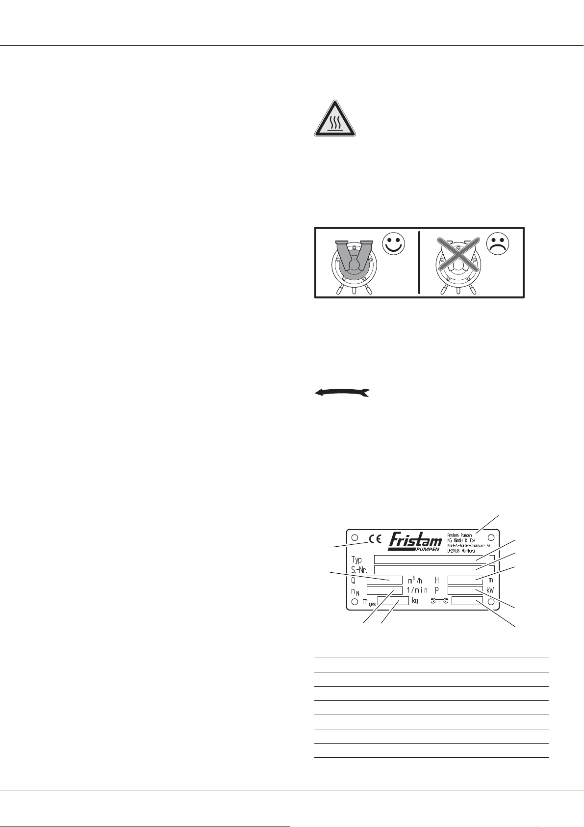
2.4 Warning and Instruction Labels........................ 6
2.5 Noise Emissions ...................................................... 7
2.6 Disposal ..................................................................... 7
3 Design and Function ............................................ 7
3.1 Principles of Design............................................... 7
3.2 Models ....................................................................... 8
3.3 Pump Key.................................................................. 9
3.4 Versions ..................................................................... 9
3.5 Pump Sizes ............................................................... 9
4 Transportation ........................................................ 10
4.1 Safety Instructions................................................. 10
4.2 Moving With Industrial Trucks .......................... 10
4.3 Moving With Crane ............................................... 10
5 Storage....................................................................... 11
5.1 Safety Instructions................................................. 11
5.2 Storage Conditions................................................ 11
5.3 Long-Term Storage ............................................... 11
5.4 Recommissioning .................................................. 11
6 Installation................................................................ 11
6.1 Safety Instructions................................................. 11
6.2 Installation Location ............................................. 11
6.3 Reduction of Noise and Vibration.................... 12
6.4 Pump Fixation ........................................................ 12
6.5 Electrical Connection........................................... 13
6.6 Connection of Sealing or Quenching
Liquid (Optional) ................................................... 13
6.7 Cleaning.................................................................... 13
7 Operation................................................................. 14
7.1 Safety Instructions ................................................ 14
7.2 Commencement of Operation......................... 14
7.3 Monitoring of Operation .................................... 14
7.4 Stopping of Operation ........................................ 14
7.5 Pump Decommissioning.................................... 14
7.6 Cleaning in Place ................................................... 15
8 Faults ......................................................................... 15
8.1 Safety Instructions ................................................ 15
9 Maintenance........................................................... 15
9.1 Safety Instructions ................................................ 15
9.2 Replacement Parts................................................ 15
9.3 Inspection of Sealing and Quenching
Liquid (Optional) ................................................... 16
9.4 Lubrication of Motor Bearings.......................... 16
9.5 Lubrication of Shaft Bearing ............................. 16
9.6 Motor Replacement ............................................. 17
9.7 Shaft Seal Replacement ...................................... 18
9.8 Pump Head Removal ........................................... 18
9.9 Checking of the Clearances............................... 20
9.10 Pump Head Attachment..................................... 20
9.11 Design FZ 27: Mounting and aligning the
pump shaft .............................................................. 29
9.12 Model L: Coupling Replacement ..................... 30
10 Appendix 1 .............................................................. 31
10.1 Specifications.......................................................... 31
10.2 Maintenance Intervals......................................... 31
10.3 Troubleshooting Table........................................ 32
10.4 Number Key ............................................................ 34
10.5 EC Declaration of Conformity........................... 35
10.6 EG Declaration of Incorporation...................... 35

/ / FZ pump series / / /
4
11 Appendix 2 – Assembly Instructions
(Optional).................................................................. 36
11.1 Safety Instructions................................................. 36
11.2 Scope.......................................................................... 36
11.3 Moving Without Motor........................................ 36
11.4 Installation Location ............................................. 37
11.5 Pump Installation................................................... 37

5
1Introduction
1.1 Foreword
This operator's manual describes all sizes, models, and versions
of the FZ pump series.
Information on the model, size, and version of your pump can
be found on the rating plate on your pump and in the "Order-Re-
lated Documents" in Appendix 2.
1.2 Manufacturer
FRISTAM Pumpen KG (GmbH & Co.)
Kurt-A.-Körber-Chaussee 55
21033 Hamburg
GERMANY
Tel.: +49-40-72556-0
Fax: +49-40-72556-166
E-mail: [email protected]
1.3 Scope of Supply
The package includes the following items:
– Pump with motor = pump unit
optional: without motor
– Covers for pipe fittings
– Optional: assembly kit
–Fristam accessories (if applicable)
– Documentation
►Check the shipment for completeness and damage. Immedi-
ately notify Fristam of any missing items or damage.
1.4 Pump Without Motor (Optional)
The pump can optionally be supplied without a motor. In this
case, continue reading up to and including Chapter 3, "Design
and Function," page 7, and then skip to Chapter 11, "Appendix 2 –
Assembly Instructions (Optional)," page 36.
1.5 Scope of Documentation
The documentation includes the following items:
–This operator's manual
– Maintenance, lubrication, and tightening torque tables
can be found in Appendix 1.
– The assembly instructions for the option "Pump Without
Motor" can be found in Appendix 2.
–Attached documents
– Order-Related Documents
– Supplier Documentation (motor, coupling, etc.)
– Documentation on Fristam accessories (if applicable)
– Certificates (materials certificates, etc.), if applicable
– Declaration of Conformity
1.6 Display Conventions
List items are preceded by dashes:
–Part1
–Part2
Handling instructions that must be performed in a specified or-
der are numbered:
1. Turn device on.
2. Turn device off.
Handling instructions that do not need to be performed in a
specified order are preceded by triangular bullets:
►Action
►Action
1.6.1 Safety Instructions
A safety instruction with the signal word "Danger" indicates per-
sonal hazards causing death or serious injury.
A safety instruction with the signal word "Warning" indicates
personal hazards that may lead to death or serious injury.
A safety instruction with the signal word "Caution" indicates per-
sonal hazards that may lead to mild to moderate injuries.
A safety instruction with the signal word "Note" warns of the
possibility of material damage.

/ / FZ PUMP SERIES / / /
6
2 Safety Instructions
2.1 Basic Safety Instructions
►Please read this operator's manual completely before using
the pump and keep it available at the pump installation loca-
tion.
►Heed the applicable national regulations of the owner's
country and the company's work and safety regulations.
►All work described here may only be performed by qualified
experts with caution.
►Danger of contamination: Heed legal and operational safety
regulations when pumping dangerous media.
2.2 Intended Use
The standard versions of the FZ pump series are designed for
use in the food industry, the pharmaceutical and biotechnology
industry, and CIP process technology.
FZ pump series pumps are used for the following applications:
– Pumping of products containing gas
– Venting of suction lines
– Emptying of residues in product lines
The FZ pump series can generate discharge pressures of up to
7.0 bar. Depending on the pump size, the system pressure can
reach 15 bar.
Each pump is designed according to customer requirements.
The seal materials have been selected for the respective pump-
ing conditions (medium, pressure, temperature). The pump may
only be used to pump the medium it was designed for
(see Order-Related Documents in the attached documents in
Appendix 2).
2.3 Improper Use
The standard FZ pump series versions may not be used in explo-
sive atmospheres. Special explosion-proof versions are available
for this.
Pumping of media other than those specified can destroy the
pump.
Standard pump units from Fristam are described in this opera-
tor's manual. If nonstandard items or extras are installed, the op-
erator assumes the responsibility for operation.
Modifications and changes to the pump are only permissible
with the explicit consent of Fristam.
2.4 Warning and Instruction Labels
►Do not alter or remove the labels on the pump.
►Immediately replace damaged or lost labels with ones that
are true to the originals.
2.4.1 Hot Surface
Fig. 1 Safety label: "Hot Surface"
This label indicates that parts can become hot during operation
or, if applicable, that hot media is being pumped. Only touch
the pump if you are wearing suitable gloves.
2.4.2 No Dry Running
Fig. 2 Safety label: "No Dry Running"
This label indicates that the pump cannot be run dry. There
must always be medium in the suction line and the pump when
the pump is started. Otherwise, the pump will be damaged.
2.4.3 Direction of Rotation
Fig. 3 "Impeller Direction of Rotation" label
This label shows the direction of rotation of the impeller. It is lo-
cated at the front on the pump cover.
Fristam can provide operation independent of the direction of
rotation for special versions.
2.4.4 Rating Plate
Fig. 4 Pump unit rating plate
1Manufacturer
2Typ: pump series, pump size, model, version
3S.-Nr.: serial number of the pump
4H: discharge head [m]
5P: motor output [kW]
6Year of manufacture
7mttl: mass (total) [kg]
1
2
3
5
4
6
7
8
9
10

7
2.5 Noise Emissions
►The local noise exposure regulations must be complied with.
For noise emission values for the pumps, please see
Chapter 10.1, "Specifications," page 31.
Noise Generated by Running Pump
Hearing damage.
►Wear ear protectors when using pumps with specified sound
pressure levels of greater than 80 dBA.
2.6 Disposal
2.6.1 Disposal of Transportation Package
►Recycle the transportation package.
2.6.2 Models K, KF, and L 1: Disposal of Grease
►Dispose of grease and objects saturated with grease in an
environmentally friendly manner in accordance with applica-
ble regulations.
2.6.3 Model L 2: Disposal of Lubricating Oil
►Dispose of oil and objects saturated with oil in an environ-
mentally friendly manner in accordance with applicable reg-
ulations.
2.6.4 Disposal of Pump
1. Carefully clean the pump. Dispose of residues in an environ-
mentally friendly manner in accordance with applicable reg-
ulations.
2. Dismantle the pump into its constituent parts.
3. Dispose of the pump parts in an environmentally friendly
manner in accordance with applicable regulations.
2.6.5 Disposal of Electrical and Electronic Scrap
►Dispose of electrical and electronic scrap in accordance with
applicable directives.
3 Design and Function
3.1 Principles of Design
Fig. 5 Principles of design of pumps illustrated using the K model
3.1.1 Pump Head (A)
Fig. 6 Pump head
Shaft Seal (12)
Two seal types are available for use:
– Single shaft seal
– Double shaft seal
With the double shaft seal, there are two additional connections
for the sealing liquid on the pump casing. These connections are
not shown in the figures in this operator's manual.
8nR:rated speed [1/min]
9Q: flow rate [m³/h]
10 CE mark
APump head
BLantern
CElectric motor
11 Suction/discharge line connection
12 Shaft seal
13 Impeller
14 Pump cover
15 Pump casing
B
C
A
11
12
13
14
15

/ / FZ PUMP SERIES / / /
8
Impeller (13)
Open impellers with radial blades are standardly used in the
FZ pump series.
Pump Cover (14)
The connections for the suction and discharge lines are located
on the pump cover.
Pump Casing (15)
The impeller and the shaft seal are built into the pump casing.
3.1.2 Lantern (B) and Electric Motor (C)
Fig. 7 Lantern and electric motor
Lantern (16)
The lantern is present in all models except the special motor.
The lantern connects the pump casing to the motor. Two differ-
ent versions are possible, depending on pump size:
– The pump casing is screwed to the lantern via a flange con-
nection.
– The pump casing is inserted into the lantern and mounted
with a clamp.
Models with lanterns:
–FZP
–K
Compact bearing support. An additional bearing for the
pump shaft is located inside the lantern.
–KF
Compact bearing support with base. An additional bearing
for the pump shaft is located inside the lantern with base.
–L
Bearing block. An additional bearing for the pump shaft is
located inside the lantern with base. The pump shaft is con-
nected to the motor via a coupling.
Electric Motor (19)
The following motor types can be mounted:
– IEC standard motor with drive side fixed bearing (A side),
feather key and shaft pin of the following types:
– IM B3: motor model with base
– IM B5: motor model with flange
– IM B3/B5: motor model with flange and base
Various mounting types are possible for the IEC standard
motor:
–AFristam pump shaft is clamped to the motor shaft pin.
– The motor is fastened to the flange on the compact bear-
ing support (with base).
– The motor is connected to the bearing block via a cou-
pling.
–SpecialmotorwithFristam pump shaft
With the special motor, the Fristam pump shaft is already in-
tegrated and connected permanently to the motor.
3.2 Models
The model is indicated on the rating plate. See Chapter 2.4,
"Warning and Instruction Labels," page 6.
The following are shown as examples:
– Lantern clamp-mounted
– Without enclosure
See Chapter 3.4, "Versions," page 9.
3.2.1 Model FZ or FZP
Fig. 8 Model FZ with special motor
16 Pump shaft
17 Lantern
18 Electrical connection
19 Electric motor
16 17 18 19
Motor: Special motor
Design: Without lantern

9
3.2.2 Model K
Fig. 9 Model KF
3.2.3 Model KF
Fig. 10 Model KF
3.2.4 Model L
Fig. 11 Model L
3.2.5 Design FZ 27
Fig. 12 Design FZ 27
3.3 Pump Key
Fig. 13 Type designation example
3.4 Versions
3.5 Pump Sizes
Motor: IEC standard motor, motor model B3/B5
Design: Compact bearing support
Motor: IEC standard motor, motor model B5
Design: Compact bearing support with base
Motor: IEC standard motor, motor model B3
Design: Bearing block with coupling, coupling protec-
tion, base frame
Motor: IEC standard motor, model B3/B5
Design: With lantern
20 Pump type
21 Supplementary character 1
22 Pump size
23 Supplementary character 2
(20) Pump Type
FZ Side channel pump
(21) Supplementary Character 1
P Sampling pump (FZ 10)
(22) Pump Size
__ Sizes: see Chapter 3.5, "Pump Sizes," page 9.
(23) Supplementary Character 2
PM Powder mixer
A, B, C, D Versions; see Chapter 3.4, "Versions," page 9:
K Compact bearing support
KF Compact bearing support with base
L1, L2
Bearing block with coupling
H Pump casing with heating jacket
h Pump cover with heating jacket
Version Enclosure Spherical Cap
Legs
Motor Foot
AWith With Without
BWithout Without With
CWithout With Without
DWith Without With
Table 1 Versions
Pump Sizes
10
15
17
20
Table 2 Pump sizes
20 22 2321

/ / FZ PUMP SERIES / / /
10
Note: If the (optional) pump without motor is supplied, please
first read Chapter 11, "Appendix 2 – Assembly Instructions (Option-
al)," page 36.
4Transportation
Transportation may only be performed by trained personnel.
The pump can be moved using an industrial truck or a crane.
Always move the pump in the installation condition.
4.1 Safety Instructions
►Danger of injury from falling or unsecured parts.
– Only use suitable means of conveyance and hoists. Infor-
mation on pump weight can be found on the pump's rat-
ing plate as well as in the Order-Related Documents in Ap-
pendix 2.
– Before moving the pump secure it to prevent it from tip-
ping over. Secure the pump to the pallet with tie-down
straps, or screw the pump to the pallet.
– Do not leave the pump in a raised position for longer
than necessary.
►Damage to pump by contamination, impact, or moisture.
– Remove the pipe fitting covers just prior to connection to
the pipes.
4.2 Moving With Industrial Trucks
Preparation
►Ensure that the pump is adequately secured to the pallet.
Procedure
1. Pick up the pallet with the forks on the industrial truck.
2. Carefully move the pallet to the designated location and set
down.
Fig. 14 Moving with industrial truck
4.3 Moving With Crane
Falling Parts
Death from crushing, pinching of extremities, material damage.
►Do not lift the pump at the eyebolts on the motor and pump
casing to move because these eyebolts are not designed for
the total weight.
►Only use hoists that are designed for the total weight of the
pump.
►Ensure that the area below the pump is clear of people.
Swinging Parts
Crushing and serious injuries.
►Start and stop the crane with pump smoothly.
►Ensure that the danger zone of the pump is clear of people.
Auxiliary Equipment
Hoists: round slings tested in accordance with DIN EN 1492-1
and 1492-2
Preparation
►Remove load-securing devices.
Procedure
1. Wrap the round sling twice around the back end of the mo-
tor. Do not lay over the fan shroud (see Fig. 15, "Moving with
crane," page 11).
2. Lay the other end of the round sling between the lantern
and the pump casing. Do not lay the round sling over any
sharp edges or corners.
3. Guide both loops to the crane hook and rotate by 180° to en-
sure that the belt will not slip on the hook.
4. For double shaft seal:
Note: Round sling compresses sealing water tubes. Material
damage to double shaft seal.
►Do not lay the round sling on the sealing water tubes.
5. Position the center of gravity to ensure that the pump is lift-
ed horizontally.
6. Lift the pump.
22
25
27
Pump Sizes
Table 2 Pump sizes

11
.
Fig. 15 Moving with crane
5Storage
5.1 Safety Instructions
►Corrosion: Condensation can build up under a tarp and de-
stroy the pump. Ensure adequate ventilation.
5.2 Storage Conditions
►Store the pump as follows:
– Dry, in low humidity
– Protected against frost and heat, optimally at a tempera-
ture of +20°C to +25°C
– Ventilated
– Dust-free
5.3 Long-Term Storage
For a storage time of longer than six months, heed the follow-
ing:
►The shaft seals must be specially treated before long-term
storage:
–For single shaft seal
The impeller nut must be loosened so that the seal can
relax and the sliding surfaces do not stick together.
–For double shaft seal
Remove the complete shaft seal and store separately to
prevent the sliding surfaces from sticking together.
Information on the shaft seal can be found in the Order-Re-
lated Documents in Appendix 2.
►All movable pump parts must be rotated every three
months.
5.3.1 Storage of Elastomers
Storage Conditions
– Storage temperature between +5°C and +20°C
– Relative air humidity below 70%
– No direct sunlight
– Deformation-free storage
5.4 Recommissioning
►After long-term storage and before commissioning, check
seals, bearings, and lubrication.
6Installation
6.1 Safety Instructions
►Danger of injury from falling parts.
– Wear safety shoes.
– Check load capacity and attachment of hoists.
►Danger of injury from unstable assembly.
– Tighten screws to the specified tightening torque (see
Chapter 10.1.1, "Tightening Torques for Screws and Nuts,"
page 31).
– Use a torque wrench or an impact driver with adjustable
torque.
►Material damage from swinging during adjustment of spher-
ical cap feet.
– Use spherical cap base plates.
6.2 Installation Location
For standard pumps, the installation location must meet the fol-
lowing requirements:
– Nonexplosive atmosphere
– Dust-free environment
– Ambient temperature: –20°C to +40°C
– Moisture and salt contents in ambient air:
The values are given in the motor supplier documentation. It
can be found in the attached documents (Appendix 2).
– Foundation sized adequately for the pump weight
– Horizontal and level installation surface, adequate installa-
tion surface strength for pump mass
– Adequate clearance for maintenance work
– Adequate air supply for motor cooling

/ / FZ PUMP SERIES / / /
12
6.3 Reduction of Noise and Vibration
6.3.1 Primary Measures
►Operate the pump in the optimum working range.
Note: Pump must not be blocked during operation. Pump
may only be throttled to the minimum allowable flow rate;
see "Performance Chart."
►Decouple the suction and discharge lines from vibrations.
– Support lines.
– Align lines.
– Install vibration isolators.
6.3.2 Secondary Measures
►Take structural measures such as the following:
– Acoustic paneling
– Enclosure in housing
6.4 Pump Fixation
Models FZ/K/FZP
►Versions A and C:
Set up the pump on the spherical cap bearings and align.
►Versions B and D:
Screw the pump on the motor foot to the foundation.
Model KF
►Versions A and C:
Set up the pump on the spherical cap bearings and align.
►Versions B and D:
Screw the pump on the compact bearing support with base
to the foundation.
Model L
►Versions A and C:
Set up the pump on base frame on the spherical cap bear-
ings and align.
►Versions B and D:
Screw the pump on the base frame to the foundation.
Design FZ 27
►Versions A and C:
Install and align the pump on the spherical cap bearings.
►Versions B and D:
Screw the pump on the pump base to the foundation.
Carriage (Optional)
1. Set up the pump at the installation location. Lock the locks
on the rollers (if present) or secure the carriage with chocks.
2. Ground the carriage to dissipate electrostatic charge.
3. Position hose line to ensure that it cannot be damaged.
6.4.1 Installation of Pipes
►Lay and connect pipes as follows:
– Keep the pipe resistance as low as possible: Avoid unnec-
essary installation of valves, elbows, and abrupt pipe
transitions.
Fig. 16 Pipe transitions
– Design pipe cross section so that no unnecessary pres-
sure losses or cavitation occurs in the suction area. Verify
this in the project planning stage.
– Install the suction lines in horizontal position or at a con-
stant dropping angle towards the pump unit. Rule out
the possibility of air pockets and dips in the pipes.
Fig. 17 Air pocket in pipe
Fig. 18 Dip in pipe
– Pipe bends upstream of suction connection: Heed mini-
mum clearance and minimum bend radius:

13
Fig. 19 Laying of the suction line
– Connect the pipes to the pump so that they are free of
tension and compression to ensure that no stresses are
applied to the pump.
– Secure pipes to ceilings, walls, or floor using pipe clamps.
– Align pipes flush with pump connections using a bracket.
6.5 Electrical Connection
Electrostatic Charge Buildup
Electric shock.
►Ground pipes and pump to dissipate electric charge.
Electrical connection may only be performed by a qualified elec-
trician.
1. Heed the connection values on the motor's rating plate. The
specified voltage must not be exceeded.
2. Connect the motor according to the circuit diagram in the
terminal box of the motor.
3. Protect cable feedthroughs against penetration by moisture.
Fig. 20 Direction of rotation of motor fan wheel
4. Turn on the motor for 2 to 3 seconds. Compare the direction
of rotation of the motor fan wheel against the direction indi-
cated by the arrow (if available) on the pump head.
5. Reverse the polarity if the pumping direction is incorrect.
6.6 Connection of Sealing or Quenching Liquid
(Optional)
In versions with double shaft seal, the seal chamber must be
flushed with a sealing or quenching liquid.
►Use a suitable medium as a sealing or quenching liquid.
To be suitable, the medium must fulfill the following condi-
tions:
– It must be clean and have good lubricating properties.
– It must be compatible with the product to be pumped.
– It must not be easily vaporized during operation.
6.6.1 Installing the pipelines
1. Install and seal the supplied flushing tubes.
2. As a standard, the feed line should be fitted at the bottom
of the shaft seal.
3. As a standard, the return line should be fitted at the top of
the shaft seal.
Fig. 21 Installing the pipelines
4. Install the following valves into the pipelines:
– Install the sight glass in the return line.
6.7 Cleaning
Only use cleaning agents that comply with the hygiene guide-
lines for the respective pumping medium.
1. Before sealing the pump ensure that there are no foreign ob-
jects inside the pump or pipes.
2. Seal the pump.
3. Connect the pipes.
5 - 10 x D
R ≥2 x D
D
24 Return line
25 Inlet
24
25

/ / FZ PUMP SERIES / / /
14
4. Thoroughly clean the pump and the pipe system before ini-
tial use.
7Operation
7.1 Safety Instructions
►Danger of burning: Pumping of hot media can cause the
pump to become very hot. Check the temperature before
touching the pump.
►Noise emissions: The A-weighted sound pressure level of the
pumps can be greater than 80 dBA. Always wear ear protec-
tors in the vicinity of the running pump.
►Danger of bursting: If the allowable pressure and tempera-
ture ranges are exceeded, the pump may burst or become
leaky. The pressure and temperature ranges for the pump
must be complied with (see Order-Related Documents in Ap-
pendix 2).
►Danger of bursting: Cold extinguishing agents used to extin-
guish a pump fire can cause the hot pump to burst. Do not
cool the pump down excessively when extinguishing the
fire.
►Pump running in reverse direction despite emergency shut-
off: If the pump is shut off using the emergency shut-off
function, it will run in reverse direction due to the pumping
medium in the discharge line. Install a check valve in the dis-
charge line.
►Destruction of shaft seal when pump runs in reverse direc-
tion. Reverse running destroys the springs in the shaft seal.
Always operate the pump in the direction of rotation. See
Chapter 2.4.3, "Direction of Rotation," page 6.
7.2 Commencement of Operation
Damage to Shaft Seals
If the pump runs without a pumping medium, the mechanical
seal will be damaged.
►Ensure that the pumping medium always reaches the upper
edge of the outlet side when turning pump on.
Damage to Double Shaft Seals
If the pump runs without a sealing medium, the shaft seal will
be damaged.
Ensure that during operation:
►The sealing liquid flows with the necessary pressure through
the double shaft seal.
The prescribed sealing fluid pressure is specified in the "Or-
der-related documents" in the sectional drawing of the shaft
seal. The "Order-related documents" are included in this op-
erating manual.
– Negative pressure in the seal chamber is not allowed.
If no pressure is noted in the "Sectional drawing of the shaft
seal", the following applies:
– A max. pressure of 0.2 bar is allowed for seals to which
sealing fluid is applied without pressure or which are
flushed.
►The temperature of the sealing liquid is maintained at
T < 70 °C.
1. Open the valve in the suction line.
2. Open the valve in the discharge line.
3. Completely fill the pump and suction line with pumping me-
dium. Allow any air pockets that are present to escape.
4. Turn on the motor. The pump now pumps against the
opened valve in the discharge line. This will limit the starting
current.
5. Slowly close the valve in the discharge line and adjust to the
working point.
7.3 Monitoring of Operation
During operation heed the following points:
– Damage to shaft seal: Regulation of the pump output via the
suction-side valve can lead to damage of the pump and the
shaft seals. Regulate the pump output only by means of the
discharge-side valve.
– Damage to pumping medium: If during operation the valve
in the discharge line is closed abruptly or for a long period of
time, water hammers can occur in the pump and lead to
damage to the pump and/or the pumping medium.
– Damage to pump: Exceeding of the output can lead to dam-
age of the pump and the shaft seals. Do not exceed the max-
imum speed of 1,750 rpm.
– Damage to motor during operation with frequency convert-
er: If the speed is too low, the motor will overheat. Please re-
fer to the motor supplier documentation in the attached
documents.
7.4 Stopping of Operation
1. Turn off the motor.
2. Close the valve in the suction line to prevent dry running of
the pump.
3. Open the valve in the discharge line.
7.5 Pump Decommissioning
1. Turn off the motor.
2. Close the valve in the suction line.
3. Close the valve in the discharge line.

15
4. De-energize the pump.
5. Empty the pump.
6. Clean the pump; see Chapter 6.7, "Cleaning," page 13.
7. Dry the pump.
8. Protect the interior of the pump from moisture, e.g., with sili-
ca gel.
9. Seal the pipe connections with caps to prevent penetration
of dirt and foreign objects.
10. Please see Chapter 5, "Storage," page 11 for additional steps.
7.6 Cleaning in Place
7.6.1 CIP Process
The FZ series pumps are suitable for the CIP (Cleaning In Place)
process. The following guidelines apply to the CIP process:
Example of a Cleaning Cycle
1. Perform preliminary flush with water.
2. Perform caustic flush with lye (NaOH; see Table 3 , "CIP clean-
ing").
3. Perform intermediate flush with water.
4. Perform acid flush with nitric acid (HNO3; see Table 3 , "CIP
cleaning").
5. Flush with water.
During cleaning a sufficiently high flow rate must be achieved.
The prerequisites for this are as follows:
– Pump differential pressure of 2–3 bar
– Sufficiently high discharge rate obtained through appropri-
ate pump size and pipe cross sections
If values deviate from these specifications, please contact Fris-
tam.
7.6.2 SIP Process
The FZ pump series can only be used with the SIP (Sterilization
In Place) process with the prior approval of Fristam.
Suitability depends on the selected elastomers.
The maximum process temperature is 145°C.
In ATEX operation, temperatures might deviate, see supplemen-
tary ATEX manual, "Temperature limits".
8Faults
For information on faults, possible causes, and remedies, please
see Chapter 10.3, "Troubleshooting Table," page 32.
8.1 Safety Instructions
►Danger of burning: Pumping of hot media can cause the
pump to become very hot. Check the temperature before
touching the pump.
►Pump running in reverse direction despite emergency shut-
off: If the pump is shut off using the emergency shut-off
function, it can continue to run in reverse direction due to
the pumping medium in the discharge line. Install a check
valve.
9 Maintenance
For information on maintenance intervals, please see
Chapter 10.2, "Maintenance Intervals," page 31.
9.1 Safety Instructions
►Rotating parts: Danger of injury. Before removing the cou-
pling guard and guard plate, turn off the pump motor and
prevent it from being able to be turned on accidentally.
►Danger of burning: Pumping of hot media can cause the
pump to become very hot. Check the temperature before
touching the pump.
►Electric shock: Liquids flowing through the system result in
buildup of electrostatic charge. Ground the pipes and the
pump.
►Uncontrolled outflow of liquids: Before maintenance or ad-
justment of the pump:
– Close the suction and discharge valves in front of and be-
hind the pump.
– Block off the sealing or quenching liquid line.
►Leaking liquids: Acid burns and contamination. Before open-
ing the pump completely empty the pump casing.
►Tension cracks: Do not rapidly cool the pump.
►Material damage from scratching of polished surfaces. For a
polished surface, use a copper socket wrench socket.
9.2 Replacement Parts
►Use of replacement parts that are not approved by Fristam
can lead to serious personal injury and material damage. If
you have any questions regarding approved replacement
parts, please contact Fristam.
Medium Process Temperature [°C]
NaOH (approx. 1%–2%) 80–85
HNO3 (approx. 1%) 60–65
Table 3 CIP cleaning

/ / FZ PUMP SERIES / / /
16
►Fristam registers all shipped pumps. For ordering replace-
ment parts from Fristam, you require the following informa-
tion:
Serial number: see
– rating plate or
– number stamped into pump casing.
9.3 Inspection of Sealing and Quenching Liq-
uid (Optional)
For pumps equipped for "locking system" or "quenching sys-
tem," the sealing liquid head must be checked daily.
►Check the sealing liquid head and compare with the speci-
fied value.
The specified value can be found in the Order-Related Docu-
ments on the "Sectional Drawing" of the shaft seal. The Order-
Related Documents are attached to this operator's manual in
Appendix 2.
►The sealing liquid is heated by hot pumping medium and by
operation of the pump.
Ensure that the temperature of the sealing medium is suffi-
ciently lower than the evaporation point during operation.
9.4 Lubrication of Motor Bearings
►Lubricate the motor bearings in accordance with the motor
manufacturer's specifications (see "Motor Supplier Documen-
tation").
9.5 Lubrication of Shaft Bearing
The pump models FZ and FZP with special motor do not have
additional shaft bearings, and therefore must not be lubricated.
9.5.1 Model L 2
For model L 2, the oil must be changed at regular intervals.
1. Turn on the motor and let it run until the normal operating
temperature is reached.
2. Turn off the motor and prevent it from being able to be
turned on accidentally.
3. Place a suitable oil collection container under the oil drain
plug.
4. Caution! Danger of burning from hot oil.
►Wear suitable protective gloves.
►Loosen and remove the oil drain plug.
5. Drain the oil completely and dispose of oil in accordance
with local regulations.
6. Clean and remount the oil drain plug and seal.
7. Fill with new oil. We recommended using the: SAE 15W40 oil
type. Alternatively, use an equivalent brand of lubricant of
similar quality and viscosity.
Oil volume = 1 liter
9.5.2 Model L1
►Do not relubricate the deep groove ball bearing, but replace
it completely.
– At constant operating conditions, the raising of power con-
sumption, noise level or vibration indicates that wear has oc-
curred. Replace the deep groove ball bearing consequently.
Prerequisites
– Pump head has been removed.
– Motor with coupling has been removed.
Procedure
Fig. 22 Bearing block cover
1. Take the cover (26) off of the bearing block (27).
Fig. 23 Model L1, pump shaft, pump-side
2. Remove the bearing cap (28) on the pump side.
26
27
28

17
Fig. 24 Model L1, pump shaft, motor-side
3. Remove the bearing cap (29) on the motor side.
4. Force out the shaft in the direction of the pump head.
Note: All parts that are gray in the above two figures remain
on the shaft.
5. Clean the surfaces of all parts and check for damage. Replace
if necessary.
6. Relubricate the angular contact ball bearing. We recom-
mended using: JAX Halo-Guard FG-2 bearing grease or alter-
natively a white NSF H1 grease. Alternatively, use an equiva-
lent brand of lubricant of similar quality and viscosity.
Bearing grease amount = 10 g
7. Press the pump shaft with the bearing into the bearing
block.
8. Mount the bearing cap on the motor side.
9. Mount the bearing cap on the pump side.
10. Mount the cover (26).
9.5.3 Models K and KF
►Do not relubricate the deep groove ball bearing, but replace
it completely.
–At constant operating conditions, the raising of power
consumption, noise level or vibration indicates that wear
has occurred. Replace the deep groove ball bearing con-
sequently.
►Grease the cylindrical roller bearing with bearing grease.
Prerequisites
– Pump head has been removed.
– Motor has been removed.
Procedure
1. Remove the bearing cap (32).
2. Force out the pump shaft (30) with the bearing toward the
motor side.
Fig. 25 Model KF, shaft bearing
3. Remove the bearing nut (33) and the guard plate (34).
4. Remove the outer race of the cylindrical roller bearing.
Note: All parts that are gray in the above figure remain on
the shaft.
5. Clean the surfaces of all parts and check for damage. Replace
if necessary.
6. Relubricate the cylindrical roller bearing (31). We recom-
mended using: JAX Halo-Guard FG-2 bearing grease or alter-
natively a white NSF H1 grease. Alternatively, use an equiva-
lent brand of lubricant of similar quality and viscosity. See
Table 4 , "Bearing grease amounts: model KF".
7. Put the outer race back onto the shaft.
8. Place the guard plate and the bearing nut on the shaft, and
tighten the bearing nut.
9. Press the pump shaft with the bearing back into the lantern.
10. Mount the bearing cap (32).
11. Remount the cover (26) on the bearing block (27); see
Fig. 22, "Bearing block cover," page 16.
9.5.4 Design FZ 27
The model FZ27 has no additional shaft bearing and therefore
needs no lubrication.
9.6 Motor Replacement
Special Motor
1. Turn off the motor and prevent it from being able to be
turned on accidentally.
2. Remove the pump head (see Chapter 9.8, "Pump Head Remov-
al," page 18).
3. Replace the special motor.
4. Replace the mechanical seal if necessary, and mount the
pump head (see Chapter 9.10, "Pump Head Attachment,"
page 20).
Model Bearing Grease Amount
K1 and KF 1 20 g
K2 and KF 2 40 g
K3 and KF 3 60 g
Table 4 Bearing grease amounts: model KF
29
34 32
31
33
30

/ / FZ PUMP SERIES / / /
18
IEC Standard Motor for Models K and KF
1. Turn off the motor and prevent it from being able to be
turned on accidentally.
2. Take the motor off of the compact bearing support or the
compact bearing support with base.
3. Dispose of the motor in an environmentally friendly manner.
See Chapter 2.6.5, "Disposal of Electrical and Electronic Scrap,"
page 7.
4. Insert the key of the old motor into the new motor.
5. Screw the motor to the compact bearing support or the
compact bearing support with base.
IEC Standard Motor for Model L
1. Turn off the motor and prevent it from being able to be
turned on accidentally.
2. Remove the coupling guard.
3. Detach the motor from the base frame or the foundation.
4. Take the coupling parts off of the motor.
5. Dispose of the motor in an environmentally friendly manner.
See Chapter 2.6.5, "Disposal of Electrical and Electronic Scrap,"
page 7.
6. Mount the coupling parts onto the replacement motor (pro-
ceed as described in Chapter 9.11, "Design FZ 27: Mounting
and aligning the pump shaft," page 29 to replace the cou-
pling).
7. Place the replacement motor on the base frame or the foun-
dation.
8. Check the parallel and angular misalignment of the shafts.
Fig. 26 Parallel misalignment
Fig. 27 Angular misalignment
9. Minimize deviations from the angular and parallel misalign-
ment. Realign the shafts if necessary.
10. Screw the motor to the base frame or the foundation.
11. Mount the coupling guard.
IEC standard motor in model FZ 27
1. Switch off the motor and prevent it from being restarted.
2. Remove the pump head, (see Chapter 9.8, "Pump Head Re-
moval," page 18).
3. Remove lantern from motor.
4. Remove the shaft.
5. Replace the motor.
6. Mount the shaft and align (see Chapter 9.11, "Design FZ 27:
Mounting and aligning the pump shaft," page 29).
7. Mount the lantern.
8. Check the clearance (see Chapter 9.9, "Checking of the Clear-
ances," page 20).
9. If required, replace the mechanical seal and mount the
pump head, (see Chapter 9.10, "Pump Head Attachment,"
page 20).
9.7 Shaft Seal Replacement
The shaft seal must be replaced if:
– Pumping medium or sealing or quenching liquid flows out
of the pump on the atmosphere side.
– Sealing liquid leaks into the pumping medium.
Procedure
1. Remove the pump head (see Chapter 9.8, "Pump Head Remov-
al," page 18).
2. Replace the mechanical seal, and mount the pump head (see
Chapter 9.10, "Pump Head Attachment," page 20). Perform the
following tasks according to the given shaft seal:
►Preassemble the seals on the shaft.
►Preassemble the pump casing.
►Mount the pump casing on the lantern.
►Mount the mechanical seal.
►Mount the impeller.
►Screw on the pump cover.
9.8 Pump Head Removal
9.8.1 Preparation
1. Turn off the motor and prevent it from being able to be
turned on accidentally.
2. Close the valve in the discharge line.

19
3. Close the valve in the suction line.
4. Completely empty the pump.
9.8.2 Procedure
Fig. 28 Pump cover
1. Loosen the nuts (35) on the pump cover.
2. Remove the nuts, the washers, the pump cover (36), and the
cover seal.
WARNING: Risk of injury when stopping the impeller by
hand.
►Block the impeller (40) with a special tool.
Fig. 29 Mounting the special tool
Fig. 30 Loosening the blocked impeller nut
3. Loosen the impeller fastener (37), and remove with the
O-ring (38).
Fig. 31 Impeller
4. Take the snap ring (39), the impeller (40), and the key (41)
off of the shaft.
5. Only for pumps with double shaft seals: Remove the flushing
tubes for sealing or quenching liquid.
6. Pull the pump head with the pump-side shaft seal off of the
shaft as follows:
6a. Clamp connection variant
1. Loosen the clamp bolt.
2. Slightly spread the clamp connection with a wedge.
3. Pull the pump casing out of the clamp connection.
6b. Flange connection variant
1. For models K3 and KF3:
Remove the cover plates on the compact bearing sup-
port.
2. Loosen the fastening screws on the flange and remove.
3. Remove the pump casing.
7. Take the shaft seal out of the pump casing.
35
36
37 38 39 40
41

/ / FZ PUMP SERIES / / /
20
9.9 Checking of the Clearances
The position of the impeller is determined by the position on
the shaft.
The clearances are set through the position of the pump casing
with respect to that of the impeller.
Prerequisites
– Pump casing is connected firmly to the lantern.
– Pump cover has been removed.
– The impeller has been mounted and the impeller nut tight-
ened.
9.9.1 Measurement of the Impeller–Casing Clearance
1. Measure the clearance between the impeller and the casing
using a leaf feeler gauge (Fig. 32, "Impeller–casing clearance").
2. Compare the clearance with Table 5 , "Clearances".
Fig. 32 Impeller–casing clearance
9.10 Pump Head Attachment
The pump assembly is dependent on the respective pump size
and model as well as the respective shaft seal (see Order-Related
Documents in Appendix 2).
Incorrect Elastomers
Pump leakiness.
►Ensure that the elastomers are appropriate for the condition
of the pumping medium. Please refer to the Order-Related
Documents.
Preparation
►Clean all pump parts and check for damage and accuracy of
fit.
►If necessary, rework or replace pump parts.
►Assemble in clean conditions, carefully, and using little force.
The seals could be permanently deformed or break in part.
►Replace all O-rings.
►To reduce friction, wet the O-rings and the sliding faces with
water, alcohol, or silicone grease.
►Clean the sealing surfaces of the mechanical seals with a de-
greaser, e.g., OKS 2610 Universal Cleaner. Do not allow the
sealing surfaces to come into contact with oil or grease and
do not touch with your fingers afterwards.
Tip: The joint retaining compound "Euro Lock A64.80," e.g., is suit-
able for gluing in bearings and bushings.
Tip: The screw retaining compound "Euro Lock A24.10," e.g., is suit-
able for gluing in set screws.
9.10.1 Clearance Setting for Flange Connection
Note: For pumps with flange connections, the clearance is set
using shims. To determine the exact number and thicknesses of
shims needed, first mount the impeller nut, the impeller, and
the key as follows and then remove again.
1. Slide the pump casing (42) and the shims (43) over the shaft
to the flange (44) and screw on.
Fig. 33 Setting the clearance for the flange connection
Pump Size Impeller–Casing Clearance [mm]
FZP 10 0.3
FZ 15 0.15–0.2
FZ 17 0.15–0.2
FZ 20 0.25–0.3
FZ 22 0.35–0.4
FZ 25 0.45–0.5
FZ 27 0.45 - 0.5
Table 5 Clearances
43
42
44
This manual suits for next models
7
Table of contents
Other Fristam Pump Water Pump manuals
Popular Water Pump manuals by other brands

Grundfos
Grundfos ZEM 2-13C Assembly instructions

Grundfos
Grundfos CRN-SF Series Installation and operating instructions

Zehnder Pumpen
Zehnder Pumpen WX Series user manual

IWAKI PUMPS
IWAKI PUMPS APN-450 instruction manual

Speck pumpen
Speck pumpen BN 10 A original operation manual

AL-KO
AL-KO HW 600 ECO Translation of the original instructions for use