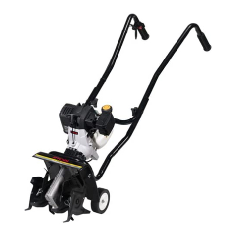
Frontier TR2058 User manual

OPERATOR’S MANUAL
AERATOR-OVERSEEDER
TR2058
Manual 5BP960374B
Date 08/07/2012

SAFETY
Take note! This safety alert symbol found throughout this manual is used to call your
attention to instructions involving your personal safety and the safety of others. Failure to
follow these instructions can result in injury or death.
Signal Words
Note the use of the signal words DANGER, WARNING and CAUTION with the safety messages. The
appropriate signal words for each have been selected using the following guidelines:
DANGER: Indicates an imminently hazardous situation that, if not avoided, will result in death or
serious injury.
WARNING: Indicates a potentially hazardous situation that, if not avoided, could result in death or
serious injury, and includes hazards that are exposed when guards are removed. It may also be used
to alert against unsafe practices.
CAUTION: Indicates a potentially hazardous situation that, if not avoided, may result in minor or
moderate injury.
This symbol means:
ATTENTION!
BECOME ALERT!
YOUR SAFETY IS INVOLVED!

40
7 - PRE-DELIVERY CHECKLIST
38
6 - TROUBLESHOOTING
375.05 - Storage 375.04 - Suggested Spare Parts 365.03 - Removing the Rotor 365.02 - Chain Case 365.01 - Gearbox 36
5 - REPAIR PROCEDURES
344.04 - Blade Maintenance 334.03 - Changing Rotors 314.02 - Service 304.01 - Maintenance Safety 30
4 - MAINTENANCE
273.21 - Transporting 273.20 - Uneven Terrain 263.19 - Working Limitations 263.18 - Headland Procedure 263.17 - Working Speed 263.16 - Working Depth 253.15 - Test Run 243.14 - Start Up 223.13 - Attaching to the Tractor 213.12 - Pre-Operational Check 213.11 - Safety Slip Clutch 203.10 - Driveline 183.09 - Seed (or Fertilizer) Hopper Calibration 163.08 - Hopper Adjustment 163.07 - Front Wheels Adjustment 153.06 - Front Roller Adjustment 143.05 - Corrugated Roller Adjustment 133.04 - Tickler Tine Adjustment 133.03 - Rear Tailgate Adjustment 123.02 - Set Up 103.01 - Operational Safety 10
3 - OPERATION
72.03 - Messages and Signs 72.02 - Starting and Stopping 62.01 - Preparation 6
2 - SAFETY PRECAUTIONS
51.03 - Model and Serial Number ID 41.02 - Warranty Information 41.01 - General 4
1 - GENERAL INFORMATION
INDEX
INDEX 3FRONTIER

1 - GENERAL INFORMATION
Thank you and congratulations for having chosen our implement. Your new
aerator-overseeder is a technologically advanced machine constructed of high quality,
sturdy components that will fulfill your working expectations.
The aerator-overseeder is the ideal machine for sport fields, parks, golf courses,
airports, turf farm operations and anywhere the combination of lower labor costs and a
professionally finished job is essential.
Read this manual carefully. It will instruct you on how to operate and service your
implement safely and correctly. Failure to do so could result in personal injury and/or
equipment damage.
1.01 - General
The implement described in this manual is to be used with tractors with PTO at 540 rpm
and clockwise rotation.
CAUTION: Always ensure that the coupling of the implement with the tractor is
done at the same PTO speed and direction of rotation. Do not operate this
implement at a PTO speed or direction of rotation other than that shown on the
implement. Serious damage can occur to the machine and/or the operator.
CAUTION: Unless otherwise specified, all hardware is metric. Use only metric
tools on metric hardware. Other tools that do not fit properly can slip and cause
injury.
CAUTION: Right hand and left hand sides of the implement are determined by
facing in the direction the implement will travel when going forward (see fig. 2).
1.02 - Warranty Information
Warranty coverage is provided by John Deere according to the terms of the
Agricultural/Commercial & Consumer Equipment Warranty Statement. Carefully read
the warranty statement on the back of your original purchase order for details on
coverage and limitations of this warranty.
Your Authorized Company Dealer has genuine parts in stock. Only these approved
replacement parts should be used.
AERATOR-OVERSEEDER OPERATOR’SMANUAL
GENERAL INFORMATION 4FRONTIER

1.03 - Model and Serial Number ID
Attached to the frame is an ID plate showing the model and the serial number. Record
your implement model and serial number in the space provided below. Your dealer
needs this information to give you prompt, efficient service when you order parts.
AERATOR-OVERSEEDER OPERATOR’SMANUAL
GENERAL INFORMATION 5FRONTIER

2 - SAFETY PRECAUTIONS
Safety is the primary concern in the design and manufacture of our products.
Unfortunately our efforts to provide safe equipment can be wiped out by a single
careless act of an operator.
In addition to the design and configuration of equipment, hazard control and accident
prevention are dependent upon the awareness, concern, prudence and proper training
of personnel involved in the operation, transport, maintenance and storage of
equipment. It is the operator’s responsibility to read and understand all safety and
operating instructions in the manual and to follow these.
Allow only properly trained personnel to operate the implement. Working with unfamiliar
equipment can lead to careless injuries. Read this manual, and the manual for your
tractor, before assembly or operation, to acquaint yourself with the machines. It is the
implement owner’s responsibility, if this machine is used by any person other than
yourself, is loaned or rented, to make certain that the operator, prior to operating, reads
and understands the operator’s manuals and is instructed in safe and proper use.
2.01 - Preparation
1. Before operating equipment read and understand the operator’s manual and the
safety signs (see fig. 2).
2. Thoroughly inspect the implement before initial operation to assure that all
packaging materials, i.e. wires, bands, and tape have been removed.
3. Personal protection equipment including hard hat, safety glasses, safety shoes, and
gloves are recommended during assembly, installation, operation, adjustment,
maintaining and/or repairing the implement.
4. Operate the implement only with a tractor equipped with an approved
Roll-Over-Protective-System (ROPS). Always wear your seat belt. Serious injury or
even death could result from falling off the tractor.
5. Clear area of stones, branches or other debris that might be thrown, causing injury
or damage.
6. Operate only in daylight or good artificial light.
7. Ensure the implement is properly mounted, adjusted and in good operating
condition.
8. Ensure that all safety shielding and safety signs are properly installed and in good
condition.
9. Consult local utility companies to make certain there are no buried gas lines,
electrical cables, etc., in the work area before beginning operation.
SAFETY PRECAUTIONS 6FRONTIER
AERATOR-OVERSEEDER OPERATOR’SMANUAL

2.02 - Starting and Stopping
1. Be sure that no one is near the machine prior to engaging or while the machine is
working.
2. Be sure the tractor is in “Neutral” before starting engine.
3. Equipment operating power is supplied from tractor PTO. Refer to your tractor
manual for PTO engagement and disengagement instructions. Always operate PTO
at 540 rpm. Know how to stop the tractor and implement quickly in case of an
emergency.
4. When engaging PTO, the engine rpm should always be low. Once engaged and
ready to start cutting, raise PTO speed to 540 rpm and maintain throughout cutting
operation.
5. Check the tractor master shield over the PTO stub shaft. Make sure it is in good
condition and fastened securely to the tractor. Purchase a new shield if old shield is
damaged or missing.
6. After striking an obstacle, disengage the PTO, shut the tractor down and thoroughly
inspect for damage before restarting.
7. Never engage the PTO until the implement is in the down position and resting on the
ground. Never raise the implement until the rotor has come to a complete stop.
8. To park the vehicle safely, stop vehicle on a level surface (not on a slope),
disengage PTO, engage the parking brake, stop the engine, remove the key, and
wait for engine and all moving parts to stop before leaving the operator’s seat.
9. Stay clear of rotating drivelines. Entanglement in rotating driveline can cause serious
injury or death. Wear close fitting clothing. Stop the engine and be sure PTO
driveline is stopped before getting near it.
2.03 - Messages and Signs
1. Read and adhere to all safety and operating decals on this machine (see fig. 2).
2. Before dismounting tractor: Allow moving parts to stop, stop engine, set brake and
remove the key of unattended equipment.
3. Keep away from rotating blades and driveline.
4. Keep guards and shields in place and in good condition.
5. Do not use with bystanders in area.
6. Allow no riders on tractor or implement.
7. Allow moving parts to stop before repair.
8. Securely support implement before working underneath.
Additional warning and operating decals are available at no extra charge. Please specify
model and serial number when ordering.
SAFETY PRECAUTIONS 7FRONTIER
AERATOR-OVERSEEDER OPERATOR’SMANUAL

Fig. 2 - Safety decals - implement; replace immediately if damaged.
SAFETY PRECAUTIONS 8FRONTIER
AERATOR-OVERSEEDER OPERATOR’SMANUAL
right side
left side
Red reflective decal
right side
left side

Safety decals - driveline; replace immediately if damaged.
SAFETY PRECAUTIONS 9FRONTIER
AERATOR-OVERSEEDER OPERATOR’SMANUAL
placed on outer shield
placed on outer tube

3 - OPERATION
The aerator-overseeder is a one pass tool which aerates, seeds (or broadcasts
fertilizes), levels, and compacts the soil for improved seed germination.
It consists of an aerator rotor with straight blades on narrowly spaced flanges, powered
by the tractor PTO. A large capacity seed hopper with precise metering cups is mounted
on the base aerator and broadcasts the seed behind the slicing action of the tines along
the entire working width of the machine. Tickler tines follow to help incorporate the seed
into the ground through compacted soil and thatch. A corrugated roller with fiberglass
rings follows behind the aerator-overseeder to compact the ground for optimal seed
germination.
Depth control wheels with wide garden style thread or a front roller may be quickly
mounted to ensure a constant depth over unleveled terrain.
The aerator-overseeder comes in working width of 58”.
A tilling rotor with “C” blades is available upon request, and may be mounted in place of
the straight blade aerator rotor. This converts the aerator-overseeder into a tiller for
seed bed preparation which tills, seeds and compacts the soil in a single pass.
Changing the machine over from an aerator to a tiller is a simple operation which can be
performed in under 30 minutes with a pair of wrenches.
This unique machine reduces costs for ground maintenance of sports fields, parks,
highways, hospital grounds, golf courses, etc. The aerator-overseeder can easily pay
for itself within the first few days of use.
3.01 - Operational Safety
CAUTION: Our machines are designed considering safety as the most important
aspect and are the safest available in today’s market. Unfortunately, human
carelessness can override the safety features built into our machines. Injury
prevention and work safety, aside from the features on our aerator-overseeder,
are very much due to the responsible use of the equipment. It must always be
operated prudently following with great care, the safety instructions laid out in
this manual.
1. The use of this equipment is subject to certain hazards which cannot be prevented
by mechanical means or product design. All operators of this equipment must read
and understand this entire manual, paying particular attention to safety and
operating instructions, prior to using.
2. Do not operate the tractor and implement when you are tired, sick or when using
medication.
OPERATION 10 FRONTIER
AERATOR-OVERSEEDER OPERATOR’SMANUAL

3. Before beginning operation, contact local utility companies to make certain there are
no bundled gas lines, electrical cables, etc., in the work area.
4. Keep all helpers and bystanders at least 50 yards from the machine. Only properly
trained people should operate this machine.
5. When this machine is operated in populated areas where thrown objects could injure
persons or property, standard equipment safety shielding (which is designed to
reduce the possibility of thrown objects) must be installed.
6. The majority of accidents involve entanglements on the driveline, injury of
bystanders by objects thrown by the rotating blades, and operators being knocked
off the tractor by low hanging limbs and then being run over by the implement.
Accidents are most likely to occur with machines that are loaned or rented to
someone who has not read the operator’s manual and is not familiar with the
implement.
7. Always stop the tractor, set brake, shut off the tractor engine, remove the ignition
key, lower implement to the ground and allow implement blades to come to a
complete stop before dismounting tractor. Never leave equipment unattended with
the tractor running.
8. Never place hands or feet under implement with tractor engine running or before you
are sure all motion has stopped. Stay clear of all moving parts.
9. Do not reach or place yourself under equipment until it is blocked securely.
10.Do not allow riders on the implement or tractor at any time. There is no safe place
for riders.
11.Do not operate unless all personnel, livestock and pets are 50 yards away to prevent
injury by thrown objects.
12.Before backing up, disengage the implement and look behind carefully.
13.Install and secure all guards and shields before starting or operating.
14.Keep hands, feet, hair and clothing away from moving parts.
15.This rotary implement is designed for use only on tractors with 540 rpm power take
off.
16.Never operate tractor and implement under trees with low hanging limbs. Operators
can be knocked off the tractor and then run over by the rotating blades.
17.The rotating parts of this machine have been designed and tested for rugged use.
However, they could fail upon impact with heavy, solid objects such as steel guard
rails and concrete abutments. Such impact could cause the broken objects to be
thrown outward at very high velocities. To reduce the possibility of property damage,
serious injury, or even death, never allow the cutting blades to contact such
obstacles.
18.Frequently check implement blades. They should be sharp, free of nicks and cracks
and securely fastened.
19.Stop implement immediately upon striking an obstruction. Turn engine off, remove
key, inspect and repair any damage before resuming operation.
20.Stay alert for holes, rocks and roots in the terrain and other hidden hazards. Keep
away from drop-offs.
21.Use extreme care and maintain minimum ground speed when transporting on
hillside, over rough ground and when operating close to ditches or fences. Be careful
when turning sharp corners.
OPERATION 11 FRONTIER
AERATOR-OVERSEEDER OPERATOR’SMANUAL

22.Reduce speed on slopes and sharp turns to minimize tipping or loss of control. Be
careful when changing directions on slopes. Do not start or stop suddenly on slopes.
Avoid operation on steep slopes.
23.When using a unit, a minimum 20% of tractor and equipment weight must be on
tractor front wheels. Without this weight, tractor could tip over, causing personal
injury or death. The weight may be attained with a front end loader, front wheel
weights, ballast in tires or front tractor weights. When attaining a minimum 20% of
tractor and equipment weight on the front wheels, you must not exceed the ROPS
weight certification. Weigh the tractor and equipment. Do not guess or estimate!
24.Inspect the entire machine periodically1. Look for loose fasteners, worn or broken
parts, and leaky or loose fittings.
25.Use only the driveline supplied with the implement. Do not use it if it is missing any
shield or safety protection.
26.Pass diagonally through sharp dips and avoid sharp drops to prevent “hanging up”
tractor and implement.
27.Avoid sudden starts and stops while traveling up or downhill.
28.Always use down slopes; never across the face. Avoid operation on steep slopes.
Slow down on sharp turns and slopes to prevent tipping and or loss of control.
3.02 - Set Up
Notice to dealer: Pre-delivery setup and service including lubrication is the
responsibility of the authorized dealer. It is up to him to assure that the machine is in
perfect condition and ready to be used. It is his responsibility to ensure that the
customer is aware of all safety aspects and operational procedures for the implement.
He must also fill out the Pre-Delivery Checklist2prior to delivering the implement.
CAUTION: Stand clear of bands when cutting as they could be under sufficient
tension to cause them to fly loose. Take care in removing bands and wire. They
often have extremely sharp edges and cut very easily.
Although the machine usually arrives set up, ready to use, it is important to check
certain aspects of the machine before using it. Adjustments are normally necessary in
order to adapt the aerator-overseeder to work under a given condition.
Check the oil in the gearbox. The proper level should be between 1/2 and 2/3 full. Use 90
wt. or 140 wt. gear oil. Make sure the breather cap is clear and tight in the gearbox.
Check all hardware for tightness, especially the bolts holding the 3 point hitch3.
Grease the cross and bearings and the telescopic tubes of the driveline.
Ensure that the drive chains are well greased, both the tiller drive chain in the chain
housing on the left side (see fig. 16) as well as the roller chain which drives the hopper
OPERATION 12 FRONTIER
AERATOR-OVERSEEDER OPERATOR’SMANUAL

3See Table 4, page 29.
2See Chapter 7 - Pre-Delivery Checklist.
1See Chapter 4 - Maintenance.

on the right side of the machine (see fig. 15). Both drive chains are supplied with an
automatic chain tensioner.
Grease the rotor support (see fig. 15).
Make sure the hopper and seed cups are mounted correctly.
3.03 - Rear Tailgate Adjustment
The rear tailgate is especially important when using the tilling rotor in place of the
straight blade aerating rotor. Its purpose is to improve the pulverization of the soil as it is
tilled. It can be adjusted in various positions with the chain. The closer the tailgate is to
the rotor the more pulverized the soil will be. The rear tailgate also works as a shield to
prevent dirt and other objects from being thrown (see fig. 3).
3.04 - Tickler Tine Adjustment
The aerator-overseeder comes with two rows of tickler tines mounted between the roller
arms (see fig. 4). These tines work as a rake to help cover grass seed for ideal
germination conditions. The tines are raised and lowered automatically as the roller
follows the contour of the ground.
The roller arms have two set positions to increase or decrease the tickler tine pressure.
When the tine holder is positioned in the lower hole the pressure is increased, the top
hole decreases the pressure. Always be sure both the right side and the left side are in
the same holes.
The tine holder bars can also be swiveled to increase or decrease the pressure of the
tines. This also enables you to maintain a consistent pressure and angle as the tines
wear. The bars can even be lifted completely up out of the way if the tickler tines are not
to be used.
OPERATION 13 FRONTIER
AERATOR-OVERSEEDER OPERATOR’SMANUAL
123
Fig. 3
2. chain
3. tailgate
1. chain hook

3.05 - Corrugated Roller Adjustment
The rear roller serves the following purposes:
1. Controlling the working depth.
2. Leveling the ground after tilling.
3. Compacting which results in helping bury the material that is distributed. The roller
rings help push seed into soil which greatly speeds up and improves germination.
A turnbuckle connected to the frame and to the roller support bar adjusts the working
depth of the tines.
By shortening the turnbuckle, the corrugated roller raises thereby lowering the tines to a
deeper working depth (see fig. 5). Lengthen the turnbuckle lowers the roller which in
turn raises the tines to a more shallow working depth.
Under most conditions, the working depth for the aerating rotor needs to be between
¾” and 1½” only, but the maximum obtainable depth is 7”.
OPERATION 14 FRONTIER
AERATOR-OVERSEEDER OPERATOR’SMANUAL
123
Fig. 4
1. roller arm
2. tickler tines
3. rear roller
1
2
3
4
Fig. 5
1. turnbuckle
2. seed tubes
3. roller arm
4. rear roller

If the machine is using a tilling rotor the working depth needs to be deeper depending
on the operator needs. The maximum working depth is 7”. An adjustable roller-scraper
bar is available upon request.
DANGER: Stay clear of rotating driveline. Entanglement in rotating driveline can
cause serious injury or death. Disengage PTO, engage parking brake or place
transmission in “Park”, shut off the tractor and remove the key before working
around hitch, attaching or detaching driveline, making adjustments, servicing or
cleaning the machine.
DANGER: Never trust the tractor hydraulics alone to support the machine. Never
do any repairs or adjustments under the machine unless it is safely blocked.
3.06 - Front Roller Adjustment
As an option, the aerator-overseeder can be supplied with a front roller. This option is
very useful when the machine is attached to the tractor three point in the float position.
This allows the machine to precisely follow the ground contour (see fig. 6).
The depth is controlled by turning the adjustment screws attached to each side of the
machine. When using, be sure both adjustment screws are in the same position.
The rear roller is then adjusted so the machine is working as level and parallel to the
ground as possible. The spikes welded to the front roller ensure constant contact with
the ground and prevent the roller from sliding along the ground and bulldozing.
OPERATION 15 FRONTIER
AERATOR-OVERSEEDER OPERATOR’SMANUAL
1
2
3
Fig. 6
1. adjustment screw
2. front roller
3. spikes

3.07 - Front Wheels Adjustment
Upon request the machine can be adapted with two front depth control gauge wheels
(see fig. 7) which are mounted on the side wheel support. These wheels have the same
function as the front roller, allowing the machine to follow the ground contour. They also
should be used with the tractor three point in the float position.
The depth is controlled by raising or lowering the wheels in the wheel supports attached
to the side of the aerator-overseeder. When using, be sure both wheels are in the same
position.
The rear roller is then adjusted so the machine is working as level and parallel to the
ground as possible.
3.08 - Hopper Adjustment
The aerator-overseeder hopper capacity is 5.30 cu.ft. The hopper runs the entire width
of the machine and has a continuously rotating ground driven agitator to breakup clods
and ensure free flow through the distribution system. On the bottom of the hopper are 8
OPERATION 16 FRONTIER
AERATOR-OVERSEEDER OPERATOR’SMANUAL
1
2
3Fig. 7
1. side plate
2. wheel support
3. front wheel
Fig. 8
Seed calibration handle

rectangular slots to allow material passage. The seed cups mounted under the hopper,
which are made entirely of non-corrosive material (nylon and fiberglass), contain an
internal gear that rotates inside a housing. A calibration handle located on the rear left
hand side of the hopper regulates how far to insert the gear inside the housing. The
position of the handle, which has a scale from 0 to 6, determines the amount of seed
distributed (see fig. 8). The seed cups are a force feed system driven by the roller.
The material is held inside the groove of the gear until the groove rotates to the opening
at the bottom of the hopper. This rotation is driven by the roller as it moves along the
ground. When the handle is in position “0” the gear is completely outside the seed cup
and no seed is distributed, with the handle in position “6” the gear is totally inside the
cup and distributes at its maximum potential (see fig. 8).
A secondary regulation is the lever located on the side of each cup housing. This
controls the position of the cleanout gate (top, middle, and bottom). Its position is
determined by the size and shape of the material being dispersed (see fig. 9). The top
position is for the smaller seeds, middle for the medium sized seed and bottom for
larger seeds. Attached to the bottom of each cup is flexible tubing that the material flows
through. As the material exits, it hits a split ring which divides the flow until it hits a
splash pan and uniformly spreads over the entire working width of the
aerator-overseeder.
The hopper is ground driven by the roller which comes with two separate chains with
automatic chain tensioners.
Although in essence a broadcast-seeder, the aerator-overseeder has all the technology
to ensure a precise calibrated flow. Being ground driven, the disbursement of the
material in the hopper is totally independent from the tractor PTO or the ground speed.
The disbursement is regulated solely by adjusting the seed cups levers and the hopper
lever.
OPERATION 17 FRONTIER
AERATOR-OVERSEEDER OPERATOR’SMANUAL
123
4
Fig. 9
1. seed cup
2. gear support
3. drive shaft bushing
4. seed cup regulation lever

3.09 - Seed (or Fertilizer) Hopper Calibration
There are two adjustments to be made to calibrate the aerator-overseeder hoppers:
1. The amount of gear inside the seed cup housing.
2. The position of the cleanout gate of each individual seed cup.
This system allows use of a wide variety of seeds.
The output of seed differs greatly depending on their size, density, dampness,
and shape. Other output factors depend on the conditions in which the machine is
operating such as, in slick conditions where the roller may slip.
Table 1 lists the distribution rate in pounds per acre for various seeds that may be used
in the aerator-overseeder. Keep in mind that the hopper and seed cup openings
measure in volume and not in weight. Due to the many variables, the distribution rate
when using Table 1 is not always accurate. Only a test run will help determine if the
desired amount of seed is being spread.
TABLE 1 - AMOUNT OF SEED DISTRIBUTED IN LB/ACRE
5234844323933533022652251741409644
Vetch
66961755150045038233028021316111043
Alfalfa
50046441638034329425922318613910354
Lovegrass, Sand
53649844841037532528625020016312268
Lovegrass, Weeping
1421321191089884736348392814
Wheatgrass, Crested
1581451301171058976644836247
Wheatgrass, Western
4384063633303002572241931501188738
Bermuda (hulled)
224217194176155131109906343250
Buffalo grass
57253047443238933429125019415111051
Clover, Red
69764457552347140135029722817612354
Clover, White
210206194176158134114957152304
Fescue K-31
26124121519617714912810983624316
Fescue, fine blade turf type
375346309281252214187158120926427
Ryegrass, Perennial
341315279254228193166140105795419
Ryegrass, Annual
22321219417816113812210581614318
Bluegrass, Kentucky
306290268251230202182156124897134
Bentgrass
65.554.543.532.521.510.5 Calibration handle positionSeed type
Use Table 2 and 3 to determine if the rate you are getting is correct.
There are two ways of setting the calibration on your aerator-overseeder:
1. With the machine stopped and raised, or
2. With the machine attached to the tractor and working.
To set the calibration with the machine stopped, do the following:
1. Support the machine securely, but in a way to allow the roller to turn freely.
2. Fill the hopper with the seed or fertilizer you intend to spread.
OPERATION 18 FRONTIER
AERATOR-OVERSEEDER OPERATOR’SMANUAL

3. Make sure the seed cups are not plugged with leaves, grass or other obstacles and
that the seed cup regulation levers are all adjusted to the same opening position.
4. Remove the seed tubes from the lower bar and attach bags to the ends to allow the
material to be collected.
5. Move the calibration handle located in the rear of the hopper to a position between 1
and 6 (see fig. 8).
6. Turn the roller by hand in complete turns for a minimum of 20 turns. The greater the
number of turns the more accurate the measurement will be.
7. Gather up and weigh all the material distributed in the bags. Divide this by the
number of turns the roller made. This will give the amount of material dispersed per
turn of the roller.
8. Each roller revolution, on the TR2058, corresponds to a surface area of 13.88
square feet therefore 72 revolutions equal to 1,000 square feet and 3,137 roller
revolutions equal to 1 acre. To obtain the amount of seed spread per acre, multiply
the quantity obtained with each revolution by 3,137 (see Table 2).
9. If the results do not correspond to the desired amount which needs to be distributed,
adjust the calibration handle accordingly.
TABLE 2 - WORKING SURFACE
72 revolutions = 1000 sq. ft.
3137 revolutions = 1 acre
1 revolution = 13.88 sq. ft.
TR2058
To calibrate the aerator-overseeder while it is working, do the following:
1. Measure out a predetermined distance on the ground (for example 200 linear feet),
keeping in mind that the further the distance, the more precise the measurement.
2. Fill the hopper with the seed you intend to spread.
3. Make sure the seed cups are not plugged with leaves, grass or other obstacles and
that the seed cup regulation levers are all adjusted to the same opening position.
4. Remove the seed tubes from the lower bar and attach bags to the ends to allow the
material to be collected.
5. Move the calibration handle located in the rear of the hopper to a position between 1
and 6.
6. Drive the tractor forward pulling the machine along the predetermined distance. It is
important for the roller to remain on the ground at all times and to roll continuously.
7. Collect all material distributed and weigh.
8. Using Table 3 determine the amount of material distributed. Example: If the
distance traveled is 100 ft. and 0.1 lb. of material is collected, then 9.2 lb. per
acre of material is being distributed.
9. If the results do not correspond to the amount that needs to be distributed, adjust the
calibration handle accordingly.
OPERATION 19 FRONTIER
AERATOR-OVERSEEDER OPERATOR’SMANUAL

TABLE 3 - AMOUNT OF MATERIAL DISTRIBUTED IN LB/ACRE
91.5101.7114.5130.8152.6183.2228.9305.2457.9915.7
10
87.096.6108.8124.2145.0174.0217.4290.0435.0869.9
9.5
82.491.6103.1117.7137.4164.8206.0274.7412.1824.1
9
77.886.597.3111.2129.7155.7194.6259.4389.2778.3
8.5
73.281.491.6104.7122.1146.5183.1244.2366.3732.6
8
68.776.385.998.1114.4137.4171.7228.9343.4686.8
7.5
64.171.280.191.6106.8128.2160.2213.7320.5641.0
7
59.666.274.485.099.2119.0148.8198.4297.6595.2
6.5
55.061.168.778.591.5109.9137.4183.2274.7549.4
6
50.455.962.971.983.9100.7125.9167.9251.8503.7
5.5
45.850.957.265.476.391.5114.5152.6228.9457.9
5
41.245.851.558.968.782.4103.0137.3206.1412.0
4.5
36.640.745.852.461.173.391.6122.1183.2366.3
4
32.135.640.045.853.464.180.1106.8160.3320.5
3.5
27.530.534.339.345.855.068.791.5137.3274.7
3
22.925.528.632.738.245.857.376.3114.4229.0
2.5
18.320.422.926.230.536.645.861.191.5183.1
2
13.715.217.119.622.827.534.445.868.7137.4
1.5
9.210.111.413.015.318.322.830.445.891.6
1
4.55.05.76.57.69.211.415.322.845.7
0.5
0.80.91.11.21.51.92.33.14.6
9.2
0.1
1,000900800700600500400300200
100 Distance traveled in feetLb. collected
all seed cups
3.10 - Driveline
DANGER: Only use the original driveline supplied with this machine and always
with the safety shielding. Carefully read and file away the driveline operator’s
manual supplied by the manufacturer. The following does not substitute the
information found in the driveline manual.
IMPORTANT: Always check driveline length during initial setup and when connecting to
a different tractor.
In the collapsed position the driveline should be approximately 2” from bottoming out to
prevent possible damage to the tractor or implement. When the driveline is in the
maximum extended position, the ideal minimum overlap of the two halves should be
approximately 6” (see fig. 10).
OPERATION 20 FRONTIER
AERATOR-OVERSEEDER OPERATOR’SMANUAL
Table of contents
Other Frontier Tiller manuals