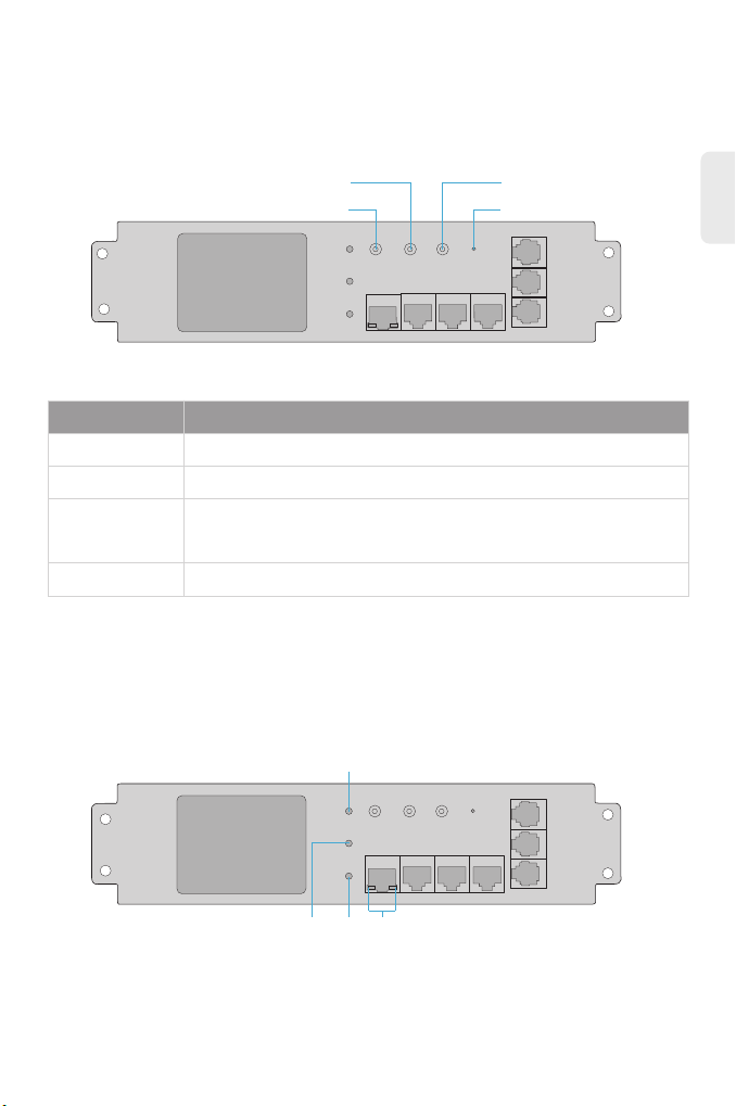
FS PDU-L6324I-VSW User manual

0U SWITCHED PDU POWER STRIPS
Quick Start Guide
0HE SWITCHED PDU-STECKDOSENLEISTEN
BANDES D'ALIMENTATION PDU A COMMUTATION 0U
0U スイッチ付 きPDU電 源タップ
V1.0
Quick-Start Anleitung
Guide de Démarrage Rapide
クイックスタートガイド

EN
1
PDU-L6324I-VSW
PDU-3PNE24I-VSW
Thank you for choosing the 0U Switched PDU Power Strips. This guide is designed to
familiarize you with the layout of the PDU strips and describes how to deploy them in your
network.
Introduction

EN
2
Accessories
Hardware Overview
Front Panel Ports
PDU-3PNE24I-VSW/PDU-L6324I-VSW
Ports Description
NET A port for 10/100M Ethernet connection
A serial port supporting the MODBUS access protocol
A cascade port for connecting the OUT port of the previous MPDU
A cascade port for connecting the IN port of the next MPDU
Ports for the temperature/humidity sensor connection
An audible and visual alarm port
SER
IN
OUT
T/H
Alarm
NET SER IN OUT
MPDU
RUN KWh ALM
NET UP
DOWN
SER
CONTROL
RESET
IN
OUT
Alarm
Alarm
T/H
T/H
T/H
NOTE:The accessories may vary from illustration, please prevail in kind.
M6 Screw x4 Network Cable x2 DB9 Serial Cable x1 Mounting Bracket x2

NET
EN
3
PDU-3PNE24I-VSW/PDU-L6324I-VSW
Front Panel Buttons
Front Panel LEDs
Buttons Description
UP A button for scrolling up to the previous page.
A button for scrolling down to the next page.
· Press to view the PDU status and conguration.
· Restore to factory settings: Press the CONTROL button, then press
the RESET button.
A button for restarting the device.
DOWN
CONTROL
RESET
CONTROL
RESET
UP
DOWN
MPDU
RUN KWh ALM
NET UP
DOWN
SER
CONTROL
RESET
IN
OUT
Alarm
ALM
KWH RUN
MPDU
RUN KWh ALM
NET UP
DOWN
SER
CONTROL
RESET
IN
OUT
T/H2
T/H1 Alarm T/H2
T/H1

EN
4
LEDs
RUN
ALM Alarm indicator Flashing when the threshold is exceeded.
The ashing frequency depends on the
connected load.
Flashing every second.
·On: The port is connected at 10/100M.
·O: The port is not connected.
Energy pulse indicator
Run indicator
10/100M connection
indicator
KWh
NET
LEDs Function Description
Installation Requirement
Site Environment
The PDU is for indoor use only.
Install and store the PDU in a dry and well-ventilated place. Ensure that the site is free from
direct sunlight and humidity.
Do not install any electric devices or PDUs during a thunderstorm.
Ensure that the PDU voltage is consistent with the local one.
Ensure that the maximum power of all devices is less than the PDU's.
The PDU sockets can only be compatible with the matched plugs.
PDU Maintenance
Disconnect the power and the network before disassembling or repairing the PDU.
Check if the fuses are blown regularly.
Check and clean the panels and inside of the PDU. Replace or clean the panels after
long-term use or if there is dust and dirt in the environment.
Check if the screws on the PDU are loose or lost regularly.
Check if the power rating matches the network load.
When maintaining the PDU, any changes or repairs made shall be documented.
When replacing the PDU spare parts, please follow the three steps: conrm the spare
parts you need to replace; prepare the necessary tools and materials and replace the
spare parts.

EN
5
Mounting the PDU
Rack Mounting
1. Remove the mounting pegs on the back of the PDU.
Toolless Mounting
Align both mounting pegs to the slots of the PDU bracket. Insert and slide down the PDU to
lock it rmly into place.

EN
6
2. Secure the vertical mounting brackets to the two ends of the PDU with screws.
3. Install the PDU on the rack with screws.

EN
7
Connecting the NET Port
Connecting the T/H Ports
Connect one end of the patch cable to the NET port on the front of the PDU, and the other end
to a network port of a PC or KVM.
Plug one end of the cable into the T/H port and the other end into the RJ45 port of a tempera-
ture/humidity sensor. Then you can monitor the temperature and humidity data via the Web
interface.

EN
8
Connecting the Power
1. Plug the PDU into a compatible UPS system or wall receptacle.
2. Plug the power cord into the power port of switches, servers, routers or other devices.
NOTE: Do not exceed the maximum connected load of the PDU.

EN
9
Cascading Connection
Network Port Protocol Hand-in-Hand Cascade
3. Connect the other end to the outlet of the PDU.
1. Log in to the Web access control interface of each device, and set one PDU as the host and
the others as slaves in the Working Mode of the Device Management.
NOTE: The outlets of switched PDU come with an anti-fall buckle, which
prevents the power cord from falling o.
OUT IN SER NET
OUT IN SER NET
OUT IN SER NET
OUT IN SER NET
MPDU1 MPDU2 MPDU3 MPDU4

EN
10
Network Port Protocol Bus Cascade
2. Connect an external network or LAN network cable to the NET port of the host PDU.
3. Connect one end of the network cable to the OUT port of the host, and the other end to
the IN port of the slave. Connect a network cable from the OUT port of the current slave to
the IN interface of the next slave.
4. Log in to the host system through a PC to monitor and manage the device.
Connect an external network or LAN network cable to the NET port of the HUB. Connect the
PORT port of the HUB to the NET port of each device. The number of bus cascades is
unlimited.
NOTE: 1. A host can cascade up to three slaves.
2. The network port protocol hand-in-hand cascade only supports the devices of the
same type and series.
OUT IN SER NET
MPDU1
PORT1NET
OUT IN SER NET
MPDU2
PORT2
OUT IN SER NET
MPDU3
PORT3
OUT IN SER NET
MPDU4
PORT4
HUB
......
......

EN
11
Serial Port Protocol Bus Cascade
Serial Port Protocol Hand-in-Hand Cascade
1. Log in to the Web access control interface of each device, and congure the serial port
communication address code in the Modbus Address Code of the Device Management.
2. Connect the RS-485 serial cable to the SER port of the device. According to the Modbus
RTU protocol, the host sends serial port commands to access.
NOTE: The maximum number of devices for the bus cascade is 32.
......
MPDU1
OUT IN SER NET
MPDU2
OUT IN SER NET
OUT IN SER NET
MPDU3
OUT IN SER NET
MPDU4
OUT IN SER NET
OUT IN SER NET
OUT IN SER NET
OUT IN SER NET
MPDU1 MPDU2 MPDU3 MPDU32
Slave1 Slave2 Slave3 Slave32
......
......
......

EN
12
1. Log in to the Web access control interface of each device, and congure the serial port
communication address code in the Modbus Address Code of the Device Management.
2. Connect the RS-485 serial cable to the IN port of the host PDU. According to the Modbus
RTU protocol, the host sends serial port commands to access.
3. Connect one end of the network cable to the OUT port of the host, and the other end to
the IN port of the slave. Connect a network cable from the OUT port of the current slave to
the IN interface of the next slave. Connect 32 PDUs in this way sequentially.
NOTE: After setting the serial port protocol hand-in-hand cascade, the network
port protocol hand-in-hand cascade function will be invalid.

EN
13
Conguring the PDU
Online Resources
Step 1: Power on the computer and the PDU.
Step 2: Set the IP address of the computer to 192.168.1.x ("x" is any number from 1 to 254,
Step 3: Open the installed browser on your PC, and input the PDU's IP address
Step 4: When the login window appears, enter the default username and password,
http://192.168.1.163.
admin/admin. Then click Login.
NOTE: The IP address for all PDUs is 192.168.1.163 by default.
except 163).
Download https://www.fs.com/products_support.html
Help Center https://www.fs.com/service/fs_support.html
Contact Us https://www.fs.com/contact_us.html
Username:
Password:
Login
Welcome To MPDU

EN
14
Product Warranty
Warranty: The products enjoy a 1-year limited warranty against defects in materials
or workmanship. For more details about the warranty, please check at
https://www.fs.com/policies/warranty.html
1
Return: If you want to return the item(s), information on how to return can be found at
https://www.fs.com/policies/day_return_policy.html
except 163).

DE
15
PDU-L6324I-VSW
PDU-3PNE24I-VSW
Vielen Dank, dass Sie sich für die 0HE Switched PDU-Steckdosenleisten entschieden haben.
Diese Anleitung soll Sie mit dem Aufbau der PDU-Leisten vertraut machen und beschreibt, wie
Sie sie in Ihrem Netzwerk einsetzen.
Einführung

DE
16
Zubehör
Hardware-Übersicht
Ports an der Vorderseite
PDU-3PNE24I-VSW/PDU-L6324I-VSW
Ports Beschreibung
NET Ein Port für 10/100M-Ethernet-Verbindung
Ein serieller Port, die das MODBUS-Zugangsprotokoll unterstützt
Ein Kaskaden-Port zum Anschluss des OUT-Ports der vorherigen MPDU
Ein Kaskaden-Port zum Anschluss des IN-Ports der nächsten MPDU
Ports für den Temperatur-/Luftfeuchtigkeitssensor
Ein akustischer und optischer Alarm-Port
SER
IN
OUT
T/H
Alarm
NET SER IN OUT
MPDU
RUN KWh ALM
NET UP
DOWN
SER
CONTROL
RESET
IN
OUT
Alarm
Alarm
T/H
T/H
T/H
M6-Schraube x4 Netzwerk-Kabel x2 DB9 Seriell Kabel x1 Montagewinkel x2
HINWEIS: Wir können nicht garantieren, dass die dargestellten Abbildungen genau
mit den tatsächlichen Objekten übereinstimmen.

DE
17
PDU-3PNE24I-VSW/PDU-L6324I-VSW
Tasten an der Vorderseite
LEDs an der Vorderseite
Tasten Beschreibung
UP Eine Taste zum Zurückblättern auf die vorherige Seite.
Eine Taste zum Blättern auf die nächste Seite.
· Drücken Sie diese Taste, um den Status und die Konguration der PDU
anzuzeigen.
· Wiederherstellen der Werkseinstellungen: Drücken Sie die Taste
CONTROL und dann die Taste RESET.
Eine Taste, um das Gerät neu zu starten.
DOWN
CONTROL
RESET
CONTROL
RESET
UP
DOWN
MPDU
RUN KWh ALM
NET UP
DOWN
SER
CONTROL
RESET
IN
OUT
T/H2
T/H1 Alarm
ALM
KWH RUN
MPDU
RUN KWh ALM
NET UP
DOWN
SER
CONTROL
RESET
IN
OUT
T/H2
T/H1 Alarm
NET

DE
18
LEDs
RUN
ALM Alarmanzeige Blinkt, wenn der Schwellenwert überschritten wird.
Die Blinkfrequenz hängt von der angeschlossenen
Last ab.
Blinken im Sekundentakt.
· Ein: Der Port ist mit 10/100M verbunden.
· Aus: Der Port ist nicht verbunden.
Energie-Impulsanzeige
Betriebsanzeige
10/100M
Verbindungsanzeige
KWh
NET
LEDs Funktion Beschreibung
Installationsvoraussetzungen
Betriebsumgebung
Die PDU ist nur für die Verwendung in Innenräumen geeignet.
Installieren und lagern Sie die PDU an einem trockenen und gut belüfteten Ort. Stellen Sie
sicher, dass der Standort frei von direkter Sonneneinstrahlung und Feuchtigkeit ist.
Installieren Sie keine elektrischen Geräte oder PDUs während eines Gewitters.
Stellen Sie sicher, dass die Spannung der PDU mit der Spannung vor Ort übereinstimmt.
Stellen Sie sicher, dass die maximale Leistung aller angesteckten Geräte geringer ist als
die der PDU.
Die Steckdosen der PDU sind nur mit den passenden Steckern kompatibel.
Wartung der PDU
Trennen Sie die Stromversorgung und das andere Verbindungen, bevor Sie die PDU
zerlegen oder reparieren..
Prüfen Sie regelmäßig, ob die Sicherungen durchgebrannt sind.
Prüfen und reinigen Sie die Verkleidung und das Innere der PDU. Ersetzen oder reinigen
Sie die Platten nach längerem Gebrauch oder wenn Staub und Schmutz in der Umgebung
vorhanden sind.
Überprüfen Sie, ob die Schrauben an der PDU locker sind oder sich regelmäßig lösen.
Prüfen Sie, ob die Nennleistung mit der Netzlast übereinstimmt.
Bei der Wartung der PDU müssen alle vorgenommenen Änderungen oder Reparaturen
dokumentiert werden.

DE
19
Wenn Sie die Ersatzteile der PDU austauschen, befolgen Sie bitte die drei Schritte:
Bestätigen Sie die Ersatzteile, die Sie austauschen müssen; bereiten Sie die erforderli
chen Werkzeuge und Materialien vor und tauschen Sie die Ersatzteile aus.
Montage der PDU
Rack-Montage
Montage ohne Werkzeuge
Richten Sie beide Montagestifte auf die Schlitze der PDU-Halterung aus. Setzen Sie die
PDU ein und schieben Sie sie nach unten, um sie zu befestigen.
This manual suits for next models
1
Table of contents
Languages:
Other FS Power Strip manuals
Popular Power Strip manuals by other brands

Tripp Lite
Tripp Lite SS7415-15 owner's manual

Reelcraft Industries, Inc.
Reelcraft Industries, Inc. LG3040 123 9 operating instructions

Tripp Lite
Tripp Lite 93-1990 (200108029) product manual

Tripp Lite
Tripp Lite 6SP Specification sheet

Tripp Lite
Tripp Lite TLM626NS Specifications

Tripp Lite
Tripp Lite PS-415-HG-OEM Specifications