4
2.0 OPERATION
NOTE:Installationsabove6000feet,1825meters
Unitisadjustedtooperateinaltitudesupto6000feet,
1825meters.Ifunitisinstalledinanaltitudeabovethis,
andhasnotbeenpresetatthefactoryforthisaltitude,
contactManufacturer’sServiceDepartment.
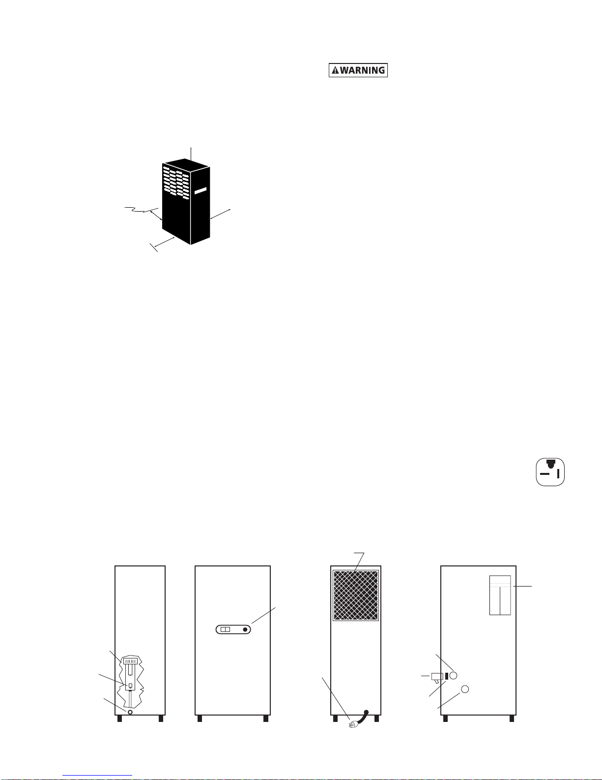
2.1 Start-up
Startrefrigerationsystembypushingtheon/offswitch
totheONposition(depressrockerswitchonsidemarked
“I”).
NOTE:Thefaultlightmayilluminatewhenunitisener-
gized.Lightshouldgooutapproximately5minutesafter
start-up.Iflightremainslitafter30minutesorillumi-
natesaftergoingout,refertoTroubleshootingGuide.
2.2 Operating check points
Checkthefollowingonaperiodicbasis:
A. RockerswitchisintheONposition.
B. Amberfaultlightisout.
C. Condensateisbeingregularlydischarged.
2.3 Minimum/maximum operating conditions
A. Minimum/Maximumairpressure:20/250psig,
1.4/17.6kgf/cm2
B. Maximuminletairtemperature:180°F,82°C
C. Minimum/Maximumambienttemperature:
40/110°F,4/43°C
ControlPanel
2. Fordryerswithanaftercoolerinstalledupstream
Flowcapacityinscfm(m3/min)@100°F,38°Cinlet
temperature,100°F,38°Cinletpressuredewpoint,
100°F,38°Cambienttemperature,50°F,10°Coutlet
pressuredewpoint,andlessthan10psi,0.7kgf/cm2
pressure drop.
D. Maximumowcapacity
1. Fordryerswithoutanaftercoolerinstalledupstream.
Flowcapacityinscfm(m3/min)@180°F,82°Cinlet
temperature,160°F,71°Cinletpressuredewpoint,
95°F,35°Cambienttemperature,50°F,10°Coutlet
pressuredewpoint,andlessthan5psi,0.35kgf/cm2
pressure drop.
I
O
On/Off Switch Fault Light
60 HZ
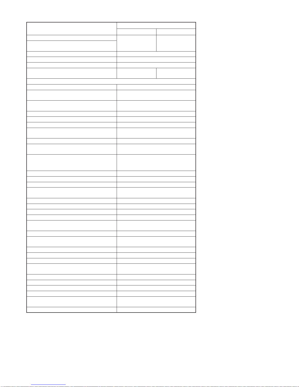
Inlet Pressure
psig (kgf/cm2)175 (12.3) 150 (10.6) 125 (8.8) 100 (7.0)
Model
20 23 (0.65) 22 (0.62) 20 (0.57) 18 (0.51)
25 29 (0.82) 27 (0.76) 25 (0.71) 23 (0.65)
35 41 (1.16) 38 (1.08) 35 (0.99) 32 (0.91)
50 58 (1.64) 54 (1.53) 50 (1.42) 45 (1.27)
75 87 (2.46) 81 (2.29) 75 (2.12) 68 (1.93)
100 116 (3.29) 108 (3.06) 100 (2.83) 91 (2.58)
125 145 (4.12) 135 (3.82) 125 (3.54) 114 (3.23)
50 HZ
Inlet Pressure
psig (kgf/cm2)175 (12.3) 150 (10.6) 125 (8.8) 100 (7.0)
Model
20 20 (0.57) 18 (0.51) 17 (0.48) 15 (0.42)
25 24 (0.68) 23 (0.65) 21 (0.59) 19 (0.54)
35 31 (0.88) 29 (0.82) 27 (0.76) 24 (0.68)
50 58 (1.64) 54 (1.53) 50 (1.42) 45 (1.27)
75 71 (2.01) 66 (1.87) 61 (1.73) 55 (1.56)
100 97 (2.75) 90 (2.55) 83 (2.35) 76 (2.15)
125 121 (3.43) 112 (3.17) 104 (2.95) 95 (2.69)
60 HZ
Inlet Pressure
psig (kgf/cm2)175 (12.3) 150 (10.6) 125 (8.8) 100 (7.0)
Model
20 32 (0.91) 30 (0.85) 28 (0.79) 25 (0.71)
25 40 (1.13) 37 (1.05) 34 (0.96) 31 (0.88)
35 55 (1.56) 51 (1.44) 47 (1.33) 43 (1.22)
50 78 (2.21) 73 (2.07) 67 (1.90) 61 (1.73)
75 118 (3.34) 110 (3.12) 102 (2.89) 92 (2.61)
100 157 (4.45) 146 (4.14) 136 (3.85) 123 (3.48)
125 197 (5.58) 183 (5.18) 170 (4.82) 155 (4.39)
50 HZ
Inlet Pressure
psig (kgf/cm2)175 (12.3) 150 (10.6) 125 (8.8) 100 (7.0)
Model
20 27 (0.76) 25 (0.71) 23 (0.65) 21 (0.59)
25 33 (0.93) 31 (0.88) 29 (0.82) 26 (0.74)
35 43 (1.22) 40 (1.13) 37 (1.05) 33 (0.93)
50 78 (2.21) 73 (2.07) 67 (1.90) 61 (1.73)
75 96 (2.72) 90 (2.55) 83 (2.35) 75 (2.12)
100 131 (3.71) 122 (3.46) 113 (3.20) 102 (2.89)
125 164 (4.65) 152 (4.31) 142 (4.02) 129 (3.65)