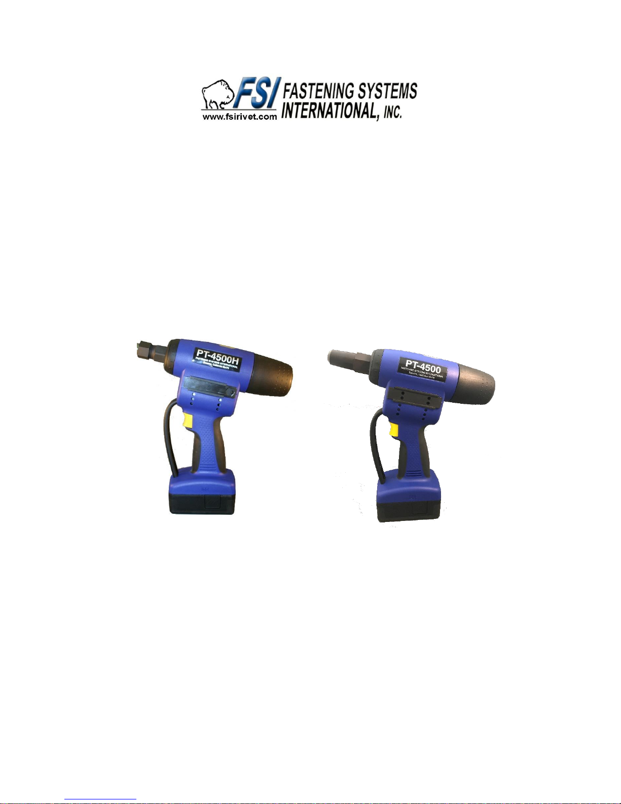
FSI PT-4500H User manual

PT-4500/PT-4500H
Operating Manual
Fastening Systems International, Inc
1206 E. MacArthur Street
Sonoma, CA 95476
Tel: 707-935-1170

Safety instructions
Caution:
The following safety rules must be observed for adequate protection against electric
shocks, injuries or fire hazards:
• The blind riveting tool should be used exclusively to set blind rivets!
• Do not overload the tool; work within the prescribed work capacity.
• Never use the blind riveting tool in a humid or wet environment or close to inflammable
substances or gases. Risk of explosion!
• Ensure that the battery is properly secured in the grip.
• Remove the battery when the blind riveting tool is not in use and for repair/servicing
operations.
• Do not use the blind riveting tool as a hammer.
• When not in use, keep the blind riveting tool in a dry, closed room and out of the reach
of children.
• When working with the tool, always wear protective goggles. Personal protection like
clothes, gloves, safety helmet, non-slip shoes, ear protection and anti-fall protection are
highly recommended.
• The air inlets for the motor should not be obstructed. Do not introduce anything into
them.
• When setting the blind riveting tool down, make sure that it cannot fall.
• Use only genuine spare parts for repair.
• Repair work must be carried out by skilled workers. In case of doubt, always send the
blind riveting tool back to the manufacturer.
• Do not use the tool outside of riveting holes! The blind rivet could be ejected from the
tool! Never turn the tool towards yourself or towards another person!
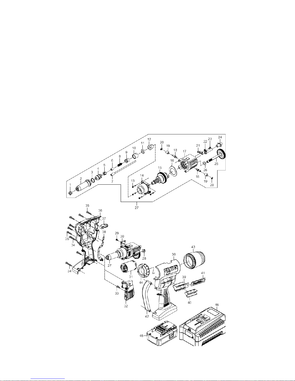
• The mandrel container (n° 39) must be mounted on the blind riveting tool during operation.
Starting procedure
• Insert fully charged battery in correct position into housing.
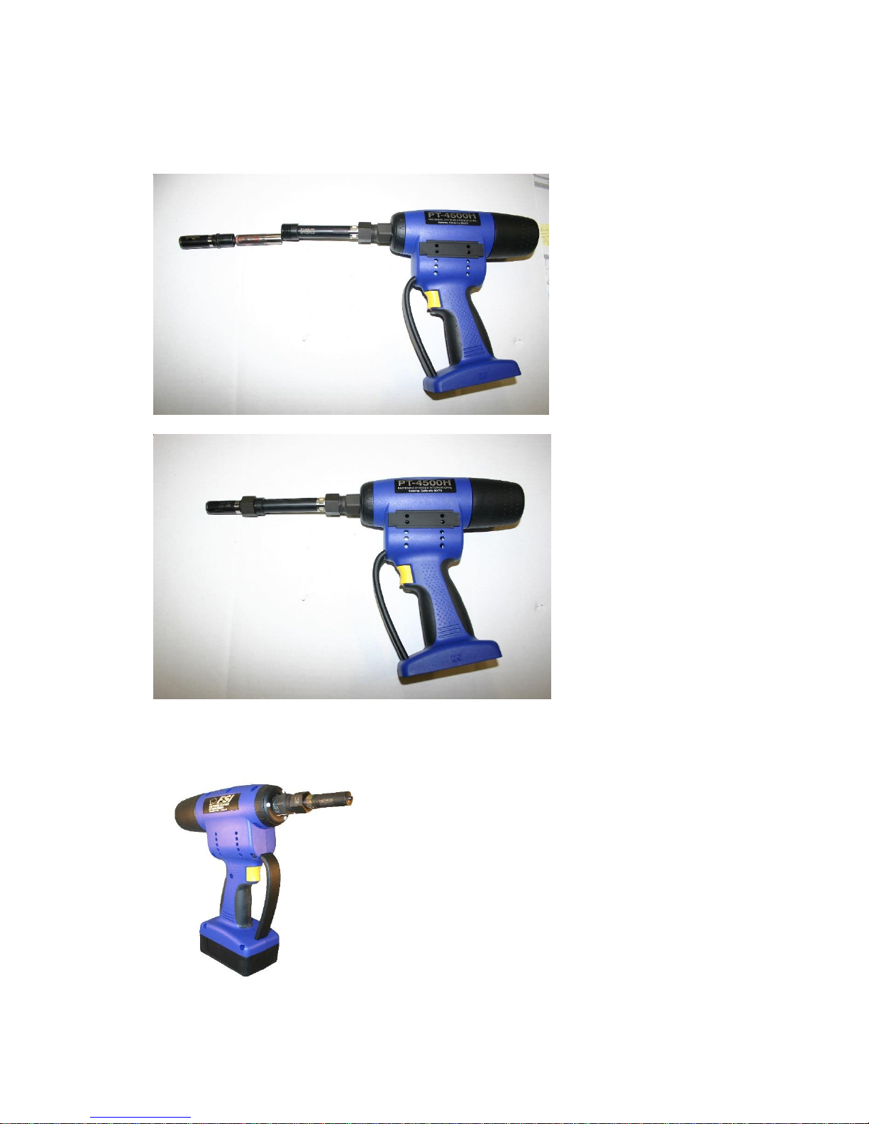
• Select correct nosepiece according to table 1.4.
• To screw in the nosepiece, activate the switch and proceed until the stop position has
been reached at the back.
• Then remove the battery. Screw in the nosepiece and tighten it using the wrench
provided. Put the battery back in and activate the switch.
Mode of operation
The blind riveting tool features optimized operating speed. After inserting the blind rivet, the
blind riveting tool can be operated in two different modes:
a. Pressing and holding the switch:
Press and hold the switch to start riveting. The pulling process stops automatically when the
rivet reaches the rear end position. The tool automatically assumes the front starting position
when the switch is released.
b. Tapping the switch:
Riveting is triggered by briefly tapping and immediately releasing the switch. As soon as

the mandrel breaks off, the blind riveting tool stops and automatically re-assumes the front
starting position.
• Eject the spent mandrel by tilting to the rear into the spent mandrel container or to the
front through the nosepiece.
• The blind riveting tool is equipped with overload protection. In the event of overloading
the blind riveting tool, e.g. by setting rivets that are outside the working range, riveting
stops, indicated by the 3 LEDs flashing slowly (1 Hz). Press the switch to make the blind
riveting tool go back to the start position and it is then ready for operation.
• The control detects a blockage on return (e.g. dirt, foreign object, etc. in the steel head
sleeve). The tool stops the return procedure and immediately assumes the rear end position
automatically. The fault is indicated by the LEDs flashing rapidly (2 Hz). The battery
pack must be removed and the fault eliminated. Then reinsert the battery and briefly
press the switch. The tool assumes the front-end position and is again ready for use.
• The blind riveting tool is fitted with an acoustic warning device, which provides information
about the remaining battery time. Beeps sound to tell the user when to change the battery.
This ensures that the blind riveting tool will not switch off during a riveting operation.
The blind riveting tool is equipped with 3 LED lights to illuminate the work space. These can
be turned on by turning the black ring (n° 44) behind the LEDs. There are 3 settings, which are
displayed by an arrow cast in the housing.
3 beeps and flashing LED lights for 10 seconds:
The battery needs to be changed soon (about 20% battery charge remaining).
6 beeps and flashing LED lights for 10 seconds after every setting sequence:
Change the battery after a few more riveting sequences in order to guarantee safe riveting
sequences (approx. 10% battery remaining).
9 beeps and flashing LED lights for 10 seconds: The next riveting sequence cannot be
reliably carried out. The blind riveting tool is switched off. Change the battery.
1.8 Lighting
—Continuous light/torch function:
The lighting is switched on after a riveting sequence and stays on for
approx. 10 minutes. The LEDs then turn off automatically.
Zero position:
Lights switched off.
-- Work light:
Lights are switched on at the start of the riveting sequence. The LEDs stay
on for about 10 seconds and then switch off automatically.

Maintenance
The maintenance of the blind riveting tool is limited to the complete claw mechanism and the
associated wearing parts:
• Remove battery (n° 55) from the blind riveting tool.
• Unscrew the head (part n° 13) using flat wrench SW 14 or SW 24 and clean. Look for
deposits in the top of the head!
• Unscrew the jaw housing (n° 15) using 2 SW 17 flat wrenches.
• Take out the jaws (n° 16) and jaw pusher (n° 17), clean them and lubricate or grease the
sliding surfaces; replace the jaws (n° 16) if worn (blunt teeth!).
• Re-assemble in reverse order ensuring that all parts are tightened! We recommend that
you secure the screw connection using a thread adhesive (such as Loctite 222 or Loctite
243).
Regular maintenance will extend the service life of your high-quality PT-4500 tools
and they should be serviced at least every 2 years by an authorized workshop or by
FSI Service. For tools that are used intensively, we recommend servicing ahead of
schedule.
Charger and battery
Technical data
Battery charger
Input voltage: 100 V-240 V~/50-60 Hz
Output voltage: 21 VDC
Output current: 2.5 A
Weight: 0.6 kg
Battery
Nominal voltage: 18.0 V
Number of cells: 5
Cell/capacity: Li-Ion; 2.1 Ah
Weight: Approx. 0.42 kg
Safety instructions
Battery charger
Caution:
The following safety rules must be observed for adequate protection against electric
shocks, injuries or fire hazards:
• The charger must be used exclusively to charge FSI batteries.
• Check the cord, plug and charger regularly and have them repaired by Service or by an
authorized skilled specialist electrician when damaged.
• For repairs, use only genuine plugs and cords and genuine spare parts.
• Never use the charger in a humid or wet environment or close to inflammable substances
or gases. Risk of explosion!
• Take the charger out of its packaging before use. Insert the FSI battery in the right
way into the charger.

• Never try to charge non-rechargeable batteries.
• Store the charger in a dry, closed room, out of the reach of children.
• Never insert metallic parts into the charging bay - danger of short circuiting.
• If the charger is wall-mounted, make sure that the inserted battery cannot fall out due to
external influences (e.g. vibrations).
• This battery charger should not be operated by people with physical or mental disabilities
or impairments, nor by untrained or unskilled persons. If this is the case, they should be
supervised by someone who is responsible for safety or receive instructions from them
as to how to use the device.
Battery
Caution:
The following safety rules must be observed for adequate protection against electric
shocks, injuries or fire hazards:
• Never insert metallic parts into the charging bay - danger of short circuiting.
• Never try to charge a damaged battery.
• Do not insert a dirty or wet battery into the charger.
• Never throw batteries into the waste, into fire or into water.
Charging procedure
• Charge only FSI batteries and when the temperature of the environment is
between -5°C and +55°C!
• Take the charger out of its packaging and connect to the mains.
• Gently insert the FSI battery in the right way into the charger.
• The charging operation starts automatically.
Function lights
Signal Meaning
Constant green Battery is charged / top-up charging
Flashing green Charging
Constant red Charging temperature out of range (battery too hot or too
cold)
Flashing red Battery is defective or wrong battery (different manufacturer)
Charging* takes approx. 40 minutes.
* Charging times may vary according to the remaining capacity and the battery temperature.
Battery handling
• Only insert batteries into the charger once they have cooled down.
• FSI batteries can be charged approx. 1000 times.
• Do not insert the battery into the charger after each use.
• If battery autonomy becomes significantly shorter despite proper recharging, the battery
should be replaced.
• Store batteries in a dry place where there is no danger of frost. The optimum operating
temperature range is 10°C to 50°C.
FSI batteries have a display showing battery life in percent. Press the button in the display
to activate the green LED lights for approx. 5 seconds.

***** Battery fully charged
**** Battery capacity approx. 80%
*** Battery capacity approx. 60%
** Battery capacity approx. 40%
* Battery capacity max. 20%, charge soon
Diagram:

Parts List: PT-4500
1
F159
1/8” Nosepiece
F156
3/32” Nut-plate Nosepiece
F143
5/32-3/16 Nosepiece
F142
1/4" Nosepiece
2
F130-F
Nose Tube
3
F6012
O-Ring
4
F126-F
Jaw Holder
5
F122-A
2-pc Jaws
6
F3245
Jaw Follower, ¼”
7
F3621A
Jaw Follower
8
F3081A
Jaw Follower Spring
9
F3605-1
Draw Bolt
10
F3185-1
Adapter Housing
11
F3745
Scraper Ring
12
Not Used on the PT-4500
13
F5768
Screw
14
F5398
Housing, Front
15
F5406
Ball Screw
16
F4962
Spacer Ring
17
F5397
Ball Screw Housing
18
F5385
Guides
19
F4970
Stand Off
20
F5790
C-Clip
21
F0817
Clip
22
F5393
Ejector Tube
23
F5990
Screw
24
F4874
Tail
25
F5395
Drive Gear
26
F4967
Spacer
27
F7643
Ball Screw - Complete
28
F5763
Stand Off
29
F5989
Screw
30
F5408
Stroke Adjustment Plate
31
F7645
Motor
32
F5381
E-Control
33
F5773
Screw
34
F5987
Screw, Long
35
F5772
Screw
36
F5401
Housing, PT-4500
37
F5746
Loop
38
F5403
Guide Arm
39
F5016
Not Included, Nosepiece
Holder

40
F4978
Rubber Insert, Not
Included
41
F7646
Wrench Cover
42
F5399
Handle Guard
43
F5396
Canister
44
F7644
LED Lights
45
F-4500A
18v Battery Pack, Li-Ion
46
F-3500A
Battery Charger, USA Plug
F-3500B
Battery Charger, EU Plug
PT-4500 Configurations:

PT-4500H Configurations:
1. Basic Tool –No Pulling Heads
2. Adding the F4187-AR-4500 –Rotating Adapter for Offset Huck Heads
3. Adding the F1458-SE –Side Ejection Adapter

4. Adding a Huck Pulling Head
5. Standard Configuration
This manual suits for next models
1
Other FSI Power Tools manuals
Popular Power Tools manuals by other brands

Bahco
Bahco TAWM1412M Original instructions

Bravura
Bravura A-1020 Installation & operational & instructions manual

ADENDORFF
ADENDORFF GCABSB-001 Operation manual and parts list

Parkside
Parkside PAT 12 B2 Operation manual

Schneider Airsystems
Schneider Airsystems RF-RMG Original operating manual

EINHELL
EINHELL 4321235 Original operating instructions