FSR INC. Eagle 200 User manual

Background, DSK, and LOGO Setup
2
1
SDI In Analog In BG/DSK In
Genlock Preview Out
Program Out
1
2
3
4
5
6
7
8
A
B
12
In Loop
Serial 1
Serial 2 Ethernet
100-240 V 50-60 Hz
2.3 A
Quick Install and Setup
ScreenPRO-II User’s Guide
For complete details on all installation and operations procedures,
please refer to the ScreenPRO-II User’s Guide.
* Breakout Cables for Analog Inputs
Breakout Cable
Wire Color Comp
Video S-Video
(Y/C) YUV
(YPbPr) RGB
Sync on Green RGB
Comp Sync RGB
Separate H V
R
G
B
H Sync
V Sync
(Chrom) (Pr)
(Lum) (Lum)
(Pb)
1. Observe all safety precautions. Rackmount chassis, or
install in “tabletop” configuration.
2. Connect all inputs, monitors, projector and AC. Install
genlock signal if required. Power on.
3. Perform factory reset: Using Touch Screen buttons,
press {SYSTEM} > {RESET}. On Reset Type line, use
ADJ knob to select FACTORY. Press {RESET} > {YES}.
4. Calibrate Touch Screen: Press {DISPLAY} >
{LCD CAL},and follow on-screen prompts.
Getting Started
Input Setup
12. On the Source Selection Bus, press an input button.
If the “acquire” is successful, the source appears on
Preview. This may take several seconds.
13. Press {SAVE}. The Input Menu will appear.
14. If the “Acquisition Failed” message appears, check
all connections and press {FORCE ACQUIRE}. If
successful, press {SAVE}.
15. If the input still does not acquire, perform a detailed
setup. [User’s Guide: Chapter 5, “Comprehensive
Input Setup” section.]
16. Repeat from step 12 for all remaining inputs. Be sure
to {SAVE} each input.
Note: To adjust input size, use the {SIZING} menu.
[User’s Guide: Chapter 4, “Sizing Menu” section.]
5. Press {OUTPUT}.
6.OnFormat line, select projector’s native resolution.
7. Press {SELECT FORMAT} to accept, then {SAVE}.
8. For projector setup, press {TEST PATTERN}.
9.OntheType line, select the Burst pattern.
Output and Projector Setup
17. See User’s Guide, Chapter 5 for setup procedures. DVI background
and DSK must be set at same resolution as system output.
10. Adjust your projector as required. [User’s Guide:
Chapter 5, “Projector Setup” section.]
11. When complete, set test pattern Type to Off, set
Raster Box to Off, then press {HOME}.
Analog Inputs
Connect to analog sources
such as PCs, VTRs, and
cameras. Use breakout
cables as required.
See * below for details.
Background / DSK
Inputs
Connect to DVI sources such
as PCs. Input B can be either
BG or DSK, but not both.
Backgrounds and DSK are
unscaled sources.
Serial 1
For downloading
firmware updates.
Genlock
Connect a reference
signal such as black burst
or composite sync.
Program Out Digital
Connect to projector. Program Out Analog
Connect to projector or analog
Program monitor.
Ethernet
For use with external
controller.
Preview Out
Connect to analog
Preview monitor.
AC
Connect to AC
power source.
SDI Inputs
On HD model only,
connect to SD-SDI
or HD-SDI sources.
Eagle 200
Quick Start Guide
TAKE A NEW LOOK
FSR Inc.
244 Bergen Boulevard
West Paterson, NJ
07424
Phone:
Fax:
Technical Support:
Website:
+1 (800) 332-3771
+1 (973) 785-3318
+1 (800) 332-3771
www.fsrinc.com
LIT 1119 D143897A

4
3
2
15678SDI
1
SDI
2
LAYER
B
LAYER
A
BG
BDSKLOGO
BG
AWIPECUT MIX
PIP
Full
Screen
KEY
Split
Layer
Clear
Layer
Swap
Z-Order FreezeReset Move
SetupMove
Program
Program
MixerFunctions
BackgroundMixer Transitions
Source Selection
MenuSystem Orientation
Operations OverviewImportant Global Rules
From the Home Menu, press:
{INPUT} > Input Menu.Set input format, adjust brightness &
contrast, adjust aspect ratio, set color balance, sizing
{OUTPUT} > Output Menu. Set outputformat, adjust genlock
params, set test patterns and output raster box
{SYSTEM} > System Menu. Set “mix mode” params,
software reset, diagnostics, program EDID, set com params
{EFFECTS} > Effects Menu. Set transition and wipe params
{STATUS} > Status Menu. Displaysoftware version
{DISPLAY} > DisplaySettings Menu. Set Touch Screen
brightness/contrast,button backlight, and LCD calibrate
{FRAME GRAB} > Frame Grab Menu. Grab still frames to
use as background, DSK or LOGO source
{REMOTE CONTROL} > RemoteControl Menu. Enable &
disable remote control.
Red LED: source or layer ison Program, but not adjustable
Blinking button:source or layeractive for modification
Solid button: source or layer on Preview, but notadjustable
Backgrounds,DSK andLOGO are unscaled sources.
Background B and DSK are mutually exclusive. If one is
on-air, the other cannot be used.
"Blinking"Raster Boxis the one enabled for modification.
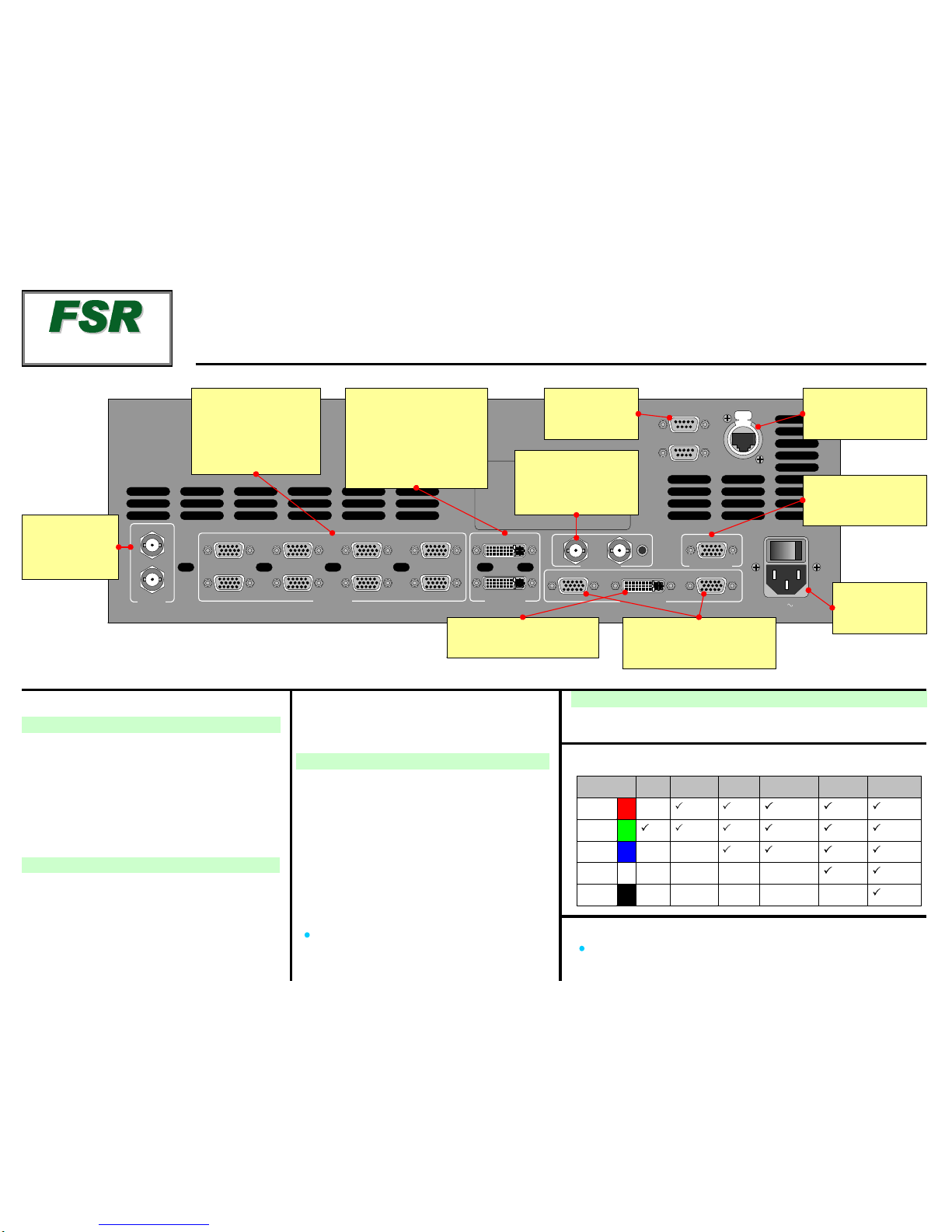
Button Color Usage
1
PIP
MIX
White:Sources
Yellow:Functions that
apply to active layer
Red: Transitions
Green:Unscaled sources
Blue:Scaled sources
LAYER
B
BG
A
Workingwith PIPsin Mix Mode
Alwayscompose your “look” on Preview. This represents the
exact appearanceof Program — after you transition.
1. OnSource Selection Bus,select an input.
2. PressPIP. The PIP Adjustment Menu appears.
3.(Optional) Press Full Screen.
4.Adjust PIP size, position, border, shadow, source image,
cropping and "special effects." [User’s Guide: Chapter 6,
“Modifying PIPs” section.]
5. Transition the setup to programby pressing WIPE,CUT or MIX.
[User’s Guide: Chapter 6, “Working with Transitions” section.]
6.For the next PIP setup, repeat from step 1.
7. To remove layerfrom Preview, press Clear Layer, and then
press WIPE,CUTor MIX to remove the layer from Program.
8. Forinformation on all operational modes and features, refer to
Chapter 6, “Operations”in the User’s Guide.
Use this list to learn what’s available on each menu
LayerControlSection
Choose combination of layers to
transitionto/from Program.Compose
the next“look”on Preview
Red LEDs
Indicatesourcesand
layerson Program
Source Selection Bus
Select thesource for the
active PIP or KEY
Transition Section
Press to start transition
from Preview to Program.
Use Effects Menuto set
transition parameters
Pend
“Move” on
active layer
Set up a
“Move” on
active layer
Reset current
parameter to
default
Freeze active
layer on Pgm,
Pvw
Change
layer
priority
Remove
activelayer
from Preview
Change
active layer
to a PIP
Eagle 200
INPUT OUTPUT SYSTEM EFFECTS
STATUS DISPLAY FRAME
GRAB
REMOTE
CONTROL
Rotary Knobs
NAV to navigate (select) lines
ADJ to adjust values
Touch Screen
{HOME} > Home Menu
{BACK} > Back onelevel
Take active
layer to full
screen
Change
activelayer
to a Key
Change
between
Split and
Mix Modes
Eagle 200
Quick StartGuide
TAKEA NEW LOOK
FSR Inc.
244 Bergen Boulevard
West Paterson, NJ
07424
Phone:
Fax:
Technical Support:
Website:
+1 (800) 332-3771
+1 (973)785-3318
+1 (800)332-3771
www.fsrinc.com
Table of contents
Popular Switch manuals by other brands

Allied Telesis
Allied Telesis AT-8600 Series Hardware reference

ProSoft
ProSoft MVI56E-AFC reference guide

TRENDnet
TRENDnet TPE-224WS - Web Smart PoE Switch Quick installation guide

REI
REI UHD-301C user manual

Moxa Technologies
Moxa Technologies PT-G7728 Quick installation guide

Extreme Networks
Extreme Networks 200 Series Installation and user guide

Electro Cam
Electro Cam Plus PS-6144 Series Programming & installation manual

ANTAIRA
ANTAIRA LNX-1204G-10G-SFP Hardware manual

Palmer
Palmer TRIAGE quick start guide

HomeMatic
HomeMatic HM-LC-Sw1-Ba-PCB Mounting instruction and operating manual

UTC Fire and Security
UTC Fire and Security interlogix IFS MCR205-1T user manual

Eaton
Eaton QSA400 Series Instruction leaflet