INNOVATIVE ENGINEERING AND QUALITY MANUFACTURING OF ELECTRONIC SWITCHING AND CONTROL PRODUCTS
244
Ber
gen
Boulevard,
W
est
Paterson,
NJ
07424
T
el
973-785-4347
Fax
973-785-3318
E-Mail
[email protected]AUDIO PRODUCT GROUP
FSFS
FSFS
FSRR
RR
Rinin
inin
incc
cc
c..
..
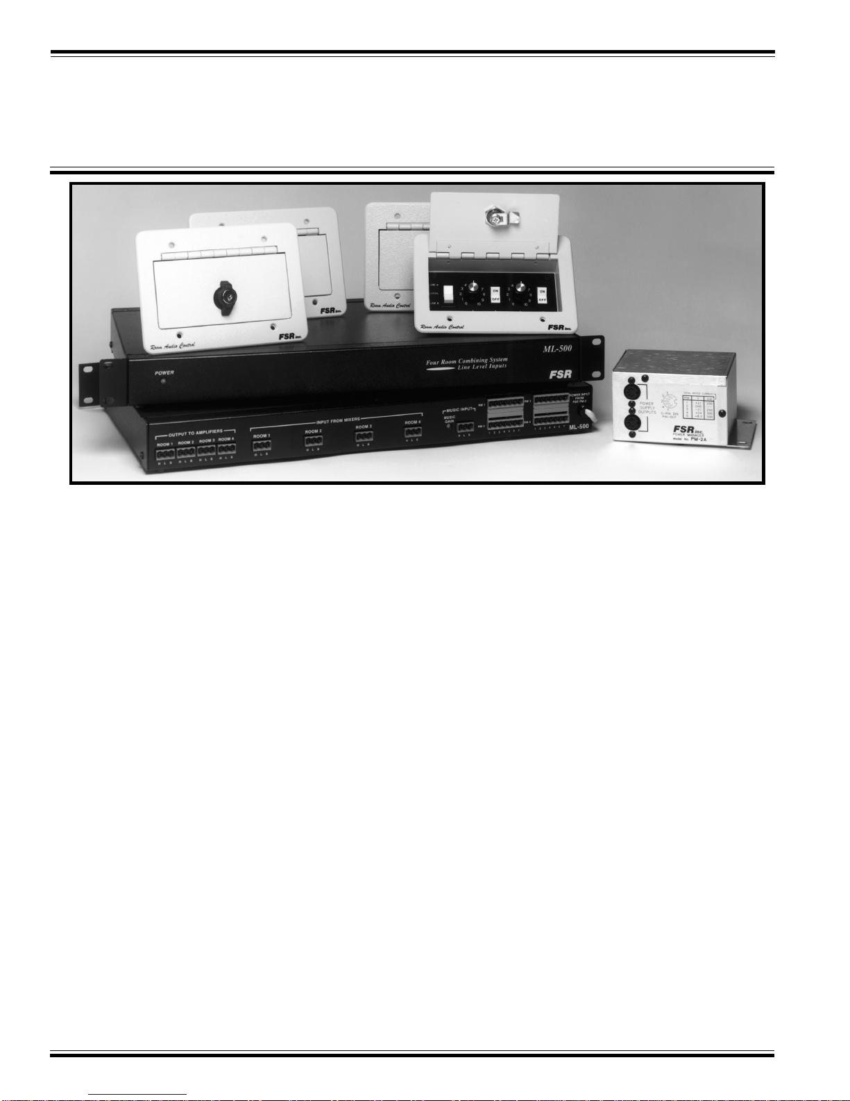
.ML-500
OPERATION and INSTALLATION
Ideal for smaller hotels and conference centers with
more stringent budget restraints, the ML-500 strikes a
goodbalanceinthebasicrequirementsofmicrophoneand
music control and the more elaborate features found in
ourlargercombiningsystems.
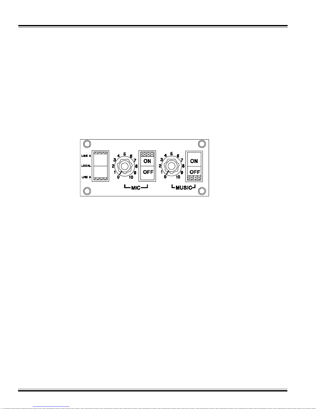
The system features in-room control plates to operate
microphone(onoroff),backgroundmusic(onoroff),a
combineswitchthatcanselectoneoftwotielinesorlocal,
anda volumecontrol forthemic andmusic audiolevels.
Efficientandfoolproofinstallationisassured. Thein-room,
3-gangwallplates have a7-wirecable thatconnectsviaa
pluggablescrewconnectortothemain control unit, and
power for the main unit is provided by a PM-2 power
supply.
System operation is easily understood and can be con-
trolled by the staff.
To combine two rooms, place each room’s combining
switch to Tieline A. The rooms are now mixed. For
backgroundmusicset the music volume controloneach
room'swallplatetothesame value,and select "musicon"
inbothrooms. Musicwillbe heardin bothroomsequally
loud.Theothertwo roomscouldbecombinedbyplacing
eachroomcombiningswitchtoTielineB.
If microphone operation is desired, the rooms could be
mixedas above, the microphone switch turnedon in all
mixedrooms(two in this example),andthensetthe vol-
umecontrolequallyinbothrooms,forathedesiredlisten-
inglevel.
If none of the rooms are combined, then each room’s
combining switch must be set on local. This allows
full control of each room’s audio from the wallplate.
All mixer inputs as well as the music input are elec-
tronically balanced. All audio outputs are balanced,
600 ohm, transformer-coupled outputs insuring
trouble-free installation.
There are two busses: Line A and Line B. Any
wallplate that selects either of these busses will have
its associated audio summed with any other wallplate
that selects the same line. Since this is a four-room
system (or less), only two busses are required to mix
rooms in any conceivable fashion.
THE ML-500 ROOM AUDIO
COMBINING SYSTEM