Fuego FM20AMG User manual

1
MODEL: FM20AMG (Modular)
PLEASE RETAIN THIS MANUAL FOR FUTURE REFERENCE.
•Do not operate the grill under unprotected combustible construction. Use only in well
ventilated areas. Do not use in buildings, garages, sheds, breezeways or other such
enclosed areas. This unit is for outdoor use only.
•This outdoor cooking gas appliance is not intended to be installed in or on recreational
vehicles and/or boats.
APR09
WARNING:
1. Do not store or use gasoline, or other
ammable liquids or vapors in the
vicinity of this or any other appliance.
2. An LP cylinder not connected for use
shall not be stored in the vicinity of
this or any other appliance.
DANGER
If you smell gas:
1. Shut off gas to the appliance.
2. Extinguish any open ame.
3. Open lid.
4. If odor continues, keep away from the
appliance and immediately call your
gas supplier or your re department.
FUEGO North America
Roundhouse One
1500 Sansome Street, Suite 100
San Francisco, CA 94111
415.558.7151 (local)
1.888.88.FUEGO (toll free)
www.fuegoliving.com

WARNING:
Improper installation, adjustment, alteration, service or maintenance can cause property
damage, injury or death. Read the installation, operating and maintenance instructions
thoroughly before using, installing or servicing this equipment. For outdoor use only.
3 Safety Practices & Precautions
Gas Requirements
6 General
7 LP Gas
8 Leak Testing
9 List of Included Materials
10 Dimensions
Assembly
11 Frame, Handles and Knobs
12 Modular Units
13 Light Unit and End Panels
14 Gas Connections
16 Drawer Installation and Grate Assembly
17 Battery Installation
18 Warming Drawer
19 Optional Charcoal Drawer
20 Utility Unit
21 Counter-Tops
Using the Grill
24 Grilling
25 Infrared Cooking
26 Burner Adjustments
Maintenance
27 Burner
28 Care & Cleaning
29 Cooking Tips
32 Troubleshooting
34 Accessories
35 Warranty
TABLE OF CONTENTS
2

IMPORTANT SAFETY NOTICE:
Certain Liquid Propane dealers may ll liquid propane cylinders for use with the grill beyond
cylinder lling capacity. This “Overlling” may create a dangerous condition.
“Overlled” tanks can build up excess pressure. As a safety device, the tank’s pressure relief
valve will vent propane gas vapor to relieve this excess pressure. This vapor is combustible
and therefore can be ignited. To reduce this danger, you should take the following safety
precautions:
1. When you have your tank lled, be sure you tell the supplier to ll it to
no more than 3/4 (75%) of its total capacity.
2. If you own or use an extra tank, or have a disconnected tank, you
should NEVER store it near or under the grill/cart unit or heat box,
or near any other ignition or heat source. A metallic sticker with this
warning is attached to the grill to remind you, your family and all
others who may use your BBQ grill of these safety precautions.
Do not remove this sticker.
WARNING:
Do not try lighting this appliance without reading the “LIGHTING
INSTRUCTIONS” section of this manual. This grill is for outdoor use only.
WARNING:
Push and hold the igniter button, turn the selected burner knob to “high”. If burner does
not light in 4 to 5 seconds turn knob “OFF” and wait 5 minutes before trying again for any
accumulated gas to dissipate.
•Begin by ensuring proper installation and servicing. Follow the installation instructions
provided with this product. Have your grill installed by a qualied technician. Have the
installer show you where the gas supply shutoff valve is located so that you know where
to shut off the gas to the grill. If you smell gas, your installer has not done a proper job of
checking for leaks. If the connections are not perfectly sealed, you can have a small leak
and therefore a faint gas smell. Finding a leak is not a “do-it-yourself” procedure. Some
leaks can only be found with the burner control in the “ON” position and this must be
done by a qualied technician.
•Children should not be left alone or unattended in an area where the grill is being used.
Never allow them to sit, stand or play on or around the grill at any time. When in use,
portions of the grill get hot enough to cause severe burns.
•Do not store items of interest to children around or below the grill. Never allow children to
crawl inside the storage drawer.
•Never let clothing, pot holders or other ammable materials come in contact with or get
too close to any grate, burner or hot surface until it has cooled. Fabric may ignite and
result in personal injury.
•Do not heat unopened food containers as a build-up of pressure may cause the container
to burst.
•Always use a covered hand when opening the grill lid and only do so slowly to allow heat
and steam to escape.
SAFETY PRACTICES & PRECAUTIONS
3

•Never lean over an open grill. When lighting a burner, always pay close attention to what
you are doing. Be certain you are pushing the ignition button when you attempt to light
the grill.
•When using the grill, do not touch the grill burner grate or immediate surrounding area as
these areas become extremely hot and could cause burns.
•Grease is ammable. Let hot grease cool before attempting to handle it. Avoid letting
grease deposits collect in the drip pan. Clean often.
•Do not use aluminum foil to line drip pans or grill racks. This can severely upset
combustion air ow or trap excessive heat in the control area. The result of this can be
melted knobs or damaged ignition components.
For personal safety, wear proper apparel. Loose tting garments or sleeves should never be
worn while using this appliance. Some synthetic fabrics are highly ammable and should not
be worn while cooking. Only certain types of glass, heat-proof glass ceramic, earthenware or
other glazed utensils are suitable for grill use. These types of materials may break with sudden
temperature changes. Use only on low or medium heat settings according to the manufacturer’s
directions.
WARNING:
Spiders and insects can nest in the burners of this and any other grill, and cause the gas to ow
from the front of the burner. This is a very dangerous condition which can cause a re to occur
behind the valve panel, thereby damaging the grill components and making it unsafe to operate.
WARNING:
Keep the area surrounding the grill free from combustible materials, trash or combustible uids
and vapors such as gasoline or charcoal lighter uid. Do not obstruct the ow of combustion or
ventilation air.
WARNING:
Never use the grill in windy conditions. If located in a consistently windy area (oceanfront,
mountaintop, etc.) a wind break will be required. Always adhere to the specied clearances
listed on page 10.
SAFETY PRACTICES & PRECAUTIONS
4

SAFETY PRACTICES & PRECAUTIONS
•Clean the grill with caution. Avoid steam burns; do not use a wet sponge or cloth to clean
the grill while it is hot. Some cleaners produce noxious fumes or can ignite if applied to a
hot surface.
•Be sure all grill controls are turned off and the grill is cool before using any type of aerosol
cleaner on or around the grill. The chemical that produces the spraying action could, in
the presence of heat, ignite or cause metal parts to corrode.
•Do not use the grill for cooking excessively fatty meats or products which promote
are-ups.
•Never grill without the residue pan in place. Without it, hot grease could leak downward
and produce a re or explosion hazard.
•If grill is stored indoors, ensure that it is cool. If LP, the cylinder must be unhooked and the
LP cylinder stored outside in a well ventilated area, out of reach of children.
•Keep any electrical supply cord away from the heated areas of the grill and water.
•Never use a dented or rusty LP tank. Keep the ventilation openings of the cylinder
enclosure free and clear from debris.
•Use only dry potholders; moist or damp potholders on hot surfaces may cause burns from
steam. Do not use a towel or bulky cloth in place of potholders. Do not let potholders
touch hot portions of the grill or burner grate.
•Teak countertops not recommended for use in food preparation.
•CALIFORNIA PROPOSITION 65-WARNING: The Burning of gas cooking fuel generates
some by-products which are on the list of substances which are known by the State of
California to cause cancer or reproductive harm. California law requires businesses to
warn customers of potential exposure to such substances. To minimize exposure to these
substances always operate this unit according to the Use and Care Manual, ensuring you
provide good ventilation when cooking with gas.
5

Verify the type of gas supply to be used, either natural or LP, and make sure the marking on the
appliance rating plate agrees with that of the supply. The rating plate is located on the inside back
wall of the grill. Never connect an unregulated gas line to the appliance.
An installer supplied gas shutoff valve must be installed in an easily accessible location. All installer
supplied parts must conform to local codes, or in the absence of local codes, with the National
Electrical Code, ANSI/NFPA 70 or the Canadian Fuel Gas Code, ANSI Z223.1 or CAN/CGA-B149.2
Propane Installation Code.
All pipe sealants must be an approved type and resistant to the actions of LP gases. Never use
pipe sealant on are ttings. All gas connections should be made by a qualied technician and in
accordance with local codes and ordinances. In the absence of local codes, the installation must
comply with the national fuel gas code ANSI Z223.1. Gas conversion kits are available from your
dealer. When ordering gas conversion kits, have the model number and the type of gas (natural or
LP) from your grill.
GAS CONSUMPTION ON HIGH:
Gas Unit - 18,500 Btu/hr
Infrared Unit - 18,500 Btu/hr
Cooking Unit - 12,000 Btu/hr (each burner)
The appliance and its individual shutoff valve must be disconnected from the gas supply piping
system during any pressure testing of that system at test pressures in excess of 1/2 PSIG (3.5
kPa.) The appliance must be isolated from the gas supply piping system by closing its individual
manual shutoff valve during any pressure testing of the gas supply piping system at test pressures
equal to or less than 1/2 PSIG (3.5 kPa.). The installation of this appliance must conform with local
codes or, in the absence of local codes, with the national fuel gas code, ANSI Z223.1. Installation in
Canada must be in accordance with the Standard CAN/CGA-B149.2 Propane Installation Code and
local codes.
NATURAL GAS HOOK UP (standard equipped):
Out of the box the Modular comes oriced for use with NG (natural gas) only. If you wish to use
LP gas you will need to purchase a conversion kit.
(This type of connection should be performed by a certied or licensed technician only.)
Connection: 1/2” NPT male adapter. Operating pressure: 4.0” W.C. Supply pressure: 5” to 14” water
column. If in excess of 14” W.C. a step down regulator is required. Check with your local gas utility
company or with local codes for instructions on installing gas supply lines. Be sure to check on
type and size of run, and how deep to bury the line. If the gas line is too small, the grill will not
function properly. Any joint sealant used must be an approved type and be resistive to the actions
of natural gases.
Use threading compound on male threads only. Use a pipe wrench to hold the grill inlet pipe to
avoid shifting any internal gas lines of the grill and install 90 degree elbow. Do not forget to place
the installer supplied gas valve in an accessible location.
LP GAS HOOK UP FOR TYPE 1 OR QCC1 REGULATOR (Optional Accessory FA20ALP) SOLD
SEPARATELY:
An optional LP conversion kit is available which includes replacement orices, a high capacity
hose and regulator assembly for connection to a standard 20lb. LP cylinder (Type 1) Fig.01. The LP
tank is not included. LP hose with a quick disconnect and ttings are included. Operating pressure:
10” W.C. The orices included with the Modular are for use with NG only and must be changed to
LP orices.
GAS REQUIREMENTS: GENERAL
6

7
GAS REQUIREMENTS: LP GAS
Locate the brass nozzle inside each burner unit with pre-
attached NG gas orice. The orice is the small screw on the
end of the nozzle with a hole in the center. Unscrew the NG
gas orice by turning counter-clockwise and replace with LP
orice. Use the 1.30mm orices for each gas and infrared unit
and the 1.05mm orices for the two cook unit burners. The
LP orice has a smaller hole in the center to keep the ow of
LP gas consistent. You will need to replace the orices in each
unit (Fig. 02)
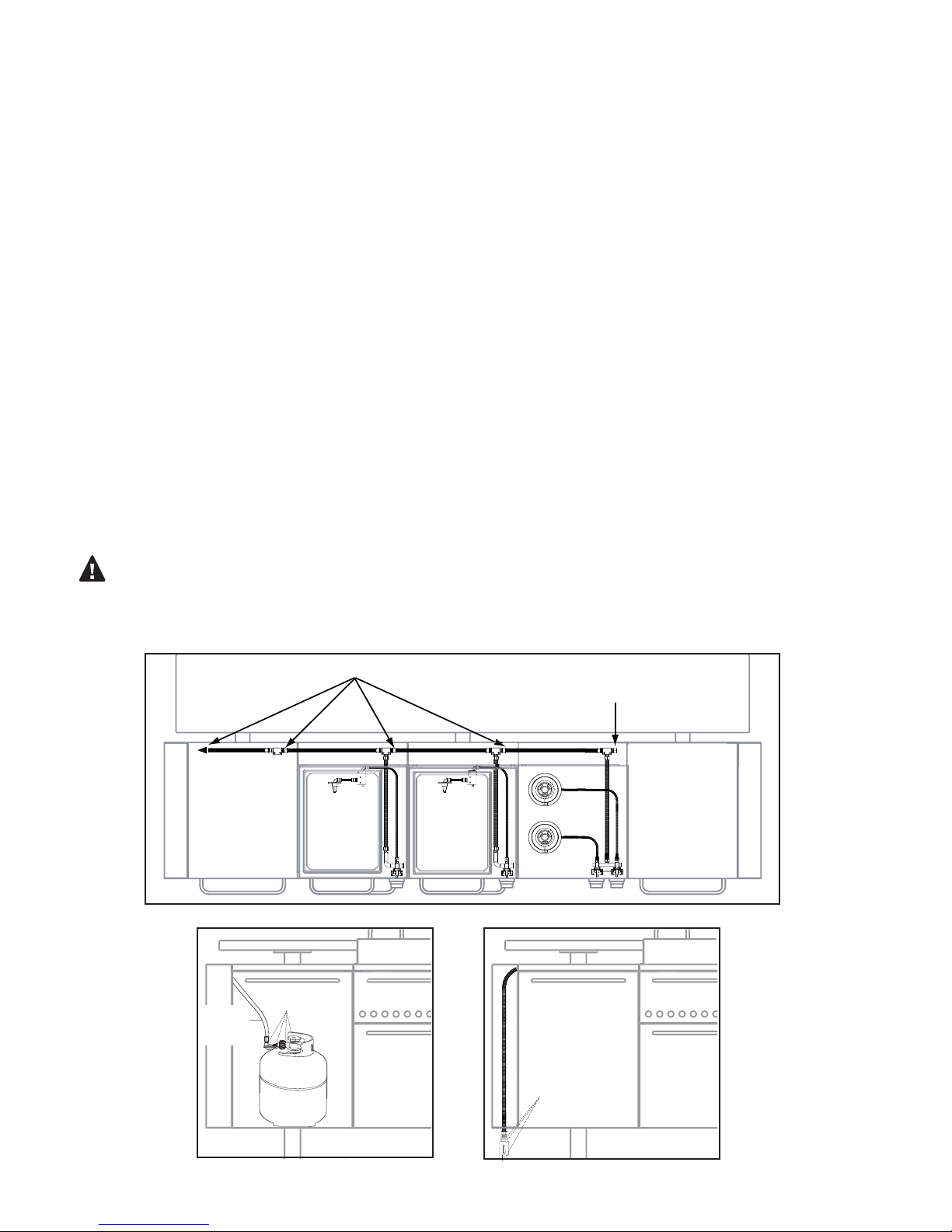
To connect the LP regulator and hose assembly to the tank/
valve assembly, rst make sure the main valve on the tank
is completely closed. Although the ow of gas is stopped
when the Type 1 system is disconnected as part of its safety
feature, you should always turn off the LP tank main valve
(FIG. 02) after each use and during transport of the tank or
unit. Insert the regulator inlet into the tank valve and turn the
black coupler clockwise until the coupler tightens up. Do not
overtighten the coupler. Turn the main tank valve on and turn
the burner control valves on the unit to “HIGH” position for
about 20 seconds to allow the air in the system to purge. Turn
valves off and wait 5 minutes before attempting to light the
burners.
To disconnect the coupler, rst make sure the main tank valve
is turned off. Grasp the coupler and turn counter-clockwise.
The inlet will then disengage. Remove the inlet from the tank
valve opening if it has not already done so when disengaging.
Your local LP lling station should be equipped with the proper
equipment to ll your tank.
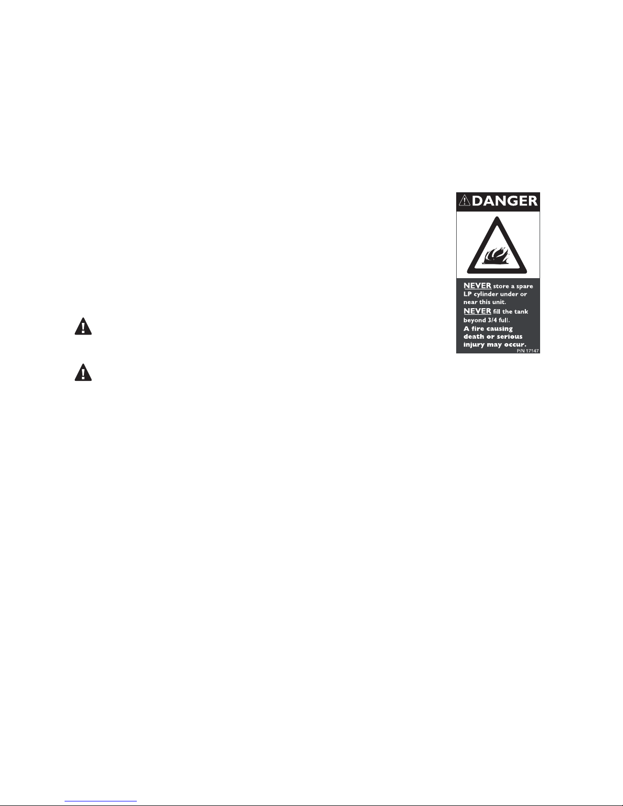
LP TANK REQUIREMENTS:
A dented or rusty LP tank may be hazardous and should be
checked by your LP supplier. Never use a cylinder with a
damaged valve. Always check for leaks after every LP tank
change. The LP gas cylinder must be constructed and marked
in accordance with the specications for LP gas cylinders of
the U.S. Department of Transportation (DOT or CAN/CSA-
B339) and designed for use with a Type 1 system only. Do not
change the regulator and hose assembly from that supplied
with the unit or attempt to use a Type 1 equipped regulator
and hose assembly with a standard 510 POL tank/valve
assembly. The cylinder must be provided with a shutoff valve
terminating in an LP gas supply cylinder valve outlet specied,
as applicable, for connection Type 1. If the appliance is stored
indoors, the cylinder must be disconnected and removed from
the appliance. Cylinders must be stored outdoors in a well-
ventilated area out of the reach of children.
NOTE: When an LP unit is directly attached into an LP house
system, the step down regulator MUST be used to reduce the
supply pressure to a max. 14" W.C. and min. 11" W.C. to the grill
regulator.
Fig. 01 LP Gas
TYPE 1
LP TANK
FA20ALP
LP HOSE
WITH
REGULATOR
Installation must conform with local
codes or with the National Fuel Gas
Code ANSI Z223.1 or the CAN/CGA-
B149.2 Propane Installation Code
Fig. 02 Orice Replacement
NOTE: Do not use LP orices with natural
gas or NG orices with an LP gas tank.

8
GAS REQUIREMENTS: LEAK TESTING
GENERAL:
Although all gas connections on the grill are leak tested at the factory prior to shipment, a complete gas
tightness check must be performed at the installation site due to possible mishandling in shipment, or
excessive pressure unknowingly being applied to the unit. Periodically check the whole system for leaks, or
immediately if the smell of gas is detected.
BEFORE TESTING:
Do not smoke while leak testing. Extinguish all open ames. Never leak test with an open ame. Make a soap
solution of one part liquid detergent and one part water. You will need a spray bottle, brush, or rag to apply
the solution to the ttings. For LP units, check with a full cylinder. Remove the control knobs and battery to
disable accidental ignition. Open the drawer containing LP or natural gas hook up, this is where all tests will be
performed.
TO TEST:
Make sure all control valves are in the “OFF” position. Turn the gas supply “ON”. Check all connections from
the supply line, or LP cylinder up to and including the manifold pipe assembly. Apply the soap solution around
the connection, valve, tubing and end of the manifold. Soap bubbles will appear where a leak is present. If a
leak is present, immediately turn off gas supply, tighten any leaking connections, turn gas on, and recheck.
Check all the gas connections at the base of the control valves where they screw into the manifold pipe.
If you cannot stop a gas leak, turn off the gas supply and call your local gas utility or the dealer you purchased
the appliance from. Only those parts recommended by the manufacturer should be used on the grill.
Substitution can void the warranty.
WARNING:
Do not use the grill until all connections have been checked and do not leak.
Check all gas supply ttings for leaks before each use. It is handy to keep a spray bottle of soapy water near
the shutoff valve of the gas supply valve. Spray all the ttings. Bubbles indicate leaks. (FIG. 03 & 04)
Fig. 04a LP Gas Fig. 04b Natural Gas
LP TANK
LEAK TEST
POINTS
CHECK HOSE
FOR SIGNS OF
ABRASIONS,
CRACKS OR
LEAKS
LEAK TEST
POINTS
NG Main
Ł
to gas
main
Leak Test Points
Termination Cap
Fig. 03 Internal Hoses

9
LIST OF INCLUDED MATERIALS
A
B
FM20ASU: STORAGE UNIT
1 - Storage Unit Body
1 - Teak Top
1 - LP Tank Holder
1 - Drawer Separator
1 - Handle
1 - NG Hose
2 - M6x12 screws w/spacer
4 - M6x12 screws
FM20AGU: GRILL UNIT
w/ GAS DRAWER
1 - Grill Unit Body
1 - Gas Drawer
1 - Cast Iron Grate Frame
1 - Cast Iron Grate
1 - Residue Tray
1 - Lid
3 - Handles
1 - Metal Gas Hose
1 - Control Knob
1 - AA Battery
6 - M6x12 Screws
w/spacer
4 - M6x12 Screws
1 - M6x12 Screw w/Nut
FM20AWU: WARM UNIT
1 - Warming Unit Body
1 - Slate Top
4 - Dish Covers
2 - Storage Dishes
4 - Chang Dishes
2 - Water Dishes
2 - Sterno Holders
1 - Sterno Tray Holder
2 - Handles
4 - M6x12 Screws
w/spacer
4 - M6x12 Screws
1 - M6x12 Screw
UTILITY UNIT
FM20AUFS / FM20AUFR
1 - Back Panel
1 - Bottom Panel
2 - Side Panels
1 - Counter-Top Base
25 - 5/32x3/8 Screws
4 - Leveling Feet
FM20AUS (each) 24” Storage
Cabinet w/Door
1 - Handle
2 - M6x12 Screws w/spacer
4 - Leveling Feet
MOUNTING UNIT w/ DINING
ASSEMBLY
FM20AML - 3 Support Frame
Legs
FM20AMB1 - Aluminum Beam 1
(assembly screw holes on top)
FM20AMB2 - Aluminum Beam 2
6 - Leveling Feet
12 - M6x90 Screws
FM20AEP /
FM20BEP END
PANELS
1 - End Panel A
1 - End Panel B
8 - M6x12 Screws
FM20AIU: INFRARED UNIT
w/ INFRARED DRAWER
1 - Grill Unit Body
1 - Infrared Drawer
1 - Cast Iron Grate Frame
1 - Cast Iron Grate
1 - Residue Tray
1 - Lid
3 - Handles
1 - Metal gas Hose
1 - Control Knob
1 - AA Battery
6 - M6x12 Screws
w/spacer
4 - M6x12 Screws
1 - M6x12 Screw w/Nut
FM20ACU: COOK UNIT
1 - Cook Unit Body
w/ 2 Burners
1 - Cast Iron Grate Frame
2 - Cast Iron Grate
1 - Residue Tray
1 - Lid
2 - Handles
1 - Metal gas Hose
2 - Control Knobs
1 - AA Battery
6 - M6x12 Screws
w/spacer
4 - M6x12 Screws
1 - M6x12 Screw
FM20ALU: LIGHT UNIT
1 - 4 Foot AC Power Cord
3 - Directional 50W GU10
Halogen Light Bulbs
4 - M6x90 Screws

10
DIMENSIONS
Side Front
To p
74 3/4"
25 29/32"
24 1/64"
26 25/32"
21 1/4"
49 13/16"
52 15/32"
42 25/32"
39 49/64"
36"
19 3/32"
27"
29 25/32"
99 23/32"
103 25/32"
INSTALLER FINAL CHECKLIST:
Specied 12 clearances maintained to
combustibles.
Veried proper enclosure ventilation.
Drawers fully close.
All internal packaging removed.
Knobs turn freely.
Each burner lights satisfactorily.
Total weight of unit without counter-tops:
approximately 1200 lbs.
Residue pan in place properly and sliding
freely.
Pressure regulator connected and set for
4.0 W.C. Natural, 11.2 W.C. LP gas.
Manual shutoff valve installed and
accessible.
Unit tested and free of leaks.
User informed of gas supply shutoff valve
location.
All grates are assembled and put in place.

11
ASSEMBLY: FRAME, HANDLES AND KNOBS
(12) Screws Leveling Feet
Beam 1
Beam 2
angled
corner
1. Assemble horizontal support beams to
each support frame leg using (12) type
M6x90 screws as shown in Fig. 05. Note
the position of the angled corner on
Beam 2. Assemble (6) leveling feet to
bottom of the support frame legs. Adjust
height of each leveling foot by turning
clockwise. Make sure frame is level before
proceeding.
2. Remove all packing materials from each
of the modular units. It is recommended
you remove the cooking drawers from
each unit prior to installing them onto the
mounting frame. This will give you easy
access to the screw holes and all internal
connections. See Page 16, Fig. 16 for more
information on removing the cooking
drawers.
Fig. 05
Fig. 06B
Top view
Side view
W ARNING: H OT !
Handle lid with car e. Use grill mitts when using or r em ov ing lid .
Slanted Side of Lid
Fig. 06A
3. Assemble handles to each lid and modular unit drawer using screws provided, Fig. 06A and
B. Handles and screws are included in each modular unit box. Secure control knobs to each
grill/cook unit by placing the knob over the valve stem, Fig. 06B

12
ASSEMBLY: MODULAR UNITS
Installation Screw Holes
Hinged Back Panel
Installation Screw Holes
5
4
1
2
3
optional screw holes
4. Beginning in the center of the
mounting frame, secure the rst grill
unit to the horizontal support beams
by using (2) type M6x12 screws. Fig.
07 Lift up the hinged back panel on
the grill unit to gain access to the top
installaion holes. Pull out the bottom
storage drawer to access the back
installation holes, and use 2 M6x12
screws to attach.
5. Continue installing each modular
unit to the support beams per the
above instructions making sure to
follow the order shown in Fig.08. If
there are gaps between each unit you
can secure them to each other by using
(1) optional type M6x12 screw with nut,
Fig. 08.
Fig. 07
Fig. 08

13
Light Shroud
Screw
Holes
Panel A
Installation
Screws
6. Secure light unit to right side of
modular by using (2) M6x90 type
screws. Fig. 09 Plug power cable
into a 110v outlet. Power cable
can be run through the horizontal
support beam to hide it from view.
Operate lights by using the rocker
switch located on the bottom of
the light shroud. Replace halogen
bulbs with type 50W GU10.
7. Secure left and right end panels
to modular by using (4) type
M6x12 screws per panel. Panels are
labeled A (no light) and B (w/light),
Fig. 10. You will need to remove the
Storage and Warming drawers to
gain access to the installation screw
holes from inside the modular units.
Fig. 09
Fig. 10
ASSEMBLY: LIGHT UNIT AND END PANELS

14
8. Connect the (3) metal gas hoses located in the back of each modular Cook/Grill Unit to the
gas coupler on the opposite end, Fig.11. The right side of each hose is pre-connected at the
factory. Tighten each tting with a wrench to ensure a tight seal.
Fig. 11
ASSEMBLY: GAS CONNECTIONS
coupler
Natural Gas Installation (standard)
9a. Using the provided 1/2” exible gas
hose, connect one end to the rst gas
coupler located inside the left side Storage
Unit, Fig. 12-A. Run opposite end of hose
through left side end panel and connect to
the main natural gas line with shutoff valve,
Fig.12-B.
Grill burner orice size: 1.89mm
Cook burner orice size: 1.50mm
A
B
Fig. 12

15
A
B
Fig. 13
ASSEMBLY: GAS CONNECTIONS
LP Gas Installation (optional, not included)
9b. Purchase LP conversion kit FA20ALP. Using
the provided LP gas hose, connect end without
regulator to the rst gas coupler located
inside the left side storage unit, Fig.13-A. Run
opposite end to LP tank and secure it to the gas
outlet. You must also replace the brass orices
located in each cooking unit. See page 7 for
more LP gas installation information.
Grill burner orice size: 1.30mm
Cook burner orice size: 1.05mm
Note: By default the gas entry point (for
NG and LP) will begin on the left side of the
modular inside the Storage Unit. If you want
the NG entry point to begin on the right side
you will need to relocate the gas termination
cap. The gas termination cap is located in
the cook unit on the right side of the coupler,
Fig. 14. Relocate the gas termination cap to
the left most coupler of the modular unit. The
gas termination cap MUST be in place before
operating.
termination cap
Fig. 14

16
ASSEMBLY: DRAWER INSTALLATION AND GRATE ASSEMBLY
AB
10. Install cooking drawers by
sliding them into into each unit, Fig.
15-A. Lock each drawer in place by
turning the lock at the back of the
drawer counter-clockwise, Fig. 15-B
and Fig. 16
Note: Turn to page 19 if using
optional charcoal drawer instead of
gas or infrared drawers.
Fig. 15
CAUTION: HOT
Do Not Remove Until Cool
OPEN
LOCK
Fig. 16
Fig. 17
11. Remove cast iron frames and
grates from the packing materials
and install over grill and cook units
as shown in Fig. 17.

17
ASSEMBLY: BATTERY INSTALLATION
Fig. 18
12. Open bottom drawer of each grill and
cook unit and locate the ignitor battery
compartment on the right. Install (1) AA
battery per compartment, Fig. 18.
Screw postive battery end into coil. Ensure firm
contact is made before inserting into battery box.
Warning: Lid may get extremely hot while cooking, always
use a grill mitt for hand and arm protection.
Use smaller end of handle to tilt lid in order
to view food while cooking.
When lifting lid, grasp handle in the center
for stability.

18
ASSEMBLY: WARMING DRAWER
Chafing Dishes
Water Pans
Water Pan Frame
Sterno Holders
Sterno Holder
Tray
Fig. 19
Remove protective lm from all
warming drawer components.
Assemble bottom of warming
drawer per Fig. 19.
Using the Warming Drawer
1. Fill water pan with about 3/4” to 1-1/2” of hot water.
2. Add food to the chang dishes.
3. Slide out Sterno holder tray and add Sterno fuel into the holders. Light with a match. Check
the Sterno to see approximately how long it will burn for. Slide the Sterno holder tray back in.
WARNING:
Chang dishes are not used to cook food, they are intended only to keep food warm.
Do not leave an open ame unattended.
Do not use anything but sterno type fuel in warming drawer.
Do not put unit a hot stove or open ame.
Never use chafers without water in the water pans.
Open lids carefully so that rising steam does not burn you face or hands.
Maintaining Chafer Dishes While in Use:
Occasionally stir the food to make sure the bottom doesn’t burn.
If you need to add more Sterno, the old burners may be hot so use tongs to remove them.
The above is intended to be used as a guide. For any questions please do not hesitate to
contact us.
The warming drawer consists of a top drawer with two dishes that can be used to store ice or
other condiments and a bottom drawer with two chang dishes to keep your food warm.

19
Optional Charcoal Drawer Model: FA20ACD
Sold separately
CAUTION: Charcoal drawer should be inserted
into position opposite the propane tank. If
using two charcoal drawers, make sure to
remove propane tank and properly store it
before cooking with charcoal.
CAUTION: Follow instructions located on back
of charcoal bag before cooking.
CAUTION: When using lighter uid, follow
instructions on container prior to use.
ASSEMBLY INSTRUCTIONS:
1. Assemble charcoal drawer kit by
following the diagram in Fig.20.
2. Follow reverse instructions on page 17
to remove cast iron grates and remove
cooking drawer.
Note: Mesquite chip holder is optional
and only necessary if using mesquite
chips for added avor.
3. Slide drawer into unit.
4. Add charcoal to top of charcoal tray
and light.
5. Begin cooking.
REMOVAL INSTRUCTIONS:
1. Never remove charcoal drawer while
drawer is hot.
2. Properly dispose of charcoal remains
once charcoal briquettes have been
incinerated.
3. Return emptied charcoal drawer to grill.
WARNING:
Keep the area surrounding the grill free from
combustibles, trash or combustible uids and
vapors such as gasolines or charcoal lighter
uid. Do not obstruct the ow of combustion
or ventilation air.
WARNING:
Never leave grill unattended and keep out of
reach of children.
WARNING:
Use caution when using lighter uid to ignite
charcoal, follow manufacturers instructions on
the back of the lighter uid container.
MESQUITE
CHIP HOLDER
CHARCOAL
TRAY
CHARCOAL
BASKET
CHARCOAL
DRAWER
FIG. 20
ASSEMBLED DRAWER
NOTE:CHIP
HOLDER
RESTS UNDER
CHARCOAL
BASKET HANDLES
ASSEMBLY: OPTIONAL CHARCOAL DRAWER

20
ASSEMBLY: UTILITY UNIT
13. The Utility Unit Housing is shipped in three
boxes and must be assembled, Fig. 21. Begin
by attaching bottom panel A to the back panel
using (2) type 5/32x 3/8" screws. Assemble
leveling feet to each side panel. Secure the
two side panels (B) to the back panel using
(4) type 5/32”x 3/8” screws for each panel.
Finalize the Utility Unit Housing by placing
the counter-top base on top of the assembled
frame and secure using (4) type 5/32”x 3/8”
screws.
A gang box cut-out is built in to
accomodate AC power entry. Purchase an
outdoor gang box from your local hardware
store, Fig. 22.
15. Assemble all handles and leveling feet to
the 24” storage units. Slide each storage unit
into Utility Unit Housing to t in place, Fig. 23.
16. Should you choose not to use the storage
units, the Utility Unit has space to accomodate
(2) 24” refrigerators or (1) 48” refrigerator.
The refrigerators can be plugged into the
gang box. An overlay kit is also available
to t over select refrigerators, see optional
accessories on page 31 for more information.
Gang Box
Opening
Fig. 22
A
B
B
C
Fig. 21
Fig. 23
This manual suits for next models
5
Table of contents
Other Fuego Grill manuals

Fuego
Fuego FELG21C User manual

Fuego
Fuego F36S-Pro User manual

Fuego
Fuego EP01AMG User manual

Fuego
Fuego Element F21C-H User manual

Fuego
Fuego F36S-Pro-NG User manual

Fuego
Fuego F21C User manual

Fuego
Fuego F-Series User manual

Fuego
Fuego F27S-Griddle User manual

Fuego
Fuego FENG21S User manual

Fuego
Fuego F36S-Pro-B User manual