147220126, No Rev Sheet 8 of 14
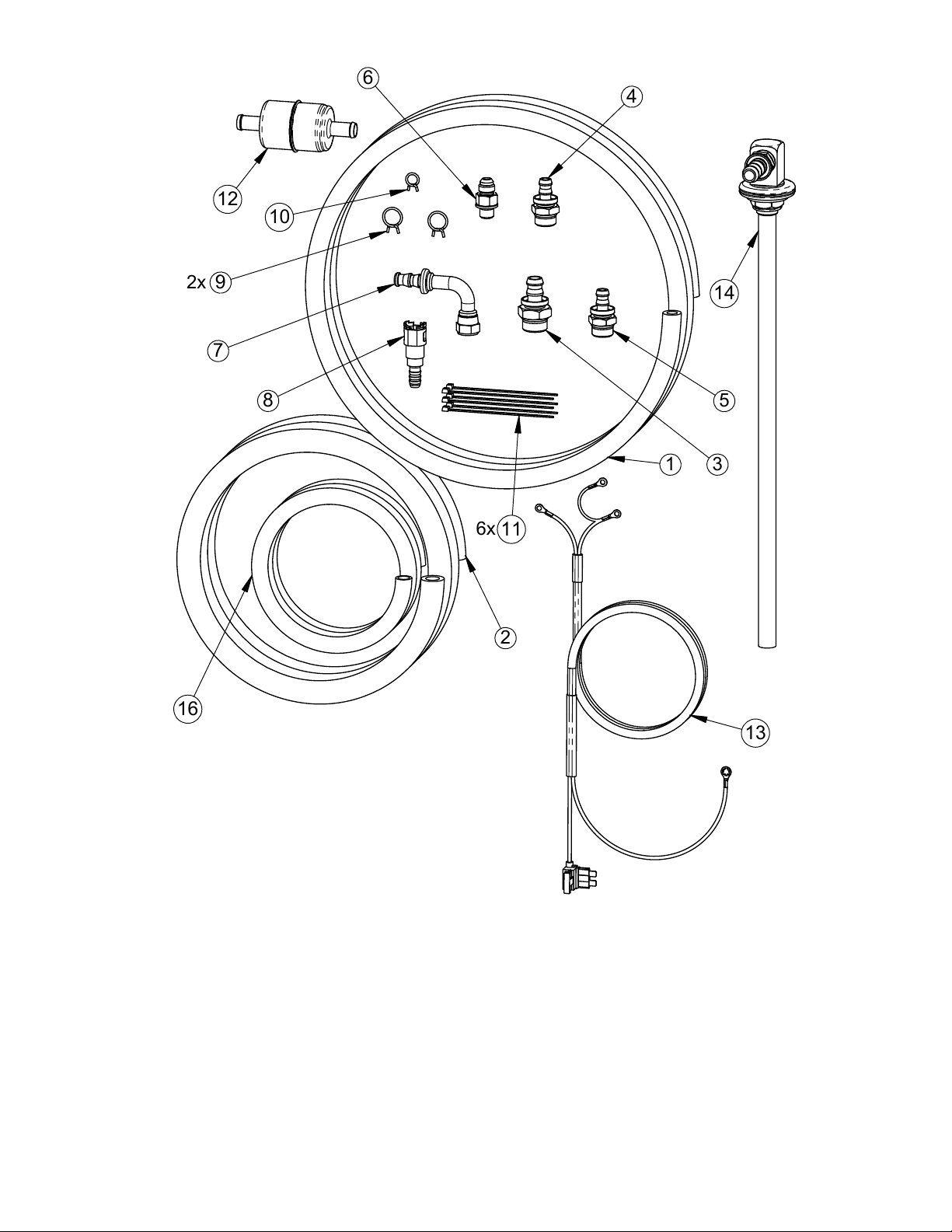
Due to variations of depth between various fuel tanks, the draw tube included in this kit (item 14) will have to be cut
to the correct length. If too much length is cut from the draw tube, then the vehicle will prematurely “run out of fuel”
while significant fuel still remains in tank. If the draw tube is too long, then the tube can be crushed upon
installation of the fuel tank.
To derive the correct length to cut from the end of the Draw Tube Kit (item 14), loosen and remove the locking nut
and washer from the Draw Tube Kit (item 14). The remaining rubber grommet and rubber washer should remain
on the Draw Tube Kit. Insert the draw tube into the fuel tank module, until it hits the bottom of the fuel tank module.
SPECIAL NOTE: Some fuel tank modules are spring loaded when inserted in the tank. Fuel tank modules such
as these that can change length, when inserted in the tank. Fuel tank modules in this configuration must
first be dry-fitted into the fuel tank prior to continuing, to ensure that the proper length of the draw tube is
determined. In cases such as this, it is important to remove the fuel from the tank, and support the fuel
tank along the outside of tank (or along straps) during this measurement procedure. This is done so that
the tank’s center is not pushed up during measurement (for higher accuracy).
Once the tube hits the bottom of the fuel tank module, a gap will form between the top of the fuel tank module and
the bottom of the rubber grommet of the Draw Tube Kit. Measure this gap and write it down. Add 1/4” to 3/8” to
this earlier measurement. Cut this calculated length of tube from the plastic tube portion of the Draw Tube Kit (item
14). This cut should be performed at an angle, to prevent the bottom of the fuel tank module from closing off fuel
flow, should the measurement be off, or fuel tank is later dented or tank shape is changed after tank installation.
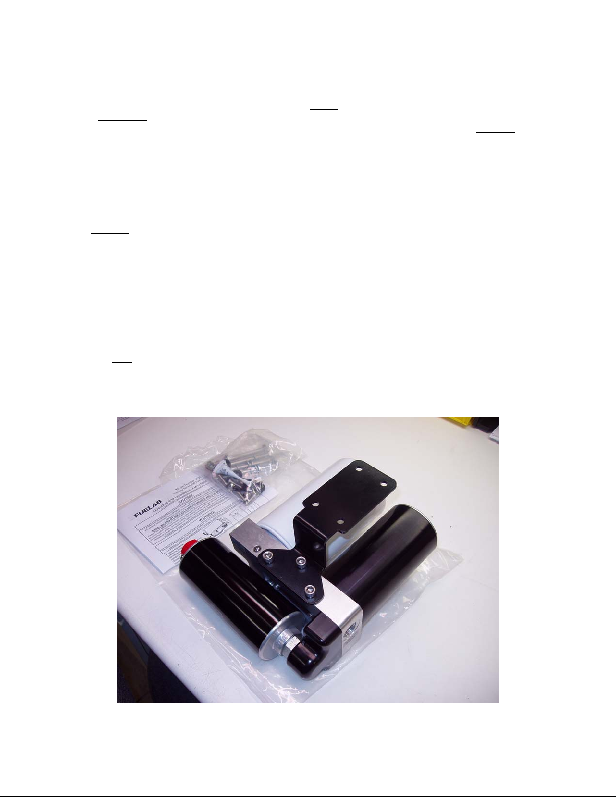
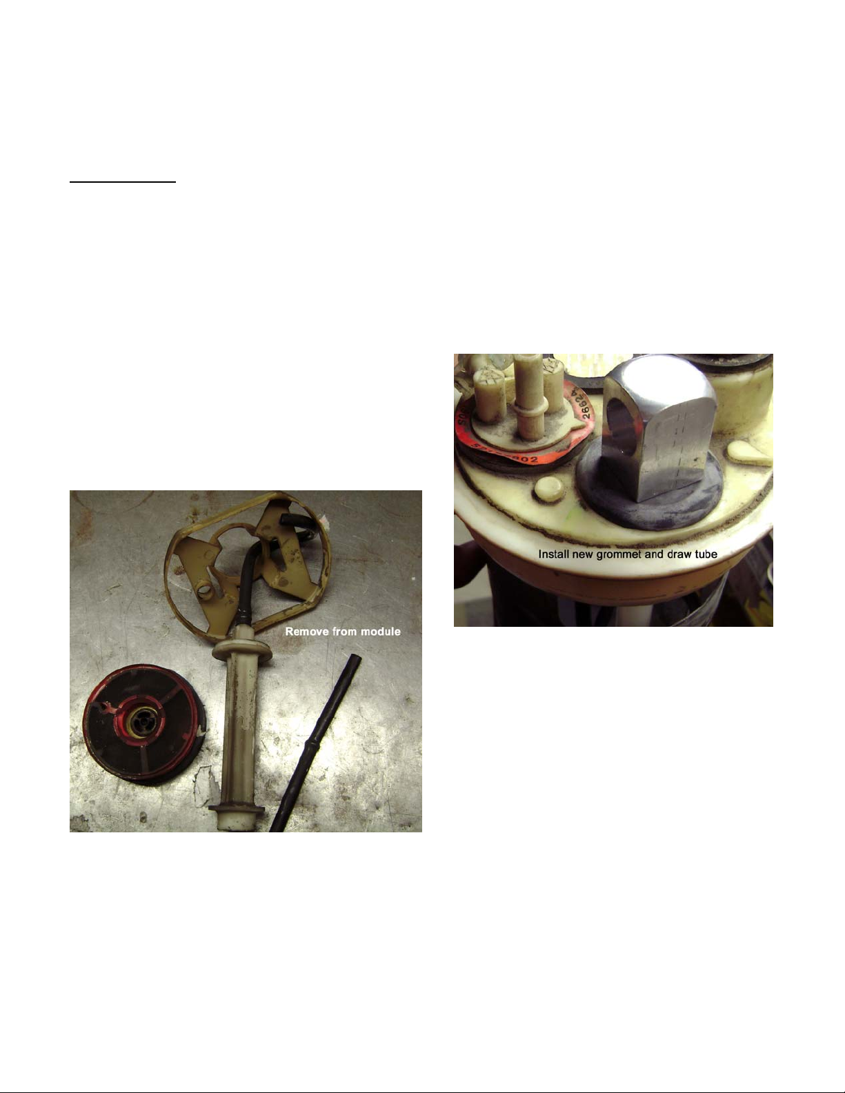
Remove fuel tank module from tank (if applicable) and
reinstall the modified Draw Tube Kit (item 14) back into the
fuel tank module. Re-install the kit washer and locking nut
back onto the threads of the Draw Tube Kit. Orientate the
outlet of the draw tube kit to point toward the same direction
as the original path of fuel lines. Tighten the nut until the
rubber grommet slightly compresses. See photo to right as
example (note: draw tube fitting is not pictured).
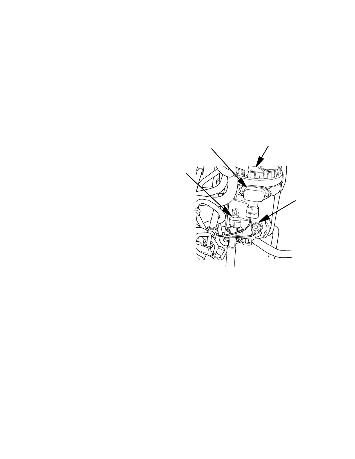
Remove and discard the original in-tank fuel pump from
the fuel tank module (if present), and wire tie any wiring
from pump, to secure (wiring of fuel pump is no longer
required, do not short wires together). Wiring is still
required for the fuel tank level sender. Remove other
unneeded components within the fuel tank module as
well including additional straining filters (such as shown
in the photo to the left).
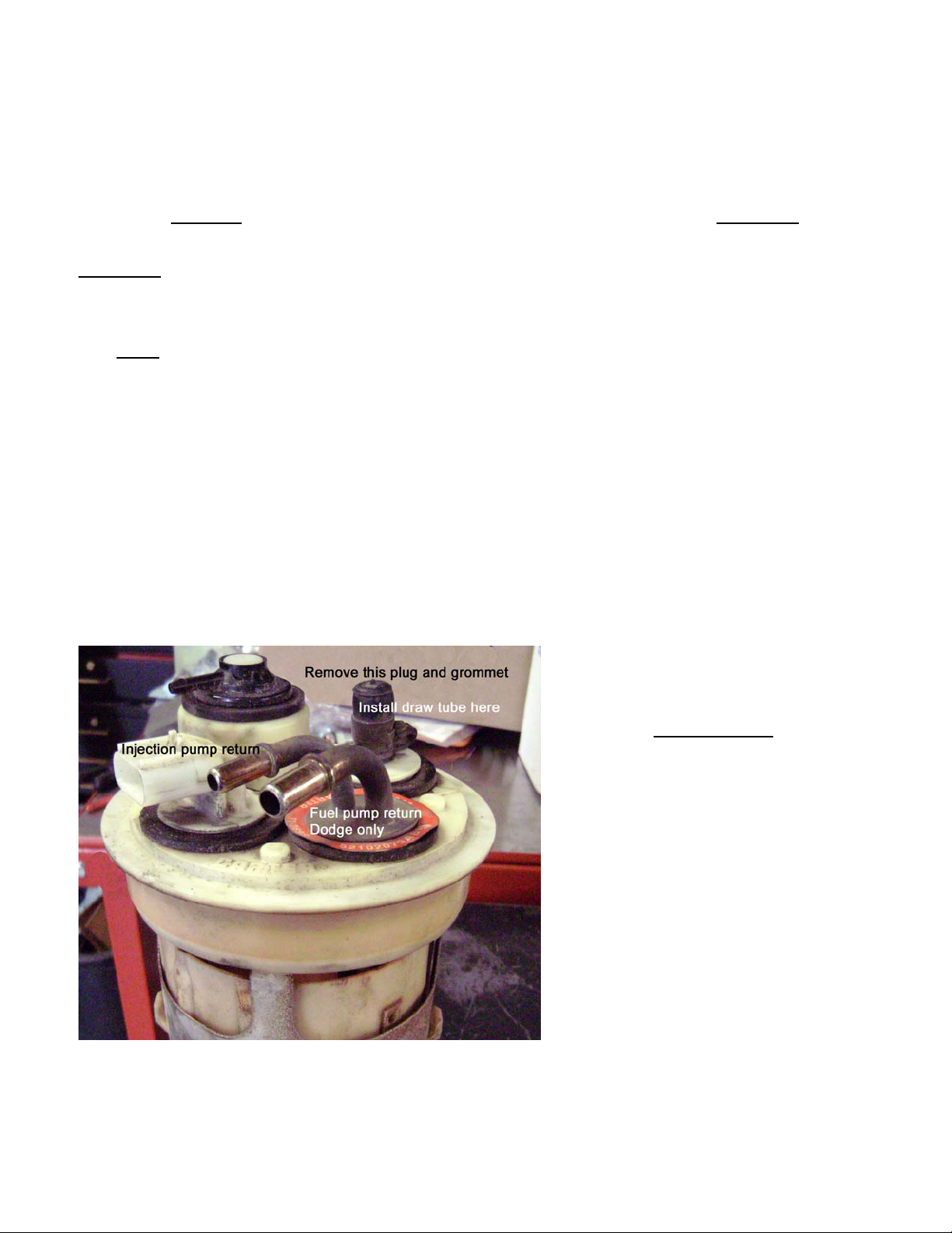
The fuel tank module’s original supply line (from in-tank
pump) is now to be used as the overfill (return) line for
the new Lift Pump / Filtration System. Returning fuel
from the Lift Pump / Filtration System should be
returned below the fuel surface level. This prevents aeration of the fuel that can lead to excessive entrained air
within the fuel that can cause a loss of, or inconsistent fuel pressure.
Use a small section of fuel compatible hose and attach to the bottom of return tube if required. Replacement quick
connect, for the new return line, is included with this Kit (item 8) to attach to the fuel tank module, during fuel tank
re-installation.
Drill a 1/2” hole in the side of the fuel tank module (as shown in picture). Drill an additional two holes approximately
3/4” in diameter at the bottom of the fuel tank module as shown as well. This step allows adequate fuel flow to
enter the fuel tank module. Deburr all holes drilled and use compressed air to blow out remaining plastic chips
(machining burrs) and loose debris. Take time to double check and clean or wipe the surface of the fuel tank
module that mate against the fuel tank / module seal.