Fuelab 72001 User manual

Fuel Pump Controller
120020125-1, No Rev. Page 1 of 4
Model Number 72001
External DC Brushless Fuel Pump Controller
Operating and Installation Instructions
C
CA
AU
UT
TI
IO
ON
N!
!
This product is to be installed only by persons knowledgeable in the repair and modification of vehicle fuel systems
and general vehicle systems modification. Only a qualified technician or mechanic who is aware of applicable
safety procedures and fabrication skills should perform the installation of this product.
GASOLINE AND OTHER FUELS ARE FLAMMABLE AND CAN BE EXPLOSIVE!
Perform the installation in a well ventilated location only to minimize the build up of fuel vapors. NO open flames,
smoking or other sources of ignition are to be present during installation, to prevent fire or explosion that can cause
serious injury or death. Grinding, cutting, and drilling must be performed with care to prevent ignition. Draining and
removal of all fuel and ventilation of vapors in vehicle and fuel system is recommended when performing such
procedures. Proper eye and personal protection is required at all times during installation.
W
WA
AR
RN
NI
IN
NG
G!
!
The Vehicle’s fuel system may be under pressure! Do not loosen any fuel connections until relieving all fuel system
pressure. Consult an applicable service manual for instructions to relieve fuel system pressure safely.
This product is intended for racing, off-road, or marine use only. This fuel system component may not be legal for
sale or use on emission controlled motor vehicles; consult local, state and national laws.
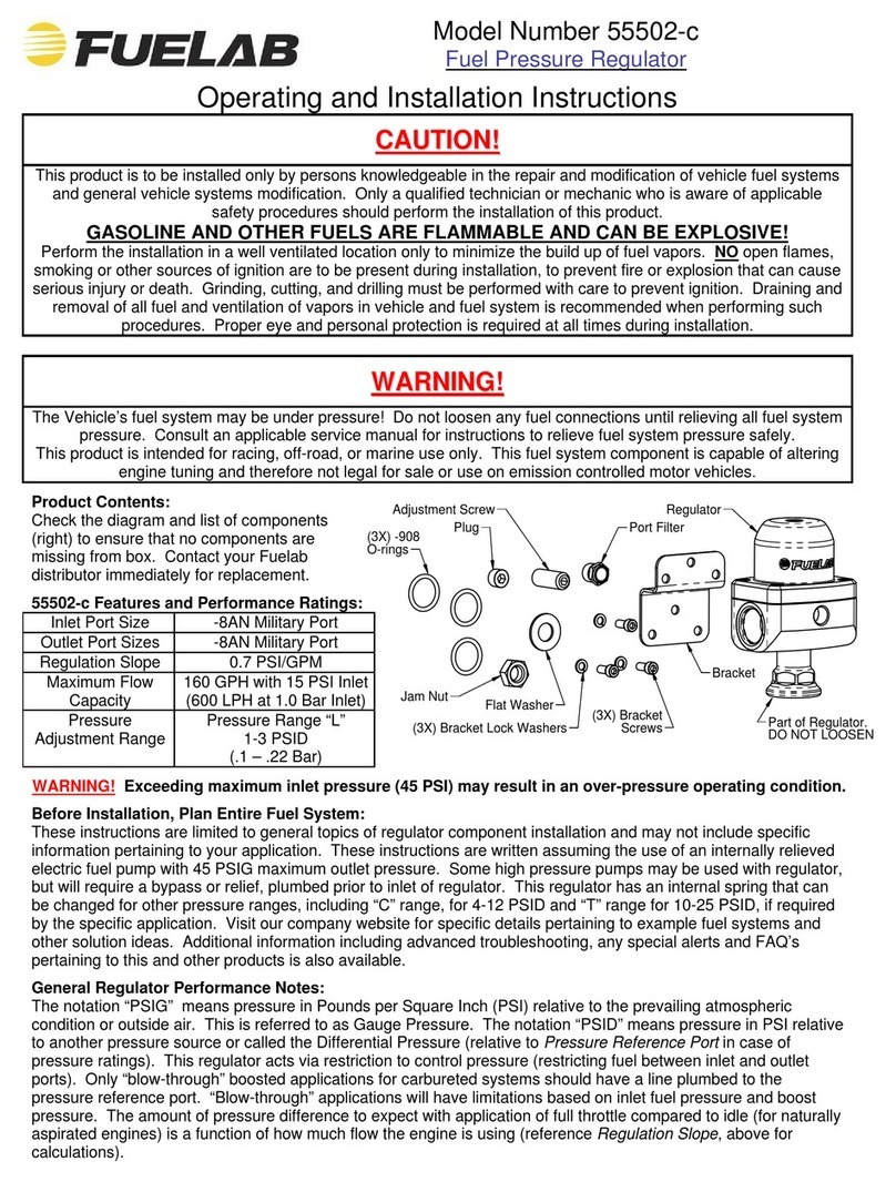
Product Contents:
Check the diagram and list of components (right)
to ensure that no components are missing from
box. Contact your Fuelab distributor immediately
for replacement.
72001 Features and Performance Ratings:
Pump Compatibility 3 Phase DC Brushless
Fuel Pumps ONLY!
(without an internal
electronic controller)
Maximum Current
Draw
20 Amperes
Operating Voltage 8-18 Volts
WARNING!
This DC Brushless Fuel Pump Controller is ONLY compatible with 3 Phase DC Brushless Fuel
Pumps without an internal electronic controller. 3 Phase Brushless Fuel Pumps feature three wires that
are directly attached to the internal motor's stator windings. This controller is INCOMPATIBLE with
ANY two-wire systems.
Before Installation, Plan Entire Fuel System:
A complete design plan of the entire fuel system must be created for the specific application. These instructions are
a guide to help design this plan with respects to integrating this model of external fuel pump controller only. Consult
other sources of information and manufacturers instructions for the various components of the fuel system. These
instructions are limited to general topics of Fuel Pump Controller installation and may not include specific
information pertaining to your specific application. Visit our company website (www.fuelab.com) for specific details
pertaining to example fuel systems and other solution ideas. Additional information including advanced
troubleshooting, any special alerts and FAQ’s pertaining to this and other products is also available. A good design
plan for the fuel system must contain consideration for: Pressure and flow rate through various components, quality
of components, operating environment (temperature, vibration, shock, general exposure to elements) and local area
laws. Begin installation of External DC Brushless Fuel Pump Controller only after a complete plan is established to
help avoid fuel system component failure, costly rework, and excessive installation time.

Fuelab Model
72001 Fuel Pump
Controller
DC Brushless
Fuel Pump
120020125-1, No Rev. Page 2 of 4
CIRCUIT
BREAKER
or FUSE C
NO
NC
FUEL PUMP
POWER RELAY
VEHICLE BATTERY
VEHICLE ELECTRICAL SYSTEM
IGNITION
SWITCH
or ECM
(16-20ga)
(30+A RATING)
(20A)
(12-18 VOLT SYSTEM)
FUSED
CIRCUIT
(1-5A)
(12-14ga)
(12-
14ga)
(12-14ga)
RED / BLK / YEL
MOTOR PHASE
(14-16ga)
BLK
RED
Electrical Planning Notes:
Reference below, for schematic wiring diagram example. Use electrical components as described including
electrical connectors that are appropriate for the operating environment of the fuel system, whether its use in street,
racing, or marine applications. Electrical connectors for the power leads must be capable of high current draw,
note all connections, wire and component rating requirements herein. Solder and use shrink wrap for wire splices
for extra reliability. Main wiring schematic diagram below shows the control of relay by ignition switch. This source
can be changed as described, or by a toggle switch. Some forms of racing have specific rules regarding electrical
switching of fuel system. Consult appropriate racing guidelines, rules and regulations.
MAIN WIRING SCHEMATIC DIAGRAM: (Electrical components shown are not supplied with controller)
Installation Steps:
1. Disconnect the ground terminal from battery and allow the vehicle’s engine and exhaust system to cool.
Relieve fuel system pressure per applicable service manual. Follow all Warnings, Cautions and Instructions
written on previous pages of these instructions.
2. Modify, remove or replace other fuel system components as required per established build plan (reference
notes on previous pages and above).
3. Use the base of the Controller as a drilling template to mark holes for mounting. Choose a location that
minimizes exposure to road hazards and debris, away from engine exhaust pipes, near Fuel Pump (to minimize
length of motor phase wiring). Use high quality mounting hardware (not supplied) to mount Controller to the
vehicle securely. SPECIAL NOTE: DO NOT mount Controller within fuel cell or fuel tank! Use only sealed
bulkhead connectors to feed wiring for in-tank applications such as use of Fuelab Model 74101 Feedthru.
4. Inspect fuel system for any contact of fuel lines or wires with other components that can cause chafing or
rubbing. Secure all components and fuel lines. Ensure that moving components of vehicle are clear. Minimize
the distance between the Fuel Pump Controller and the Fuel Pump. Excessive lengths of motor phase wiring
can lead to permanent Controller Damage. SPECIAL NOTE: Final connections for fuel pump wiring (three
motor phase wires) may require verification for proper direction to ensure correct direction of fuel flow. If fuel
pump is operating in the reverse direction, swap two of the three phase (Pump) wiring with each other (any two
of the three wires). This action reverses the motor and pumping direction. DO NOT reverse incoming power
polarity (exchanging the Red "+" wire with the Black "–" wire). Reverse polarity for the incoming electrical
power to the controller WILL result in permanent damage, preventing operation.
5. Connect the vehicle’s battery. Perform initial priming (and verification of correct pumping direction): This action
can be accomplished by removing fuel line from fuel rail (downstream of fuel pump and filter), allowing the fuel
line to empty fluid into fuel safe container. Operate fuel system until fuel exits fuel line. If fuel does not exit fuel
line or if a partial vacuum is experienced at the end of the fuel line, then consult Note 3 herein to reverse the
motor phase wiring to correct pumping direction. Repeat priming operation as required. Attach fuel line back to
the fuel rail after priming fuel system. After tightening connection, verify leak-free operation while checking fuel
rail pressure. If fuel pressure is not high enough, repeat priming procedure to ensure that fuel system is
properly purged of air. Turn on fuel system (typically by bypassing fuel pump relay) without engine operating.
ECU or engine management computer may be controlling the relay. The ECU may only operate fuel system for

120020125-1, No Rev. Page 3 of 4
a few seconds each time ignition switch is set to on. The fuel system will have to operate several seconds
(30+) to prime and drive air out of the fuel system. Inspect vehicle for any leaks. Turn off fuel system and
repair any leaks that may be present before continuing.
6. Follow other component installation instructions or other applicable service manuals to perform all applicable
inspections and determinations for an adequately operating fuel system.
Fuel System Maintenance Notes:
Periodic inspection and general maintenance is required for longevity and reliability of the fuel system. This action
directly affects the fuel pump's performance and reliability. Included with that are periodic inspection and/or filter
element replacement. Straining Filters (upstream of Fuel Pump as well as internal straining filters) should be
checked and cleaned at least every 50,000 miles (more often for off-road operating conditions). Replace or clean
downstream filters (after Fuel Pump) every year or 15,000 miles (more often for off-road operating conditions).
Dirty fuel filters can block flow and adversely affect fuel system performance as well as can directly damage the
Fuel Pump and Fuel Pump Controller.
Special alert for E85 or Methanol Users: DO NOT use cellulose (paper) based filter elements! Water can
contaminate the fuel and break down the element, creating debris that can damage injectors and Fuel Pump.
Troubleshooting Notes:
Problem (Symptom) Possible Causes Possible Solutions
Not operating. x Faulty fuel pump relay.
x Faulty, dirty or corroded
electrical connections or
improperly sized wire.
x Faulty, dirty or corroded
electrical connections or
improperly sized wiring
between Controller and
Fuel Pump.
Check voltage to Fuel Surge Tank, at power
terminals. If voltage is steady and consistent
(within 1/2 Volt of battery) then contact Fuelab
for assistance or repair. If voltage is
inconsistent as described, repair or replace
electrical components as required.
Not building up fuel
pressure.
x Incorrect fuel system initial
priming procedure.
x Improperly mounted Fuel
Pump or low fuel level.
x Fuel Pump may be
operating in reverse
direction.
Repeat procedure for proper priming, check fuel
level as well as Controller voltage. Consult
Installation Step 5, herein. If verified that pump
operation may be reversed, consult "Fuel Pump
operating in reverse flow" on next line of these
Troubleshooting Notes.
Fuel Pump operating in
reverse flow.
x Incorrect order for 3 phase
pump / motor wiring.
Switch two of the three pump / motor output
wires with each other. Consult Installation Step
4, herein and recheck fuel flow per Installation
Step 5, herein.
Please do not return this product to your retailer. If you experience any performance, reliability
or problems during installation or use of this product, please contact Fuelab immediately!
For more tips, advise or troubleshooting please visit our website at www.fuelab.com, e-mail
message to [email protected] or call our tech department at 618-344-3300 between 8am and
5pm Central Standard Time.

120020125-1, No Rev Sheet 4 of 4
LIMITED WARRANTY
FUELAB, a division of FCP, Inc. , having its principal place of business at 1605 Eastport Plaza Drive, Suite 125,
Collinsville, IL 62234, USA ("Manufacturer") warrants its FUELAB products (the "Products") as follows:
1. Limited Warranty.
Manufacturer warrants that the Products sold hereunder will be free from defects in material and workmanship for a
period of 2 Years from the date of purchase to the original purchaser. If the Products do not conform to this Limited
Warranty during the warranty period (as herein above specified), Buyer shall notify Manufacturer in writing, or by
phone, of the claimed defects and demonstrate to Manufacturer satisfaction that said defects are covered by this
Limited Warranty. If the defects are properly reported to Manufacturer within the warranty period, and the defects
are of such type and nature as to be covered by this warranty, Manufacturer shall, at its own expense, furnish
replacement Products or, at Manufacturer's option, replacement parts for the defective Products. Removal of
Products from vehicle (Vehicle means any automotive, bike or marine transportation powered by an internal
combustion engine. This product is NOT intended or designed for use on aircraft, experimental or otherwise.),
shipping to Manufacturer and installation of the replacement Products or replacement parts shall be at Buyer's
expense.
2. Other Limits.
THE FOREGOING IS IN LIEU OF ALL OTHER WARRANTIES, EXPRESS OR IMPLIED, INCLUDING BUT NOT
LIMITED TO THE IMPLIED WARRANTIES OF MERCHANTABILITY AND FITNESS FOR A PARTICULAR
PURPOSE. Manufacturer does not warrant against damages or defects arising out of improper or abnormal use or
handling of the Products; against defects or damages arising from improper installation (where installation is by
persons other than Manufacturer), against defects in products or components not manufactured by Manufacturer,
or against damages resulting from such non-Manufacturer made products or components. Manufacturer passes on
to Buyer the warranty it received (if any) from the maker thereof of such non-Manufacturer made products or
components. This warranty also does not apply to Products upon which repairs have been effected or attempted
by persons other than pursuant to written authorization by Manufacturer.
3. Exclusive Obligation.
THIS WARRANTY IS EXCLUSIVE. The sole and exclusive obligation of Manufacturer shall be to repair or replace
the defective Products in the manner and for the period provided above. Manufacturer shall not have any other
obligation with respect to the Products or any part thereof, whether based on contract, tort, strict liability or
otherwise. Under no circumstances, whether based on this Limited Warranty or otherwise, shall Manufacturer be
liable for incidental, special, or consequential damages.
4. Other Statements.
Manufacturer's employees, representatives' and/or resellers ORAL OR OTHER WRITTEN STATEMENTS DO NOT
CONSTITUTE WARRANTIES, shall not be relied upon by Buyer, and are not a part of the contract for sale or this
limited warranty.
5. Entire Obligation.
This Limited Warranty states the entire obligation of Manufacturer with respect to the Products. If any part of this
Limited Warranty is determined to be void or illegal, the remainder shall remain in full force and effect.
6. Warranty Service
What Does This Warranty Not Cover? Any problem that is caused by abuse, misuse, or an act of God (such as a
flood) is not covered. Also, consequential and incidental damages are not recoverable under this warranty. Some
states do not allow the exclusion or limitation of incidental or consequential damages, so the above limitation or
exclusion may not apply to you.
How Do You Get Service? In order to be eligible for service under this warranty you MUST return the Warranty
Registration card, or register on-line at www.fuelab.com/warranty-registration within 30 days of purchasing the
Product.
If something goes wrong with your product contact FUELAB at 618-344-3300, or send an e-mail to:
[email protected] for a Return Authorization Number (RMA). After receiving your RMA send it postage paid, fully
insured, with a brief written description of the problem to:
FUELAB Warranty Department, 1605 Eastport Plaza Drive, Suite 125, Collinsville, IL 62234
We will inspect your Product and contact you within 72 hours of receipt to give the results of our inspection and an
estimate of the labor and/or parts charges required to fix the Product, if applicable. If covered under this limited
warranty Manufacturer will repair Product and return it to you at no cost. If the Product is NOT covered under this
warranty and if you authorize repairs, we will return the repaired Product to you COD, or prepaid via credit card,
within 72 hours. There is no charge for inspection. If return product is found to be free of defects a $25.00 shipping
and handling charge will be applied. We will return the repaired Product to you COD, or prepaid via credit card,
within 72 hours.
Other Fuelab Controllers manuals
Popular Controllers manuals by other brands

White Rodgers
White Rodgers 24A06G-1 installation instructions

Morningstar
Morningstar TriStar TS-60M Installation, operation and maintenance manual

ABB
ABB PSTX1250 quick start guide

RIB
RIB BLOCK Wi-Fi ACG6098 instructions

Kohzu Precision
Kohzu Precision MontBlanc KOSMOS Series user manual

RKC INSTRUMENT
RKC INSTRUMENT CB100 Series instruction manual