3
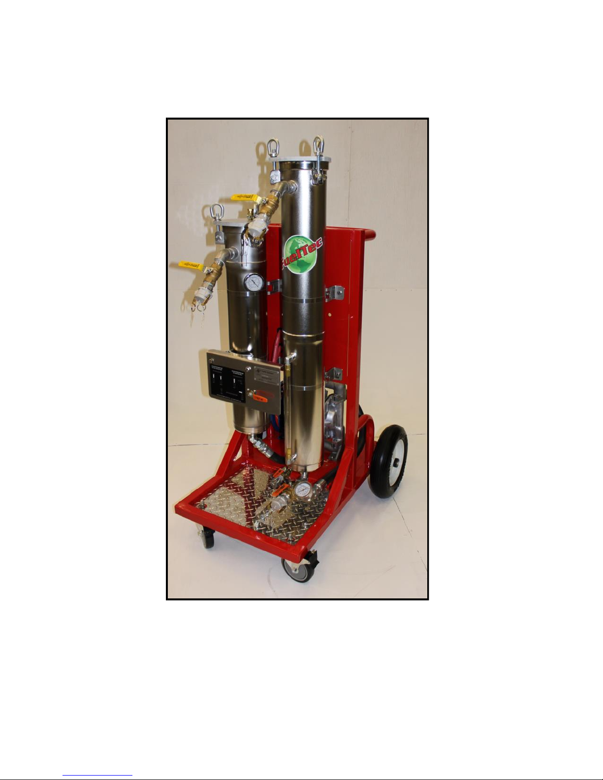
2014 Fueltec 950AW & 955SS Manual
Item SPECIFICATIONS Model 950AW Model 955SS
1Chassis Steel and Aluminum Brite Tread Standard Standard
2Air Diaphragm Fuel Pump flow rate* 0– 720 GPH 0– 2100 GPH
3Compressed Air Required at 40 PSI 10-16 CFM 20-25 CFM
4Maximum Lift wet 22 feet 22 feet
5Primary Stainless Steel Filter Housing 24 inch bag 24 inch bag
6Fuel Pressure Working Max. 40 PSI 40 PSI
7Separated Water Trap Capacity 2 gallons 2 gallons
8Filter/ Coalescer Micro-glass (Mil Type) CF-10 inch CF-20 inch
9Water Separator Teflon coated Stainless Steel S-11 inch S-22 inch
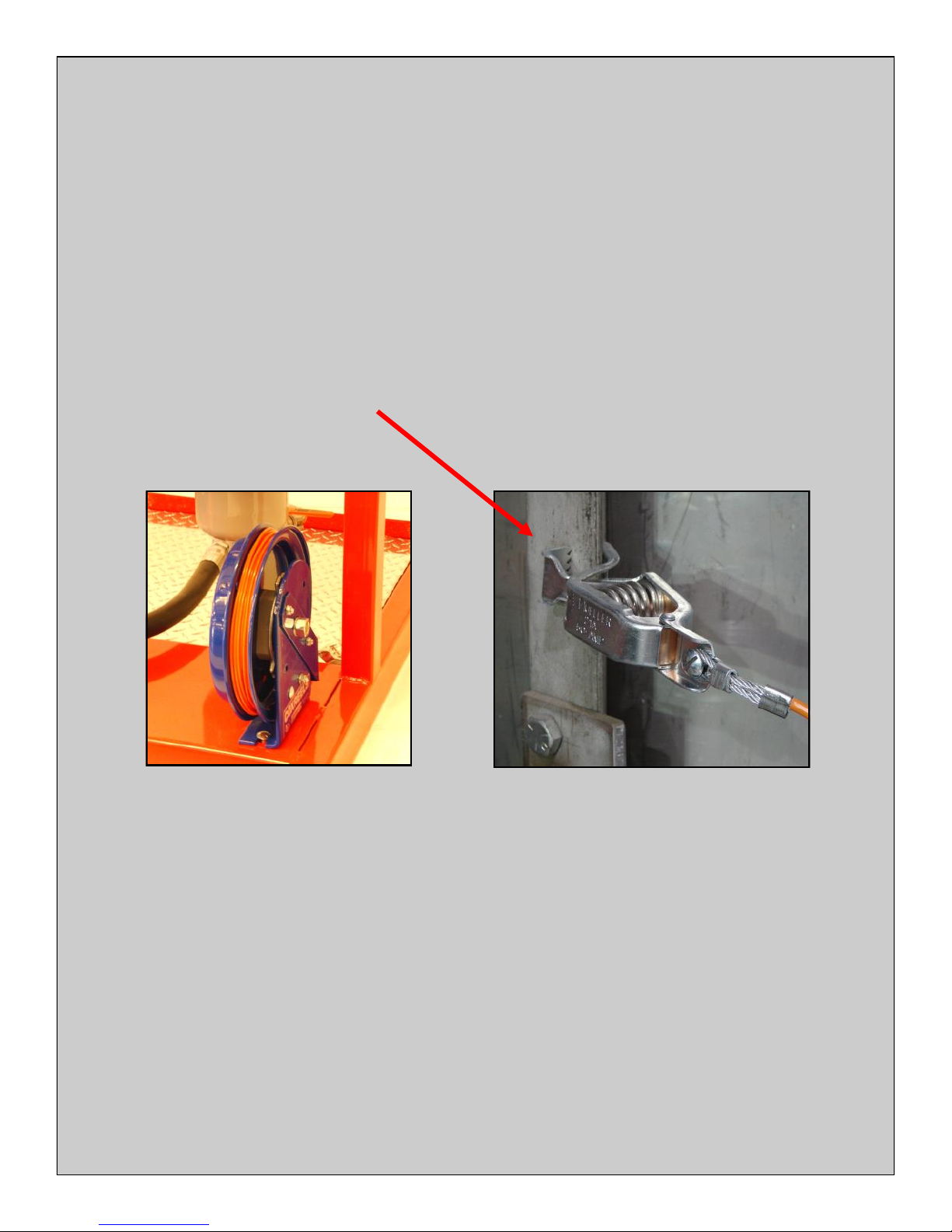
10 Supply & Return Fuel Hose with cam-lock connectors 1 inch X 12 foot 1 inch X 12 foot
11 Separated Water Sight Gauge Standard Standard
12 Swing Bolt Housing Cover for Quick Filter Change Standard Standard
13 Separated Water Drain while System is Running Standard Standard
14 Filter Condition Vacuum Gauge Standard Standard
15 Coalescer Pressure Gauge Standard Standard
16 Air Regulator and Pressure Relief Valve Standard Standard
17 Width X Length X Height.. Lbs. 32x47x60..250lbs. 32x47x61.. 325 lbs.
WARNING: Read carefully and understand all
INSTRUCTIONS before operating. Failure to follow the safety
rules and other basic safety precautions may result in serious
personal injury, or death.
It is important that you read the entire manual to
become familiar with this product before you begin using it.
This machine is designed for certain applications only. FuelTec Systems cannot be
responsible for issues arising from modification. We strongly recommend this machine is not modified and/or used
for any application other than that for which it was designed. If you have any questions relative to a particular appli-
cation, DO NOT use the machine until you have first contacted FuelTec Systems to determine if it can or should be
performed on the product.
* Flow rates may vary with compressed air supply, filter type and condition, length and size of hoses, and
size and shape of fluid pickup and return tubes.
General Safety Regulations
WARNING: Maximum air pressure setting not to exceed forty (40) psi.
WARNING: The warnings, cautions, and instructions discussed in this instruction
manual cannot cover all possible conditions or situations that could occur. It must be
understood by the operator that common sense and caution are factors which cannot be built into this product,
but must be supplied by the operator.