Fuji Electric FDC Series User manual

TURBO BLOWER
____________________________________
INSTRUCTION MANUAL
FDC SERIES
Thank you for purchasing our Turbo Blower.
Our product is produced with high quality materials and
manufacturing processes. Our superior workmanship
will give you the best product available in the air moving
market place. Please read the instructions carefully
prior to usage.
Fuji Electric Corp Of America
2018.03

1
CONTENT PAGE
1.SAFETY REQUIREMENT………………………………2
2.INSTALLATION……………………….…………………..3
3.OPERATION……………………………………………….6
4.TROUBLE-SHOOTING…………………………………9
PARTS LIST……………………………………………………10
WARNING
1. This unit is designed to operate indoors, and is an environment that is a
water-free and dust-free.
2. To avoid damaging this device, it must be absolutely prevented from
dropping during transportation.
3. Please read all instructions prior to installation.
4. For safety reason, please don’t modify or repair the rotating part of this
device.
5. The manufacturer has the right to modify the product without notice.
6. This unit is only a component, it must be installed in a machine or part of
a machine which meets the terms of the machine directive 2006/42/EC.

2
1.Safety requirements: Warning
1.1 The maximum permissible ambient and air temperature at the intake is + 40°c.
1.2 All the works of transportation, installation, maintenance and trouble shooting must
be executed by a responsible, qualified personnel.
1.3 This device must be set up according to this instruction manual.
1.4 The grounding wire must be connected well accordingly.
1.5 The lead wires as a conductor to the power supply should be properly sized and have
strain relief to the wires at the connection terminals. If this is failed , electric shock and
fire will be possible.
1.6 While rotating , human body must be kept away from the rotating portions such as
the cooling fan and do not reach into the device through the intake or outlet.
1.7 Once the power electricity was interrupted , the power switch must be turned Off
immediately .
1.8 If the device does not reach its rated speed in 6 seconds from the power switch
turned on , please turn off the power immediately and check it carefully.
1.9 The power supply must be turned off before moving, maintaining , or repairing this
device. Please note that , due to rotating inertia, the device may continue running
several minutes after power turned off .
1.10 These devices are only used to handle or convey dust-free air, non-combustible,
non-corrosive and non-explosive gases, vapors.
1.11 The intake must be properly sited and covered so that no dirt or solid particles can
be sucked in .
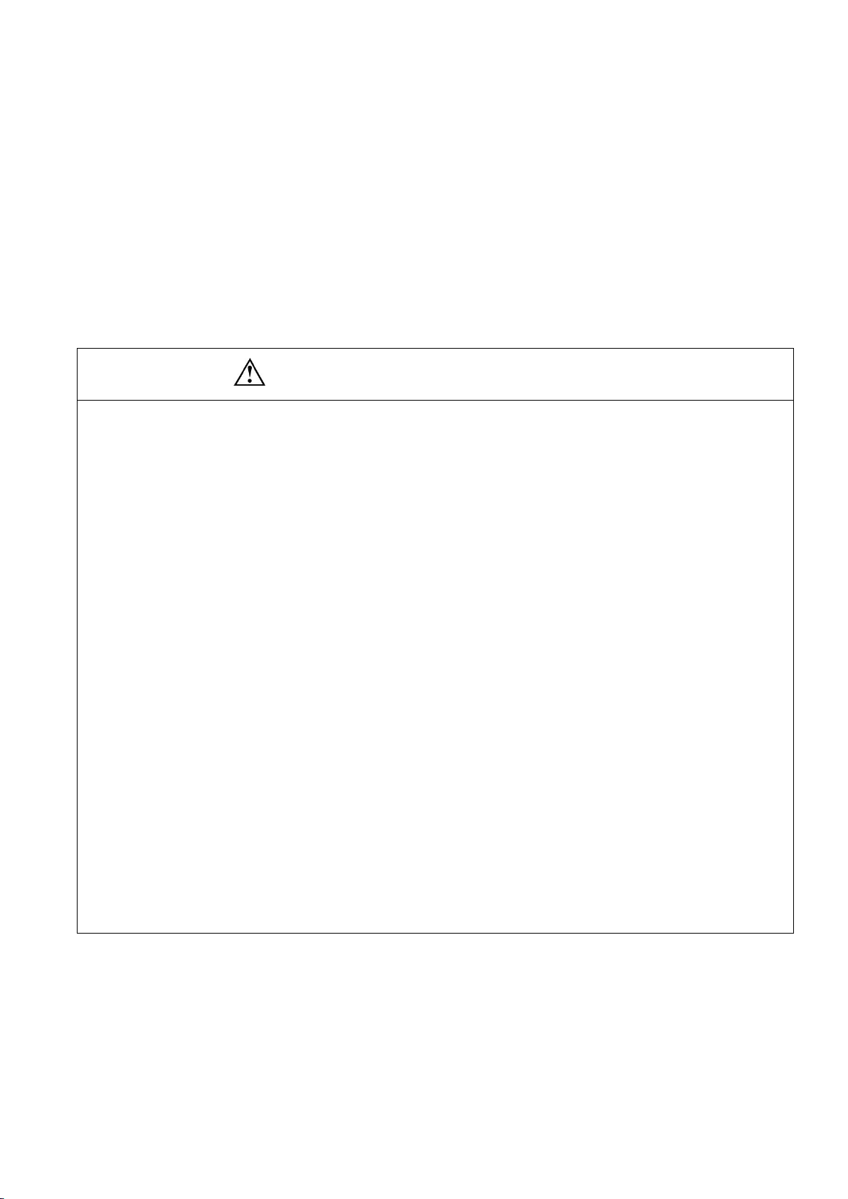
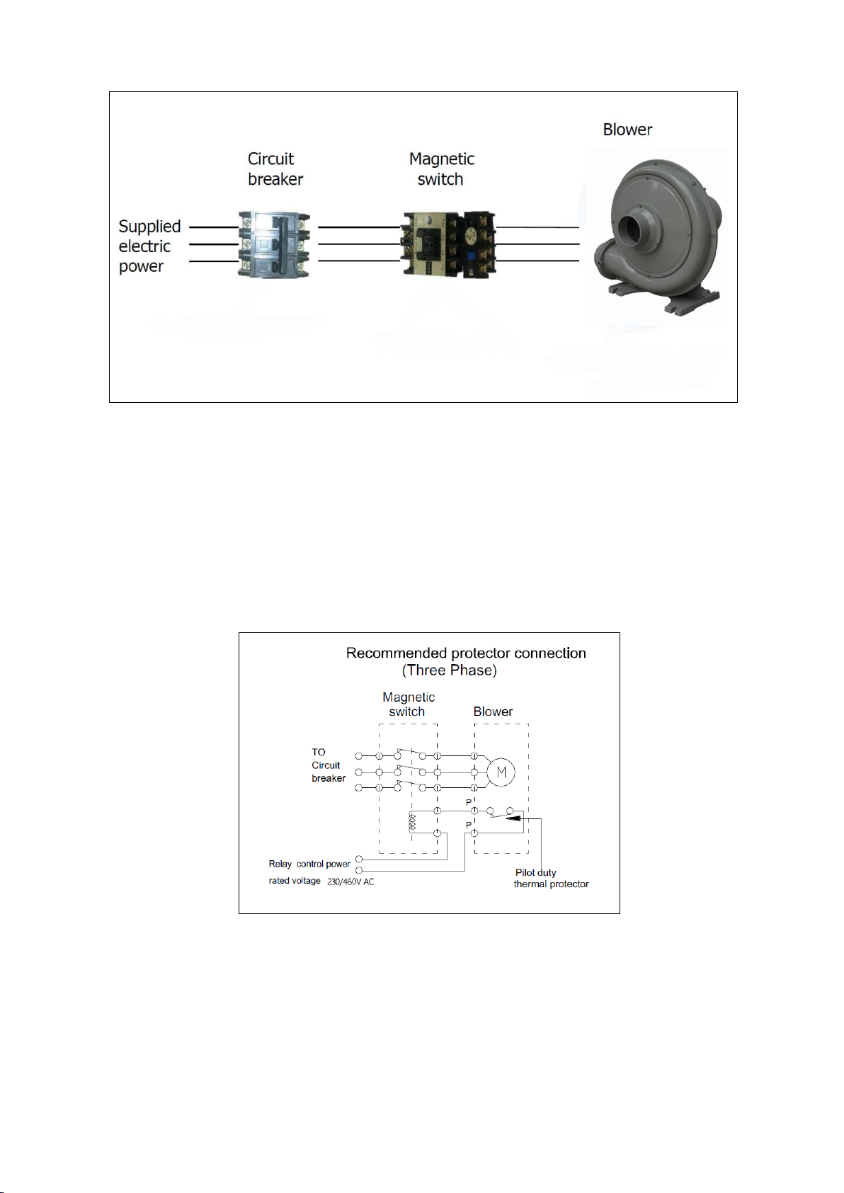
1.12 Pilot type of thermal protector is provided. This protector should be externally
connected with a magnetic switch which is used to control the power imput ON/OFF.
1.13 This device is designed for continuous operation , in case of non-continuous
running or high ambient temperature, checking suitability(maximum permissible
temperature)with the representatives of manufacturer.

3
2.Installation
2.1 Installation precautions:
2.2.1 To avoid vibration, the unit must be mounted on a rigid base.
2.2.2 Any flammable materials must be kept away from the unit.
2.2.3 Air and gases should be filtered before entering the intake by an intake or
inline filter.
2.2 Electric Connection:
WARNING: No connecting work is allowed before the electric power is
disconnected.

4
2.2.1 Choose the correct circuit breaker to match the motor’s rated current.
2.2.2 We recommended when using the magnetic switch, the setting value of electric
current is the motor’s rated current of 0.91 times.
2.2.3 Thermal protectors connection:
2.2.4 The ground wire must be connected to the grounding terminal.
2.2.5 The lead wires must be connected according to the diagram attached on the
terminal box.

5
Single Phase
50Hz/60HZ
100V~120V 200V~240V
Single Phase
50Hz/60Hz
200~240V
Three phase
50Hz 220V/380V
60Hz 230V/400V
Three phase
60Hz 230V/460V 380V/760V
Three phase
50Hz 220V/440V
60Hz 230V/460V
Note:The blower rotation is
judged from the motor side.

6
Fuji Model:
FUJI Model
Voltage(V)
Phase(PH)
Frequency(Hz)
HP
FDC-005A-7W
230/460
3
60
0.5
FDC-010A-7W
230/460
3
60
1
FDC-020A-7W
230/460
3
60
2
FDC-030A-7W
230/460
3
60
3
FDC-050A-7W
230/460
3
60
5
FDC-005P-5T
115/230
1
60
0.5
FDC-010P-5T
115/230
1
60
1
FDC-020P-2T
230
1
60
2
3 Operation:
3.1 These devices must be rotated as the “Arrow”direction marked on the casing.
3.2 For three phase, changing direction can be done by exchanging any two of the
connected wires.
3.3 These devices should be operated with the rated current and pressure within the
permitted range listed in the nameplate of the motor.
3.4 After wiring has been completed, reconfirm the rotation direction is same as arrow
marked on the casing.
3.5 Changing the outlet direction
3.5.1 If the discharge direction is not requested , our standard model ( FDC-005A-7W

7
---FDC-050A-7W) is shipped with the following charts as L1.
(FDC-075A-7W---FDC-010A-7W) is shipped with the following charts as R1. The outlet
direction of all blowers can be changed as showed on the chart.
FDC-005A-7W/FDC-010A-7W/FDC-020A-7W
Blower set
Motor set
bottom
up
top
1
2
3
R
1
2
3
L
FDC-030A-7W/FDC-050A-7W/FDC-075A-7W/FDC-100A-7W
Blower set
Motor set
bottom
up
top
1
2
3
R
1
2
3

8
L
Blower set
Motor set
45°angle
135°angle
225°angle
4
5
6
R
4
5
6
L
3.5.2 Directions for changing outlet direction:
Remove the casing bolts and casing cover.
Rotate the housing to the desired position.
Re-assemble with casing bolts for final
configuration.
Caution
Never disassemble the motor. If a malfunction occured after changing
the outlet direction, Please contact with your nearest sales office.

9
4 Trouble-shooting:
Troubles
Possible Cause
Remedy
Impeller
does not
turn
Humming
sound
1. One phase of line not connected
2. One Phase of stator winding open
3. Bearings defective
4. Impeller jammed by foreign material
5. Impeller jammed against housing or
cover
1. Connect
2. Contact Factory
3. Change bearings
4. Clean
5. Adjust
No sound
1. Two phases of power line not
connected.
2. Two phases of stator winding open
1. Connect
2. Contact factory
Impeller
turn
Blown fuse
1. Insufficient fuse capacity
2. Short circuit
1. Use fuse or proper
rating
2. Repair
Motor
overheated
or protector
trips
1. High or low voltage
2. Operating in single phase condition
3. Bearing defective
4. Impeller rubbing against housing or
cover
5. Impeller or air passage clogged by
foreign material
6. Unit operating beyond performance
range
7. One phase of stator winding short
circuited
1. Check input voltage
2. Check connections
3. Change bearings
4. Adjust
5. Clean
6. Contact factory
7. Contact factory
Abnormal
sound
1. Impeller rubbing against housing or
cover
2. Impeller or air passages clogged by
foreign material
3. Bearings defective
1. Adjust
2. Clean
3. Change bearings
Performance
below
standard
1. Leak in piping
2. Piping and air passages clogged
3. Impeller rotation reversed
4. Leak in blower
5. Low voltage
1. Tighten
2. Clean
3. Check wiring
4. Tighten cover,
flange
5. Check input voltage

10
8. Parts List
FDC-005A-7W----FDC-050A-7W
Fig .No.
Name of part
Fig. No.
Name of part
1
Inlet flange
23
Fan cover
2
Net
24
Terminal box cover
3
Casing cover-front
25
Gasket- T.Box cover
4
O-ring(0.5HP-3HP)
26
Terminal plate
5
Nuts
27
Terminal box
6
Spring washer
28
Cable gland
7
Impeller
29
Gasket-terminal box
8
Pin
30
Outlet flange
9
Casing
31
Gasket-outlet flange
10
O-ring
1-1
Bolt (Inlet flange)
11
Casing cover-rear
3-1
Bolt (Casing cover-front)
12
Foot
11-1
Bolt (Casing cover-rear)
13
O-ring
12-1
Bolt (Foot)
14
Oil seal-front
15-1
Bolt (Motor shield)
15
Motor shield
20-1
Bolt (Rear housing)
16
Bearing-front
23-1
Bolt (Fan cover )
17
Frame stator
24-1
Bolt (Terminal box cover)
18
Rotor& shaft assembly
26-1
Bolt (Terminal plate)
19
Bearing -rear
27-1
Bolt (Terminal box)
20
Rear housing
30-1
Bolt (Outlet flange)
21
Oil seal-rear
22
Fan

11

12
FDC-005P-5T----FDC-020P-2T
Fig .No.
Name of part
Fig. No.
Name of part
1
Inlet flange
24
Terminal box cover
2
Net
25
Gasket- T.Box cover
3
Casing cover-front
26
Terminal plate
4
O-ring
27
Terminal box
5
Nuts
28
Cable gland
6
Spring washer
29
Gasket-terminal box
7
Impeller
30
Outlet flange
8
Pin
31
Gasket-outlet flange
9
Casing
32
Band-Capacitor
10
O-ring
33
Capacitor
11
Casing cover-rear
1-1
Bolt (Inlet flange)
12
Foot
3-1
Bolt (Casing cover-front)
13
O-ring
11-1
Bolt (Casing cover-rear)
14
Oil seal-front
12-1
Bolt (Foot)
15
Motor shield
15-1
Bolt (Motor shield)
16
Bearing-front
20-1
Bolt (Rear housing)
17
Frame stator
23-1
Bolt (Fan cover )
18
Rotor& shaft assembly
24-1
Bolt (Terminal box cover)
19
Bearing -rear
26-1
Bolt (Terminal plate)
20
Rear housing
27-1
Bolt (Terminal box)
21
Oil seal-rear
30-1
Bolt (Outlet flange)
22
Fan
32-1
Bolt(Band-Capacitor)
23
Fan cover

13

14
Fuji Electric Corp of
America
50 Northfield Avenue
Edison. NJ 08837
Tel: 510-440-1060
Fax:201-368-8258
This manual suits for next models
8
Table of contents