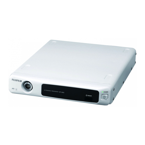
FujiFilm EP-6000 User manual

Processor
EP-6000 (FV693A)
Service Manual
SR1807-N002
Ver.1 Oct.2018

Target Model
Target model is elow.
Model
Name
Voltage
Frequency
Product
Code Serial No. Note
EP-6000 100-240V FV693A *V693K***
Destination:EU
Revised
date Details of revision Ver
Oct.2018 First version 1.00

SS1807-N002
Handling of this manual
A out this manual
■Scope
This service manual applies to the processor EP-6000 for endoscopes.
Precautions in handling this manual
1. The right to this manual elongs to FUJIFILM Corporation.
2. This manual shall not e used y any persons except those designated y FUJIFILM
Corporation or FUJIFILM Medical Co., Ltd.
3. Adequate measures shall e taken against unauthorized disclosure to or use y third parties of
this manual which includes confidential information of FUJIFILM Corporation.
4. Without prior written consent of FUJIFILM Corporation, e sure not to:
・Copy or reprint all or a part of this manual.
・Disclose, provide, loan or transfer all or a part of this manual to any other persons than a ove.
・Use all or a part of this manual for any other purposes than technical service of the device.
5. There may e some changes in this manual for improvement of the device.
6. The English version is the official version of this manual (except in Japan).

SS1807-N002
Notation in the manual
■ Indication of warning and caution
Warning
To e used where non-compliance with this warning may result in death or serious injury.
Caution
To e used where non-compliance with this caution may result in minor or moderate injury
and in serious damage (irrepara le or unrecovera le) of the device.
◆Instruction◆
To e used where non-compliance with this instruction may result in damage or failure of the
device.
◆Note◆
To e used where caution is required in performing the operational procedures.
◄ Reference ►
To e used for explanation of terms or supplementary explanation.

SS1807-N002 General Ta le of Contents - 1/1
General Ta le of Contents

SS1807-N002 General Ta le of Contents - 2/8
Service Manual .......................................... 1
Handling of this manual ........................... 3
A out this manual .............................................................................................................. 3
Precautions in handling this manual .................................................................................. 3
Notation in the manual ....................................................................................................... 4
General Ta le of Contents ....................... 1
Caution in Safety ....................................... 1
1. Safety Cautions ...................................................... 2
1.1 Infection Related Caution ............................................................................................ 2
1.2 General Caution .......................................................................................................... 5
2. La el ...................................................................... 6
2.1 EP-6000 La eling Layout (FV693A) ............................................................................ 6
2.1.1 La eling chart ........................................................................................................ 6
2.1.2 La eling A .............................................................................................................. 7
2.1.3 La eling B .............................................................................................................. 9
2.1.4 La eling C ............................................................................................................ 10
2.1.5 La eling D ............................................................................................................ 11
Product Specifications ............................. 1
1. EP-6000 Specifications .......................................... 2
1.1 Basic Specifications ..................................................................................................... 2
1.1.1 Catalog Specifications............................................................................................ 2
1.2Detailed specifications .................................................................................................. 3
1.2.1 Mechanical specifications ...................................................................................... 3
1.2.2 Electrical specifications .......................................................................................... 3
1.2.3 Chemical specifications ......................................................................................... 4
1.2.4 Accessories ............................................................................................................ 5
1.3 Functions ..................................................................................................................... 5
1.3.1 Button, switch, display ........................................................................................... 5
1.3.2 Peripherals ............................................................................................................. 5
1.3.3 Functions realized when working with scope ......................................................... 6
1.3.4 Display functions .................................................................................................... 6
1.3.5 Internal interface .................................................................................................... 6
1.3.6 Counter .................................................................................................................. 6
1.3.7 Internal clock .......................................................................................................... 6
1.3.8 Memory .................................................................................................................. 6
1.4 Auxiliary functions ........................................................................................................ 7
1.5 Quality ......................................................................................................................... 7
1.6 Regurations ................................................................................................................. 8
1.7 Block Diagram ............................................................................................................. 9
2. Disposal ...............................................................10
3. Change History .................................................... 11
3.1 ECN Pu lication History ............................................................................................ 11
3.2 Software Version History ........................................................................................... 11

SS1807-N002 General Ta le of Contents - 3/8
Instruction of System ............................... 1
1. Security .................................................................. 2
1.1 Category ...................................................................................................................... 2
1.2 Log in / Logoff .............................................................................................................. 3
1.2.1 Login ...................................................................................................................... 3
1.2.2 Logoff ..................................................................................................................... 4
1.3 Password Change ....................................................................................................... 5
1.3.1 Password change for “User” and “Administrator” ................................................... 5
1.3.2 Password change for “Service” .............................................................................. 6
2. System Configuration ............................................. 7
2.1 Display ................................................................. 8
2.1.1 Screen Display Setup ............................................................................................ 9
2.1.1.1 Patient Information Screen ............................................................................. 10
2.1.1.2 Data Display Type (PC).................................................................................. 11
2.1.1.3 Data Display Type (TV) .................................................................................. 16
2.1.2 Error Message Display......................................................................................... 19
2.1.3 P in P Setup ......................................................................................................... 19
2.1.4 Data Display Switch ............................................................................................. 20
2.2 Basic Setup ............................................................................................................... 21
2.2.1 Display Warning ................................................................................................... 22
2.2.1.1 Iris Timer ........................................................................................................ 22
2.2.1.2 Warning Display at End of Exam .................................................................... 22
2.2.1.3 when Pat. ID is not entered ............................................................................ 22
2.2.2 Freeze Setup ....................................................................................................... 23
2.2.3 Foot Switch .......................................................................................................... 24
2.2.3.1 Foot switch Setup ........................................................................................... 24
2.2.3.2 Functions to e Assigned to the Foot Switch ................................................. 25
2.2.4 Remote Setup ...................................................................................................... 27
2.2.5 Information Output ............................................................................................... 28
2.2.6 Patient Information ............................................................................................... 29
2.2.6.1 Entry Method Setup ....................................................................................... 29
2.2.6.2 Padding Setup ................................................................................................ 29
2.2.6.3 Automatic Age Calculation ............................................................................. 30
2.2.6.4 Doctor List Auto Search ................................................................................. 30
2.2.7 Security ................................................................................................................ 31
2.2.7.1 Serviced ......................................................................................................... 31
2.2.7.2 Factory ........................................................................................................... 31
2.3 Light source ............................................................................................................... 32
2.3.1 Light Source ......................................................................................................... 33
2.3.1.1 Light emitting time .......................................................................................... 33
2.3.1.2 LGDET ........................................................................................................... 33
2.4 Endoscope................................................................................................................. 34
2.4.1 Scope Color ......................................................................................................... 35
2.4.1.1 Scope Color Auto Adjust ................................................................................ 35
2.4.1.2 Scope Color Manual Adjust ............................................................................ 38
2.4.2 Scope Function .................................................................................................... 40
2.4.2.1 S600 Correction ............................................................................................. 40
2.4.2.2 Zoom Setup .................................................................................................... 40
2.4.3 Optical Zoom Setup ............................................................................................. 41
2.4.4 Electronic Zoom Setup......................................................................................... 42

SS1807-N002 General Ta le of Contents - 4/8
2.4.4.1 Electronic Zoom ............................................................................................. 42
2.4.4.2 Full Mask ........................................................................................................ 42
2.4.5 700 Scope Setup ................................................................................................. 43
2.5 Service ...................................................................................................................... 44
2.5.1 Color Bar .............................................................................................................. 45
2.5.1.1 Color Bar List ................................................................................................. 45
2.5.2 Software Version Upgrade ................................................................................... 46
2.5.2.1 Software Version Upgrade List ....................................................................... 46
2.5.3 Service Personnel Memo ..................................................................................... 47
2.5.4 Config file ............................................................................................................. 48
2.5.4.1 Store all configuration data in external memory ............................................. 48
2.5.4.2 Restore all configuration data from external memory ..................................... 49
2.5.4.3 Store common config data in external memory .............................................. 50
2.5.4.4 Restore common config data from external memory ...................................... 51
2.5.5 Log Setup ............................................................................................................ 52
2.5.5.1 Aoutomatic Log Save ..................................................................................... 52
2.5.5.2 Export error log file ......................................................................................... 52
2.5.6 Light Source & Scope Logging ............................................................................ 54
2.5.6.1 Export Light source log file ............................................................................. 54
2.5.6.2 Export 700 Scope log file ............................................................................... 55
2.5.7 Export error log file using the key oard ............................................................... 56
3.Peripheral Setup ...................................................59
3.1 Image Memory........................................................................................................... 60
3.1.1 Internal Memory ................................................................................................... 61
3.2 Network Setup ........................................................................................................... 62
3.2.1 Network Setup ..................................................................................................... 63
3.2.2 FTP Setup ............................................................................................................ 63
3.2.2.1 Ping(FTP) ...................................................................................................... 64
3.2.3 NTP setup ............................................................................................................ 65
3.2.3.1 Ping (NTP) ................................................................................................... 65
3.2.3.2 NTP check ...................................................................................................... 65
3.3 Printer ........................................................................................................................ 66
3.3.1 Printer Setup ........................................................................................................ 67
3.3.1.1 Printer Connection ......................................................................................... 67
3.3.1.2 Printer Setup .................................................................................................. 68
3.3.1.3 Digital Printer Setup ....................................................................................... 70
3.4 Recorder .................................................................................................................... 71
3.4.1 Still Recorder ....................................................................................................... 72
3.5 Others ........................................................................................................................ 73
3.5.1 Card Information Setup ........................................................................................ 74
3.5.2 Device Setting 1 ................................................................................................... 74
3.5.3 Device Setting 2 ................................................................................................... 74
4.Image Setup ..........................................................75
4.1 Image Setting ............................................................................................................ 76
4.1.1 Screen Display Setup .......................................................................................... 77
4.1.1.1 Zoom Ratio of Electronic Zoom ...................................................................... 77
4.1.2 Screen Display Setup .......................................................................................... 77
4.1.2.1 Color Mode ..................................................................................................... 77
4.2 Light Control .............................................................................................................. 78
4.2.1 Screen Display Setup .......................................................................................... 79
4.2.1.1 Brightness Limit for Auto Metering Mode ....................................................... 79
4.2.1.2 Brightness Adjustment for Peak Metering ...................................................... 79

SS1807-N002 General Ta le of Contents - 5/8
4.3 Basic setting .............................................................................................................. 80
4.3.1 Items Reset at Power-on ..................................................................................... 81
4.3.1.1 Screen for Setting Items Reset at Power-on .................................................. 81
5.Language Setup ....................................................83
5.1 Language Setup ........................................................................................................ 84
5.1.1 Key oard Setup ................................................................................................... 85
5.1.2 Built-in Language ................................................................................................. 85
5.1.3 Install Language .................................................................................................. 85
6.System Information ...............................................86
7.Setting of the Network ...........................................87
7.1 Outline ....................................................................................................................... 87
7.2 Description................................................................................................................. 89
7.2.1 Communication System ....................................................................................... 89
7.2.2 Connection ........................................................................................................... 89
7.3 Network Settings on the EP-6000.............................................................................. 90
7.4 Settings on the FTP Server ....................................................................................... 91
7.4.1 Settings on the FTP Server .................................................................................. 91
7.4.2 Setting the TCP/IP ............................................................................................... 91
7.5 Confirmation of Network Connection ......................................................................... 92
7.5.1 Confirmation of Ca le Connection (Confirmation of LED) .................................... 92
7.5.2 Confirmation of Ping ............................................................................................ 92
8. Software Version Upgrade ...................................93
8.1 Preparation ................................................................................................................ 93
8.2 Version upgrade procedure ....................................................................................... 93
8.3 Checking Version Up ................................................................................................. 95
9. EP-6000 Description of Configuration .................96
9.1 Block Diagram ........................................................................................................... 96
9.2 Schematic diagram .................................................................................................... 97
9.3 Connector pin layout .................................................................................................. 99
9.3.1 Scope connector (39 pins) ................................................................................... 99
9.3.2 DVI (DVI-I 24 pins) ........................................................................................... 100
9.3.3 Video (BNC) ..................................................................................................... 100
9.3.4 S-VIDEO(Y/C) Mini DIN 4 pins ......................................................................... 100
9.3.5 Analog RGB Mini DIN 15 pins ............................................................................ 101
9.3.6 RS-232C DSUB 9 pins .................................................................................... 101
9.3.7 Key oard USB-A type....................................................................................... 101
9.3.8 Card Reader USB-A type ................................................................................... 102
9.3.9 Remote1 / Remote2 BNC .................................................................................. 102
9.3.10 Foot SW DIN 5 pins ......................................................................................... 102
9.3.11 Ethernet RJ-45................................................................................................ 102
9.3.12 Printer USB-A type ........................................................................................... 102
9.3.13 WC-Link 37 pins .............................................................................................. 103
9.4 Outline of PCB roles ................................................................................................ 104
Failure Analysis......................................... 1
1. Trou leshooting ..................................................... 2
2. Error Message ....................................................... 3

SS1807-N002 General Ta le of Contents - 6/8
Checkup, Replacement and Adjustment . 1
1. Parts exchange procedure ..................................... 3
1.1 Procedures for Parts Replacement of EP-6000 ........................................................... 3
1.1.1 Top Cover .............................................................................................................. 3
1.1.2 Filter ....................................................................................................................... 6
1.1.3 Front Cover ............................................................................................................ 7
1.1.4 Power Switch ......................................................................................................... 9
1.1.5 Key Top Assy ....................................................................................................... 13
1.1.6 Small Cover Unit .................................................................................................. 14
1.1.7 One Connector plate Assy ................................................................................... 18
1.1.8 Light Source Unit ................................................................................................. 22
1.1.9 Air Guide Pipe ...................................................................................................... 27
1.1.10 Air Tu e .............................................................................................................. 29
1.1.11 Photo Interrupter ................................................................................................ 30
1.1.12 Harnes LG_PI-WOC .......................................................................................... 31
1.1.13 WOC PCB .......................................................................................................... 34
1.1.14 ELC PCB ........................................................................................................... 42
1.1.15 Pump ................................................................................................................. 46
1.1.16 Fan (Light source unit side) ............................................................................... 48
1.1.17 Fan (Power supply PCB side) ............................................................................ 51
1.1.18 Power Supply PCB ............................................................................................ 53
1.1.19 Noise Filter ......................................................................................................... 55
1.1.20 Inlet Assy ........................................................................................................... 57
1.1.21 Fuse ................................................................................................................... 60
1.1.22 EVE Connector .................................................................................................. 61
1.1.23 IO/LORES PCB ................................................................................................. 63
1.1.24 Main PCB ........................................................................................................... 65
1.1.25 Patient PCB ....................................................................................................... 77
1.1.26 USB PCB ........................................................................................................... 79
1.1.27 Rear Panel ......................................................................................................... 81
1.1.28 Harness IOL-OP ................................................................................................ 86
1.1.29 Harness ELC-OP ............................................................................................... 88
1.1.30 Front Frame ....................................................................................................... 90
1.1.31 Foot.................................................................................................................... 95
1.1.32 Key oard cover .................................................................................................. 96
1.2 EEPROM Writing Procedure ................................................................................... 100
1.2.1 PC Setup (performed only for the first time) ....................................................... 100
1.2.2 EEPROM Writing ............................................................................................... 102
1.3 Checking Procedures for Power Supply .................................................................. 105
1.3.1 Acquiring the scope log data .............................................................................. 105
1.3.2 Checking the Power Supply ............................................................................... 107
2. Operation confirmation after repair ....................108
2.1 Precautions.............................................................................................................. 108
2.1.1 Qualification for performing the Electrical Safety Test ........................................ 108
2.1.2 Dielectric Strength Test ...................................................................................... 108
2.1.3 Handling of tester ............................................................................................... 108
2.1.4 Connection with other equipments ..................................................................... 108
2.2 Preparation for Test ................................................................................................. 108
2.2.1 Checking the testers prior to the Test ................................................................. 108
2.2.2 Checking the testers already checked prior to the Test ...................................... 108
2.2.3 Saving of Customers' Config data ...................................................................... 109

SS1807-N002 General Ta le of Contents - 7/8
2.3 Electrical Safety Inspection ..................................................................................... 110
2.4 Operation check ...................................................................................................... 114
2.4.1 Appearance ........................................................................................................ 114
2.4.2 Function ............................................................................................................. 114
2.5 Check Sheet ...............................................
エラー! ブックマークが定義されていません。
2.6 Setting after Operation Confirmation ..........
エラー! ブックマークが定義されていません。
3. JIG/Equipment list ..............................................125
3.1 JIG list ..................................................................................................................... 125
3.2 Equipment List ......................................................................................................... 131
3.3 Check procedures ................................................................................................. 133
3.3.1 Torque driver ...................................................................................................... 133
3.3.1.1 Torque .......................................................................................................... 133
3.3.2 Manual inding tool ............................................................................................ 134
3.3.2.1 Tightening Torque ......................................................................................... 134
3.3.3 Electrical safety test/the plug and play force measurement jig .......................... 135
3.3.3.1 Interterminal Resistance Value ..................................................................... 135
3.3.4 Protective earth power ca le jig ......................................................................... 135
3.3.4.1 Resistance Value .......................................................................................... 135
3.3.5 Leakage current test Jig 500 Series ................................................................. 136
3.3.5.1 Resistance etween terminals ..................................................................... 136
3.3.6 Dielectric strength test Jig 500 Series .............................................................. 136
3.3.6.1 Resistance etween terminals ..................................................................... 136
3.3.7 Scope................................................................................................................. 137
3.3.7.1 Light Output .................................................................................................. 137
3.3.7.2 Dimming ....................................................................................................... 137
3.3.7.3 Picture Quality .............................................................................................. 137
Service Parts List ...................................... 1
Periodical Maintenance ............................ 1
1. Periodical Maintenance .......................................... 2
2. Cleaning ................................................................. 3
2.1 Filter ............................................................................................................................ 3
2.2 LG Connector Unit ....................................................................................................... 5
2.3 One Connector Unit ..................................................................................................... 5
3. Periodical checkup ................................................. 6
3.1 Storing procedures of Config Data ............................................................................... 6
3.2 Inspection Items .......................................................................................................... 7
3.2.1 Appearance ............................................................................................................ 7
3.2.2 Functions ............................................................................................................... 7
3.3 Check Sheet .............................................................................................................. 14
3.4 Restoring procedures of Config Data ........................................................................ 15
Installation ................................................. 1
1. System Installation ................................................. 2
1.1 Installation Flowchart ................................................................................................... 4
1.2 Installation onto the Cart (Standard System Installation Example) .............................. 5
1.3 Connecting the WC-LINK ca le ................................................................................... 9
1.4 Attaching the Dustproof Filter (Louver) ...................................................................... 10
1.5 Connecting the Monitor ............................................................................................. 11

SS1807-N002 General Ta le of Contents - 8/8
1.6 Connecting the Key oard .......................................................................................... 12
1.7 Installation for System Expansion .............................................................................. 13
1.8 Printer Connection (Remote System) ........................................................................ 15
1.9 Printer Connection (RS-232C System) ...................................................................... 17
1.10 Digital Printer Connection ........................................................................................ 18
1.11 Video Recorder Connection (Remote System) ........................................................ 19
1.12 Connecting the Power Source ................................................................................. 20
1.13 Power Source .......................................................................................................... 22
1.14 Connecting the Power Source When Using the Cart ............................................... 23
1.15 Basic Information on Power Cord ............................................................................ 24
1.16 Attaching the LAN connector guard when using a network ..................................... 24
2. Initial Settings at the Time of Installation .............25
2.1 Flowchart of System Settings at the Time of Installation ........................................... 25
2.2 Basic System Setup Operations ................................................................................ 26
2.3 Function Ta .............................................................................................................. 28
2.4 Display Ta ................................................................................................................ 31
2.5 Basic Setting Ta ....................................................................................................... 33
2.6 Light Source Ta ....................................................................................................... 35
2.7 Endoscope Ta ......................................................................................................... 36
2.8 Setting Foot Switch (FS1) .......................................................................................... 47
2.9 Setup for Switching the Shutter Speed During Optical Zoom .................................... 50
2.10 Setting the Doctor's Name ....................................................................................... 50
2.11 Setting the Procedure Name .................................................................................... 56
2.12 Setting the Message ................................................................................................ 60
3. Security Function .................................................64
3.1 Access Control with the Security Function ................................................................ 65
3.2 Logging in to the Security Function (Changing the Password) .................................. 66
3.3 Logging off the Security Function .............................................................................. 68

SS1807-N002 Caution in Safety - 1/12
Caution in Safety

SS1807-N002 Caution in Safety - 2/12
1. Safety Cautions
In this chapter, general precautions to prevent hazard to human ody and serious accident during
maintenance, such as installation and periodic inspection, are descri ed.
During actual maintenance, this manual as well as the procedures and precautious statements in
the following documents should e o served:
・Precautious la els adhered to the equipment.
・The attached documents and operation manual for this equipment.
1.1 Infection Related Caution
■Precautions in taking products out of a customer’s facilities
Any items or products to e carried ack for repair must e handled as contaminated.
Accept a request for their repair after they have een disinfected or sterilized at the customer’s
facilities.
Separate infected repair items from disinfected or sterilized ones.
If items not disinfected are taken out, e sure to put and seal them in dou le plastic ags, and
clearly indicate ”Not disinfected” on the ag. If lood has een attached to them, put and seal
them in dou le plastic ags to prevent secondary infection, and clearly indicate ”Blood attached”
on the ag. Pack such items only. If any other items or documents are carried ack together
with such items, pack them in a carton separately from the non-disinfected or lood-attached
items.
Visit to the customer's site
Disinfection
Remove adherent matters
Found Not found
Disinfection
Preparation for carrying out products
(Packing: dou le)
Preparation for carrying out products
(Packing: normal)
Create a request sheet for repair
Descri e "Blood, etc. adhered" Create a request sheet for repair
Carry out
Check the
presence/a sence of
adherent matters such
as lood

SS1807-N002 Caution in Safety - 3/12
■ Handling products with suspicion of contamination at outside medical facilities
Maintenance should e implemented with particular attention to the following points:
・If there is a local standard and/or regulation for pollution a atement, please comply with that
standard and/or regulation.
・Wear protective clothing and gears during maintenance such as white gown, safety goggles,
mask and gloves.
・Do not carelessly touch human ody with gloved hand during maintenance. (Eyes need special
attention)
・If there is special concern on health, change a field service engineer.
・Wash hands thoroughly after maintenance.
・Contaminated products such as protective equipments and tools after a maintenance should
e pack in plastic ags and sealed, and taken way ( rought ack).
・If there is a suspicion of accident, contact a manager immediately.
■ Handling returned products from the market with suspicion of contamination.
Disinfect everything which has contact with products.
1) Preparation
・Disposa le work cloth such as white gown (to e worn)
・Eye protector such as safety goggles (to e worn)
・Disposa le gloves (to e worn)
・Disposa le mask (to e worn)
・Hand antisepsis such as WELPAS (for hand disinfection)
・Ethanol (for disinfection)
◆Precaution◆
Fundamentally, use ethanol with 70% density.
・Gauze etc. (for wiping the equipment)
・Plastic sheet etc. (for covering under the workspace for wiping the equipment)
2) Disinfecting procedure
・Wear protectors such as white gown, safety goggles and gloves.
・Lay plastic sheet under the work place where the equipment is to e disinfected.
・Disinfect the target equipment with ethanol soaked gauze.
・Dispose used items such as gloves, mask, gauze and plastic sheet in separate plastic ags
(Precaution).
・Disinfect hand with WELPAS etc. after washing.
◆Precaution◆
Dispose used items such as gloves, mask, gauze , plastic sheet as “infectious wastes”.

SS1807-N002 Caution in Safety - 4/12
Found Not found
Not found
Found
Possi le
Impossi le
Repair is
possi le
Repair is
impossi le
Reception
Replace parts with lood, etc.
adhered
Make an inquiry to the
manufacturer
with a prior notice
Normal repair
Report that repair is impossi le
Return products not repaired
Check the report of adherent
matters such as lood
Check the presence/a sence of
intruding matters in the machine
Remove the intruding matters
Possi le/impossi le check
Remove adherent matters
(Replace parts with lood, etc.
adhered)
Manufacturer
Judgment on repair

SS1807-N002 Caution in Safety - 5/12
1.2 General Caution
■ Power supply
・Do not attach / remove parts while power is distri uted.
If a ove procedure is implemented with power distri ute, it may cause electric shock or short
circuit.
・There are some parts with insufficient electric discharge after turning power off, such as power
supply parts and parts in high temperature (lights), should not e touched.
・Extra attention should e paid for adjustment and inspection with power distri uted to prevent
from electric shock and short circuit.
・Do not saturate power cord and plug, and connect plug with wet hand.
It may cause electric shock and short circuit.
■ PCB
Static protection wrist and should e worn and human ody should e grounded for PCB
maintenance.
Static electrocution in human ody may cause damage of electric parts on PCB.
■ Always attach ungrounded parts and fixing screws, protective earth conductor, and power-supply
cord as the way they were.
It may cause failure to form protective earth circuit and may result in electric shock.
■ Safety interlock
Safety interlocks such as fuse, interlock switch and cover should in active states at all time.
■ Rotating parts
Never touch rotating parts
Also pay extra attention to not to catch ody part such as hand, leg, hair and cloth into a rotating
equipment.
■ Parts exchange
・ If parts are damaged and/or worn, exchange them with the parts designated in this manual.
■ La eling
・ Do not remove la els adhered on the equipment(rating plate, caution la el and instruction la el)
unless designated in this manual.
■ Handling personal information when products are taken away
When taking a product away from customer, delete private information such as patient data saved
in the equipment with customer’s approval.
Fundamentally, do not take media, such as MO disk and Compact Flush, with saved video print
and image file that people can e identified from customer.

SS1807-N002 Caution in Safety - 6/12
2. La el
2.1 EP-6000 La eling Layout (FV693A)
2.1.1 La eling chart
D
B
A
C

SS1807-N002 Caution in Safety - 7/12
2.1.2 La eling A
No.
Description Layout
A1
Brand name
A
A2
RF electromagnetic energy
A3
Scope Connector Socket Mark
Light guide
A4
BF Mark
A5
Refer to instructions
A9 Scope Connector Socket Mark
Electrical signal
A6
Power supply mark
A10
External memory
A7
Power switch mark
A11
Model name
EP-6000
A8
Arrow・Index Mark
A12
Operation Panel Mark
12
11
6
1
3
4
2
10
5
8
4
9
7

SS1807-N002 Caution in Safety - 8/12
No.
Description Layout
A13
Manufacturer and address
A
A14
Represented and address
A15
GS1 Data Matrix
Product serial No., date of manufacture,
and GS1 Data Matrix are changed each
time.
A16
Caution La el
(01)**************
(11)YYMM01
(21) *V693****
13
16
14
15
This manual suits for next models
1
Table of contents
Other FujiFilm Computer Hardware manuals
Popular Computer Hardware manuals by other brands

DigiSpider
DigiSpider CNP888 product manual

IEI Technology
IEI Technology WAFER-JL-N5105 Quick installation guide

Inovonics
Inovonics MAP II 231 instruction manual

Intel
Intel RS2PI008 Quick start user guide

Brainboxes
Brainboxes BL-500 installation guide

Telit Wireless Solutions
Telit Wireless Solutions ME50-169 user guide