FujiFilm XA77x9.5BESM-S35 User manual

XA77×9.5BESM-S35
2F
BB00035610-102
LP510A-S35 2807
富士能电视镜头


In the European Union, Norway, Iceland and Liechtenstein:
This symbol on the product, or in the manual, and/or on its packaging indicates
that this product shall not be treated as household waste. Instead it should be
taken to an applicable collection point for the recycling of electrical and
electronic equipment.
By ensuring this product is disposed of correctly, you will help prevent potential negative
consequences to the environment and human health, which could otherwise be caused by
inappropriate waste handling of this product.
Disposal of Electrical and Electronic Equipment in Private Households

SM-48-T1/R1 - i -
目 次
■安全にお使いいただくために ····················· ⅱ
■ご使用の前に········································ ⅴ
・カメラへ取り付ける前に ························ ⅴ
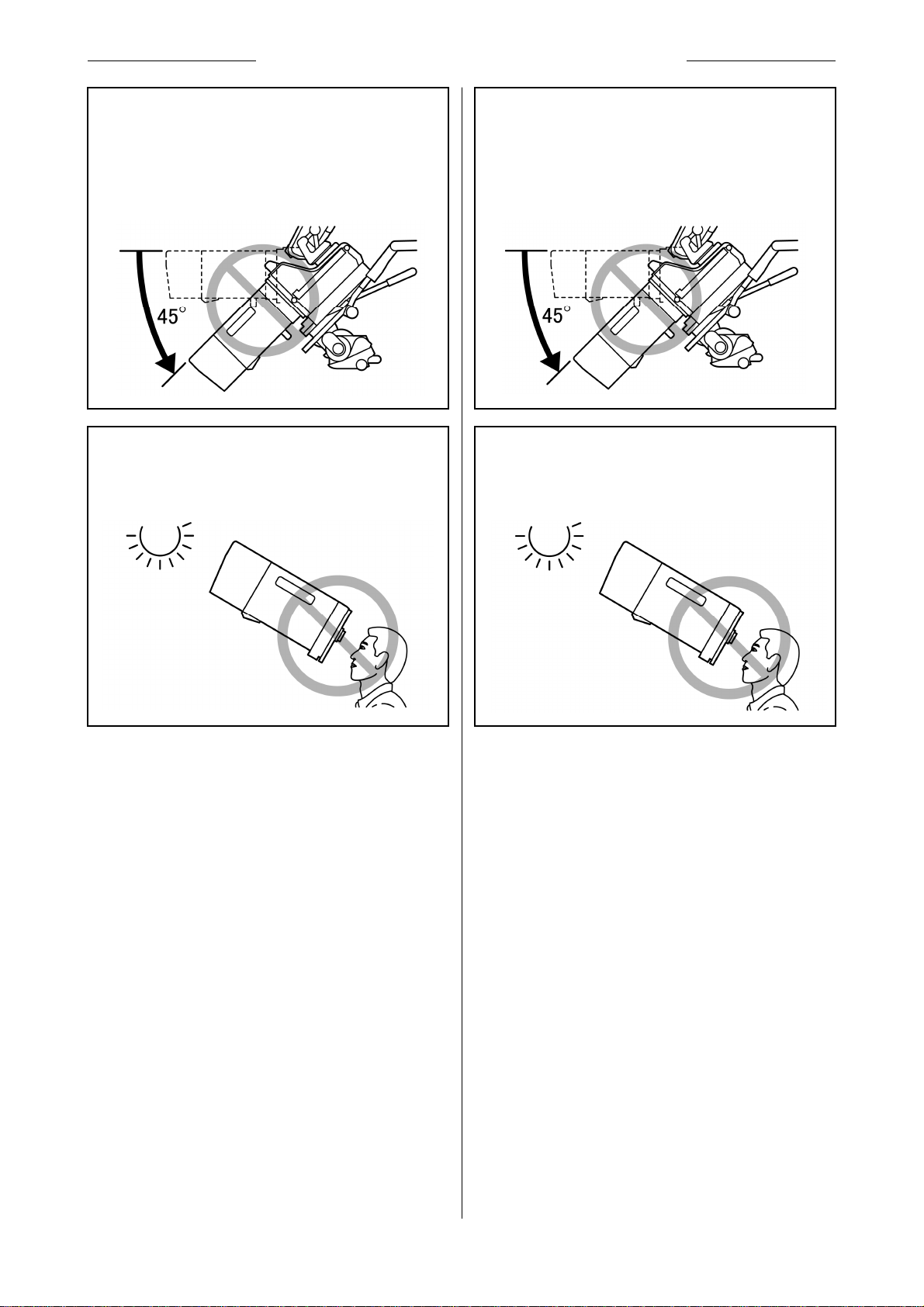
・レンズサポータご使用時の注意 ·············· ⅴ
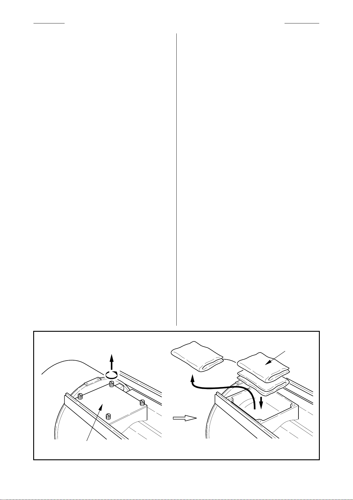
・乾燥剤の収納 ···································· vi
・カメラの選択 ····································· vii
・カメラモードの設定······························viii
■ 概 説 ···················································1
■ 商品構成 ···············································1
■ 仕 様 ···················································2
■ 各部の名称と機能 ····································3
■ 取付方法 ···············································7
■フランジバックの調整·································8
■ 操作方法 ············································· 11
◇
1フォーカス操作···································· 11
◇
2ズーム操作········································ 12
◇
3アイリス操作 ······································ 12
◇
4エクステンダ切替操作··························· 12
◇
5マクロ操作········································· 13
■アイリスアンプの調整 ······························ 14
■画角変化補正機能について ······················ 15
■ 保守 ・点検 ·········································· 16
◇
1日常の整備········································ 16
◇
2水分の除去········································ 17
◇
3レンズの保管······································ 17
◇
4点 検··············································· 17
■オプショナルアクセサリ ···························· 18
■エンコーダ出力信号仕様 ·························· 25
CONTENTS
■FOR YOUR SAFETY USE ··························ⅱ
■PRIOR TO USE ······································ⅴ
・BEFORE INSTALLING ONTO CAMERA ·····ⅴ
・CAUTION WHEN USING THE LENS
SUPPORTER ·····································ⅴ
・ENCLOSURE OF DESICCANT ················ vi
・SELECTION OF CAMERA······················vii
・SETTING OF CAMERA MODE ··············· viii
■ GENERAL DESCRIPTION··························· 1
■ LIST OF COMPONENTS ···························· 1
■SPECIFICATIONS ···································· 2
■ NAMES AND FUNCTIONS·························· 3
■INSTALLATION ······································· 7
■ADJUSTMENT OF FLANGE FOCAL LENGTH ·· 8
■OPERATING INSTRUCTION ······················11
◇
1FOCUSING OPERATION ························11
◇
2ZOOMING OPERATION ·························12
◇
3IRIS OPERATION ·································12
◇
4EXTENDER SELECTION ························12
◇
5MACRO OPERATION ····························13
■ADJUSTMENT OF IRIS AMPLIFIER ·············14
■ABOUT FUNCTION OF COMPENSATION
FOR CHANGE OF FIELD ANGLE·················15
■ MAINTENANCE ······································16
◇
1DAILY MAINTENANCE···························16
◇
2ELIMINATION OF WATER·······················17
◇
3STORAGE OF LENS ·····························17
◇
4INSPECTION·······································17
■ OPTIONAL ACCESSORIES ·······················18
■SPECIFICATIONS OF
ENCODER OUTPUT SIGNAL······················25

安全にお使いいただくために FOR YOUR SAFETY USE
E1462/R4 - ii -
This content explains important notices for all the users
to use this product safely. Read the content carefully
before using, and follow the instructions.
The following signs show:
△ WARNING
ここでは、製品を安全に正しくご使用いただくために、重
要な注意事項を説明しています。必ずご使用前に読
み、記載内容に従って正しくご使用ください。
文章中の表示は次のことを表しています。
△警 告
△警告 誤った取り扱いをしたときに、人が
死亡または重傷を負う可能性が想
定される内容を示します。
△注意 誤った取り扱いをしたときに、人が
傷害を負ったり、物的損害の発生
が
想定
される
内容
を
示
し
ます
。
△WARNING
Indicates the possibility of causing death or
serious injury when misused.
△ CAUTION
Indicates the possibility of causing injury or
substantial damage when misused.
安全にお使いいただくために FOR YOUR SAFETY USE
◆ レンズの内部に水が入らないようにしてください。
火災や感電の原因となります。
万一水が入ったときは、すぐにレンズに供給して
いる電源を切ってください。
◆ レンズには、規定の付属品以外の物を取り付けな
いでください。また、レンズの上には物を載せない
でください。操作時に落下して、重大な事故の原
因となります。
◆ Do not moisten inside of the appliances. It may
cause fire or electric shock. If the incident occurs,
shut off the power supplied to the lens
immediately.
◆ Do not attach something to the lens other than
Fujinon optional accessories that are designed to
be attached to the lens; do not put something on
the lens. An abnormal object attached to or on the
lens may fall in operation of the camera causing a
serious accident.
してはいけない「禁止」の内容を示し
ます。
Indicates what the user “should not
do.”

安全にお使いいただくために FOR YOUR SAFETY USE
E1462/R4 - iii -
◆ Be sure to attach all the parts securely. Dropping
any parts from a height may cause severe accidents.
◆ Before operating the camera, confirm that there is no
object in the range of camera movement. If the lens
is bumped against an object with a strong force, there
may be a case that the lens falls from the camera
causing a serious accident.
△ CAUTION
◆ Take care when carrying the lens. Dropping the lens
while carrying may cause injury.
◆ Before supplying the power to the lens, make sure all
the parts are connected correctly.
◆ In order to install or release the lens cable, be sure to
hold the joint part. Do not damage the cable by
gripping. It may cause fire or electric shock.
◆ 取り付け・締め付けは確実に行ってください。高所使
用時の落下は重大な事故の原因となります。
◆ カメラを操作するときは、カメラの動作範囲内に障害
物がないか、操作の前に確認してください。レンズが
障害物に強い衝撃で当たると、カメラより落下して重
大な事故の原因となります。
△注 意
◆ 運搬中の落下は、けがの原因となります。落とさない
ように注意してください。
◆ レンズに供給する電源は、各機器が正しく接続され
ていることを確認した後に入れてください。
◆ ケーブルを着脱するときは、必ずコネクタ部分を持っ
てください。ケーブルを傷つけると、火災や感電の原
因となります。
◆ レンズをカメラに取り付けた状態で、カメラを下方
に45゜以上傾けないでください。レンズがカメラより
落下して、重大な事故の原因となります。上記の
姿勢で撮影をする必要がある場合には、落下防
止のための処置をレンズに施してください。
◆ 太陽や高輝度の光源をレンズを通して見ない
でください。目に障害を負う原因となります。
◆ If the camera is declined by 45 degrees or more,
there may be a case that the lens installed on the
camera falls. If it is required to shoot an object
with the camera in the posture stated above,
before using the camera, a proper measure should
be taken on the lens to avoid falling.
◆ Do not look at any sorts of strong illuminant such
as the sun through the lens. Eyes could be
harmed.

安全にお使いいただくために FOR YOUR SAFETY USE
E1462/R4 - iv -
◆ If any sorts of incidents such as unusual smoke,
noise, smell or obstacles are found, shut off the
power supplied to the lens and pull out the lens cable
immediately. Please notify the sales agent from which
you purchased the lens.
◆ Do not remodel the product: it may impair the
functions of product or cause electric shock.
NOTICE
◆ Lens and its accessories are extremely precise
instrument, then be sure not to apply the strong
impacts to them. If the lens is of a type in which the
rear lens protrudes from the flange surface of the lens
mount, be sure not to apply impact to the lens part
when installing or releasing.
◆ There may be a case that the glasses of the lens mist
when the lens is carried from a cool place to a place
of high temperature and high humidity. To avoid a
mist on the glasses, before moving the lens, let the
lens adjust to the ambient temperature of the place
where the lens will be used.
◆ Be sure not to apply impact to the front part of the
lens when operating the camera.
◆ Put the cap on the lens while the camera is not used.
◆ If an accessory to be attached to the lens is equipped
with a mechanical drive relaying part, before
attaching it, check the joint part and get rid of all
obstacles. If there are any unusual conditions, please
contact the sales agent from which you purchase the
product.
◆ When the lens is used in the weather of fog, raining,
or snowing, cover up the lens to prevent it from the
water.
◆ To minimize the impact to the lens in transportation,
set the zoom to the wide end and the focus to the
infinity side end before releasing the lens from the
camera.
◆ 発煙・異常音・異臭・異物混入などの異常のときは、
すぐにレンズに供給している電源を切ってからレンズ
をカメラから取り外してください。その後、購入先販売
店にご連絡ください。
◆ 分解・改造を行わないでください。製品の機能を損
ねたり、感電の原因となります。
一般的な注意
◆ レンズおよびその付属品は精密機械です。決して強
い衝撃を与えないでください。
レンズマウントのフランジ面より後方にレンズ部分が
突き出ているレンズの場合、取り付け・取り外しの際、
レンズ部分に衝撃を与えないよう十分に注意してくだ
さい。
◆ レンズを寒いところから急に、気温と湿気が高いとこ
ろに持ち込むと、レンズが曇ることがあります。上記の
ような環境へレンズを持ち込むときは、前もってレン
ズを使用環境温度へ適合させるなどの曇り対策を講
じてください。
◆ カメラを操作するときは、レンズの前部に衝撃を与え
ないよう十分に注意してください。
◆ カメラを使用しないときは、レンズにはレンズキャップ
を取り付けてください。
◆ 駆動伝達部がある付属品を取り付ける場合、かみ合
い部分の形状に異常はないか、異物の付着はない
か十分に点検してください。異物があるときは確実に
取り除いてください。形状に異常があるときは、購入
先販売店にご相談ください。
◆ 濃霧・降雨・降雪などの環境で使用するときは、覆い
をするなどの対策をして、製品に水分がかからないよ
うにしてください。
◆ 輸送時のレンズへの衝撃を最小限にするために、レ
ンズをカメラから取り外す前にズームはワイド端に、フ
ォーカスは無限遠側一杯の位置になるように設定し
てください。

ご使用の前に PRIOR TO USE
NT66-1 - v -
ご使用の前に PRIOR TO USE
■ Before Installing onto Camera
When it is required to install this lens on a Sony studio
camera (Ex. HDC-1000) or on a Sony large lens adapter
(Ex. HDLA-1500), remove the pin on the bayonet mount
of the lens, and attach it to the threaded hole in the
moun
t
frame. To install this lens on another camera,
reinstall the pin on its former position.
■ カメラへ取り付ける前に
このレンズを、ソニー製スタジオ用カメラ(HDC-1000等)、
またはソニー製大型レンズアダプタ(HDLA-1500等)に
取り付けるときは、レンズのバヨネットマウントにあるピン
を外し、マウント枠にあるねじ穴に取り付けてください。
他のカメラに取り付ける場合は、ピンを元の位置に戻し
てください。
ねじ穴
THREADED HOLE
ピン
PIN
■ Cautions when using the lens supporter
When using this lens with a Fujinon lens supporter
(ELH-*) attached, use a power source connecter (see
“Name and Function of Each Part”) to supply power
from the lens side. If power is not supplied, correct
operation may not occur.
■ レンズサポータご使用時の注意
このレンズをフジノン製レンズサポータ(ELH-*)に取り
付けて使用する際には、パワーソース用コネクタ(“各部
の名称と機能”参照)からレンズ側に電源を供給して下
さい。電源を供給しない場合、正常動作しないことがあ
ります。

ご使用の前に PRIOR TO USE
NT01-2(A) - vi -
■ Enclosure of Desiccant
The inside of this lens is able to enclose desiccant in
order to eliminate humidity that may mist the surfaces
of the internal glasses. A desiccant bag for storage was
enclosed in the desiccant enclosure place before
shipment at the factory. Prior to use, take out this bag
f
irst, and put new desiccant bags in that place as
follows:
a. There are five desiccant bags in the trunk. Take out
two of them to use. The rest should be used when the
exchange of the desiccant is required.
b. Loosen the two lens shroud attaching knobs on the
both sides of the lens. Draw the shroud towards the
front of the lens to detach it from the body.
c. Remove the four screws to take off the lid.
d. Take out the desiccant bag for storage.
e. Fold two new desiccant bags and put them in the
desiccant enclosure place.
f. Put the detached lid in its place and reinstall the four
screws. Finally, reinstall the lens shroud.
Note 1. Perform the above procedure in a dust-free
place.
Note 2. In a humid region, it is recommended to change
the desiccant bags two times a year. The
desiccant being jellied indicates the time when it
must be exchanged.
■ 乾燥剤の収納
本レンズは、レンズ内部の曇りの原因となる湿気を除去
する目的で、乾燥剤を収納する機構となっています。工
場出荷時には、あらかじめレンズ内に保存用の乾燥剤
を収納していますので、ご使用の前に以下の要領で新
しい乾燥剤と交換してください。
a.収納箱から乾燥剤を取り出します。乾燥剤は 5 袋入り
となっていますが、このうち 2 袋を使用します。残りは
次の交換の際に使用してください。
b.レンズ本体の両側にあるカバー取付つまみをゆるめ
ます。カバーを前方に引いて外してください。
c. 乾燥剤収納部の 4 本のねじを外し、ふたを取ります。
d. 収納されている乾燥剤を取り出します。
e. 新しい乾燥剤 2 つをそれぞれ 2 つ折りにし、収納部に
入れます。
f.ふたを取り付け直し、カバーを元に戻します。
注 1. 乾燥剤の収納は、ホコリのない場所で行ってくだ
さい。
注 2. 湿度の高い地域では、半年に一回程度の交換を
お勧めします。乾燥剤がゼリー状になると交換の
時期です。
乾燥剤収納部
DESICCANT ENCLOSURE PLACE
新しい乾燥剤
NEW DESICCANT BAG
保存用乾燥剤
DESICCANT BAG
FOR STORAGE

ご使用の前に PRIOR TO USE
NT58-2 - vii -
■ Selection of Camera
The behavior of the intercom select switch in an
accessory differs by types of camera. If required,
change the setting of dip switch (S710-7) on the
A-board in the lens according to the type of camera. At
the factory, the switch is set to “TYPE 1.”
The circuits relative to the dip switch are shown below.
■ カメラの選択
アクセサリのインターカム選択スイッチは、カメラの機種
により動作が異なります。レンズ内の A-ボード上に、カ
メラを選択するディップスイッチ (S710-7) がありますの
で、ご使用上不都合な場合には、このスイッチを切り替
えてください。なお、工場出荷時には、TYPE 1 に設定し
てあります。参考までに、下図に内部の接続を示しま
す。
Ⅰ. TYPE 1 CAMERA: BVP-270 series (NTSC) and BVP-370 series (NTSC)
Ⅱ. TYPE 2 CAMERA: BVP-370 series (PAL)
Note. If the camera is of TYPE 2, set the intercom
select switch on the camera side to “PD.” At the
position of “ENG,” “PD” can not be selected from
a zoom rate demand unit.
注. TYPE 2 のカメラの場合、カメラ側のインターカム選
択スイッチは、『PD』に設定してください。『ENG』に
設定すると、ズームレートデマンドユニットから『PD』
が選択できません。
ENG
PD
ACCESSORY
(EX. ERD-5A-D01/ERD-5A-D11)
LENS
CAMERA
INCOM 1 SW
INCOM 2 SW
ENG
PD
ACCESSORY
(EX. ERD-5A-D01/ERD-5A-D11)
LENS
CAMERA
INCOM SETTING LINE
INCOM (1) SW
A - ボード
A - BOARD
S710
ディップスイッチ (S710-7) の設定
Setting of Dip Switch (S710-7)
OFF: Camera Type 1
ON: Camera Type 2
1
2
3
4
5
6
7
8
O
N

ご使用の前に PRIOR TO USE
NT59-2/R1 - viii -
■ Setting of Camera Mode
If the camera to be used with is not capable of serial
communication with a lens, set the communication mode
(camera mode) of the lens to OFF.
Setting Method
The switch S703 (on A-board) can be seen on the
right-hand side (viewed from front of lens) of the lens by
removing the lens shroud. Set this switch to “OFF.”
Note. Before shipping at the factory, S703 is set to ON.
■ カメラモードの設定
使用するカメラが、シリアル通信に対応していない場合
には、レンズの通信モード(カメラモード)をOFFに設定し
てください。
設定方法
レンズカバーを外すと、(レンズ前玉側から見て)レンズ
の右側面にAボードがあります。Aボード上にスイッチ
S703がありますので、このスイッチを『OFF』にします。
注. 工場出荷時、S703はONに設定されています。
S703
A - ボード
A - BOARD
A-ボード
A-BOARD
ON OFF

LP510-S/R0 - 1 -
Fujinon TV lens of XA77 × 9.5 series is a high
performance zoom lens designed for 2/3" format HDTV
color cameras.
Its super high zoom ratio of 77 times and a built-in 2
times range extender make it super narrow angle zoom
lens with a maximum focal length of 1464 mm. In spite o
f
super high zoom ratio, the maximum relative aperture is
1:1.7. With all features described above, this lens is
compact in size and light in weight, therefore the lens is
particularly useful for field applications.
This lens is equipped with an anti-vibration machanism.
With this mechanism, even in the location in the strong
wind or on an unsteady platform, a stable image can be
derived thanks to the vibration detecting sensor and the
compensating optical system in the lens.
This lens is a digitally controlled lens incorporating a 32
bit RISC (Reduced Instruction Set Computer) CPU. By
digital processing with a RISC CPU, this lens can be
controlled precisely. Besides, this lens is equipped with
an interface for communication with a computer; there-
fore it can be controlled from a remote computer.
フジノン TV レンズ XA77×9.5シリーズは、2/3″フォー
マットHDカラーカメラ用に開発された、高性能ズームレ
ンズです。
ズーム比は、77倍という超高倍率。さらに2倍エクステン
ダを内蔵し、最大焦点距離1464mmの超望遠レンズとな
っています。明るさは、超高倍率化にもかかわらず
F1.7(ワイド側)。このような優れた特長を持ちながら小型
軽量化を実現し、屋外用に最適なレンズとなっていま
す。
画面上の像ブレを低減させる防振機構が内蔵されてい
ます。レンズ内部の振動検出センサや補正光学系など
の働きにより、風の強い屋外や足場が不安定な場所に
おいても像ブレの少ない、安定した映像を撮影すること
ができます。
このレンズは 32 ビット RISC (Reduced Instruction Set
Computer) CPU を搭載したデジタル仕様となっていま
す。RISC CPU を使用して信号をデジタル処理すること
により、レンズの各部を高い精度で制御することが可能と
なりました。また、コンピュータと通信するためのインター
フェイスを備えていますので、コンピュータを使用して外
部からレンズを制御することもできます。
概 説 GENERAL DESCRIPTION
■ Standard
1. Lens package.................................................. 1
・Front lens cap ............................................. 1
・Rear lens cap............................................... 1
2. Cleaning kit .................................................... 1
■ 標準構成品
1. レンズ本体..................................................... 1
・前レンズキャップ ......................................... 1
・後レンズキャップ ......................................... 1
2. 清掃用具 ..................................................... 1
商 品 構 成 LIST OF COMPONENTS

LP510A-S35/R1 - 2 -
LENS
ITEM XA77×9.5BESM-S35
適用カメラ
Application
2/3” フォーマットカラーカメラ (プリズム型分解光学系)
2/3” Format Color Camera (Prism Optical System)
アスペクト比
Aspect Ratio 16 : 9 4 : 3
画面寸法
Image Format 9.59 × 5.39 mm (φ11.0 mm) 8.8 × 6.6 mm (φ11.0 mm)
焦点距離
Focal Length 9.5 ~ 732 mm [19 ~ 1464 mm] *1
ズーム比
Zoom Ratio 77×
最大口径時 F 値 (F No.)
Maximum Relative Aperture F1.7 (9.5 ~ 335 mm) ~ F3.8 (732 mm) [F3.4 ~ F7.6]
最大口径時 T 値 (T No.)
Maximum Photometric Aperture T1.8 [T3.6]
絞り範囲
Iris Range F1.7 ~ F16、クローズ / Closed
フランジバック
Flange Focal Length (in Air)
Fig. 1 参照
See Fig. 1.
至近距離 (前玉より/from Front of Lens)
Minimum Object Distance 2.7 m (マクロ操作時: 0.3 m)
(0.3 m in Macro Operation)
画 角
Field Angle
水平 / Hor.
垂直 / Ver.
対角 / Diag.
53゜34’~ 0゜45’ [28゜20’~ 0゜23’]
31゜41’~ 0゜25’ [16゜09’~ 0゜13’]
60゜08’~ 0゜52’ [32゜17’~ 0゜26’]
49゜42’ ~ 0゜41’ [26゜05’ ~ 0゜21’]
38゜19’ ~ 0゜31’ [19゜42’ ~ 0゜15’]
60゜08’ ~ 0゜52’ [32゜17’ ~ 0゜26’]
至近時被写体範囲 at Wide End
Object Area at M.O.D. at Tele End
2425×1363 mm [1241×697 mm]
32× 18 mm [ 16× 9 mm]
2234×1676 mm [1139×854 mm]
29× 22 mm [ 15× 11 mm]
アイリス操作
Iris Control
サーボ
Servo
ズーム操作
Zoom Control
サーボ (最小作動時間: 約 1 秒 *2) またはマニュアル
Servo (Min. Op. Time: Approx. 1 s *2) or Manual
フォーカス操作
Focus Control
サーボ (最小作動時間: 約 0.8 秒) またはマニュアル
Servo (Min. Op. Time: Approx. 0.8 s) or Manual
防振機構部
Anti-vibration Mechanism
補正方向/Direction of Compensation
対応周波数/Adaptable Frequency
補正量/Amount of Compensation
垂直+水平または垂直のみ / Vertical+Horizontal or Vertical Only
3~10Hz
画面垂直方向で20% (2×エクステンダ使用時、テレ端)
20% of Vertical Image Size (at Telephoto End with 2× Extender Used)
マウント
Mount
Fig. 1 参照
See Fig. 1.
消費電力 (at 12V DC)
Power Consumption
8.4 W (静止時 / Quiescent)
25 W (最 大 / Maximum)
質 量
Mass 22.4 kg (約 / Approx.)
*1 [ ] 内の各数字は、エクステンダ (2倍) を使用した時の数値を表します。
*1 The values in the brackets are given when the 2× range extender is used.
*2 ズーム用ハイスピードモジュールを使用しますと、最小作動時間は約0.6秒になります。
*2 With the zoom high speed servo module, the minimum operating time is about 0.6 sec.
仕 様 SPECIFICATIONS

LP510A-S35/R2 - 3 -
Note. The encircled numbers indicate the numbers in the
outline drawing (Fig. 1).
①Handles (2 places)
To carry this lens, hold these handles with both
hands.
②Shroud Attaching Knobs (2 places)
The knobs to fix the lens shroud to the body of the
lens.
③Zoom, Iris, Extender Indicator
This indicator shows the present positions of the
zoom, iris and extender.
④Extender Remote/Manual Select Switch
To select the extender manually, set this switch to
“MANU.” To select the extender by means of a
remote control unit such as a range selector, set this
switch to “REMO.”
⑤Extender Select Knob
The extender manual selection is performed by means
of this knob.
⑥Manual Modules (2 places)
To control the lens with manual control units, install
manual modules.
⑦Servo Modules (2 places)
To control the lens with servo control units, install
servo modules.
⑧RS-232C Connector
In either self-diagnosis operation using a Fujinon
Find System or remote-control operation using a
computer, the communication with a computer can be
made through this connector. The RS-232C
connecter is located inside the lens. When it is
required to control the lens using a personal
computer, detach the partial cover under the
connector. The cover can be detached by removing
the four screws that attach the cover. (For the lens
control protocol, contact the sales agent from which
you purchased the lens.)
⑨Connector for Encoder Output
The connector for outputting digital signals derived
from the iris, focus, and zoom encoders. For the
output signal, refer to section “Specifications o
f
Encorder Output Signal” on page 25.
注. ○数字は、外観図(Fig. 1)内の各部の番号を示しま
す。
①取 手 (2ヵ所)
レンズの持ち運びの際は、この部分を持ってくださ
い。
②カバー取付つまみ (2ヵ所)
レンズのカバーを、レンズ本体に固定するためのつ
まみです。
③ズーム、アイリス、エクステンダ インジケータ
ズーム、アイリス、エクステンダの各位置を示すインジ
ケータです。
④エクステンダ リモート/マニュアル 切替スイッチ
エクステンダを手動で切り替える場合は、スイッチを
『MANU』側へ、レンズに接続したコントロールユニッ
トで切り替える場合は、『REMO』側に設定してくださ
い。
⑤エクステンダ切替つまみ
エクステンダを手動で切り替えるつまみです。
⑥マニュアルモジュール (2ヵ所)
マニュアルコントロールユニットでレンズを制御する
場合は、モジュール取付部にマニュアルモジュール
を取り付けます。
⑦サーボモジュール (2ヵ所)
サーボコントロールユニットでレンズを制御する場合
は、モジュール取付部に、サーボモジュールを取り
付けます。
⑧RS-232C コネクタ
フジノンFINDシステムを使用してレンズの自己診断
を行うときや、コンピュータを使用してレンズを外部か
ら制御するときに、コンピュータと通信するためのコネ
クタです。RS-232Cコネクタは、レンズの内部にありま
す。レンズを外部から制御するときは、レンズの下面
にある蓋を外してください。蓋は、4ヵ所のねじを外す
と外れます。(レンズ制御プロトコルに関しては、購入
先販売店にご相談ください。)
⑨エンコーダ出力用コネクタ
アイリス、フォーカス、ズームのエンコーダパルス出力
用のコネクタです。出力信号については、25ページ
の「エンコーダ出力信号仕様」を参照してください。
各部の名称と機能 NAMES AND FUNCTIONS

LP510A-S35/R2 - 4 -
⑩Connector for Stabilizer Control
This connector is provided for an optical stabilizer
control unit with which the camera operator can
select the optical stabilizer function of the lens. (To
select the optical stabilizer function using an optical
stabilizer control unit, set the stabilizer
H+V/OFF/V select switch of the lens to OFF.)
⑪Connector for Power Source
This connector is provided for a DC power source. If
the camera is not able to supply sufficient electric
power to the lens, use a DC power source.
CONNECTOR ITT CANNON (XLR-4-32-F152)
Pin 1 GND (0V)
Pin 2 NC
Pin 3 NC
Pin 4 +12V(+12~+16V),More than 3A
⑫Connector for Focus, Zoom Control
This connector is provided for a connection cable,
one or two ends of which are connected to a focus
control unit and a zoom control unit.
⑬Connector for Macro Control
This connector is provided for a macro control unit.
⑭Connector to Range Selector
This connector is provided for either a range selector
or an iris control unit.
⑮F.f Adjusting Knob
The flange focal length of the lens is adjusted by
means of this knob.
⑯F.f Locking Knob
This knob secures the F.f adjusting knob.
⑰Bayonet Mount
The bayonet type mount used in installation onto a
portable camera.
⑱Pin
In installation of the lens, align this pin with the
appropriate hole in the mounting surface of the
camera or the lens supporter.
⑲Hook
In installation of the lens, hang this hook on that on
the mounting surface of the camera or the lens
supporter.
⑳Pin
In installation of the lens onto a portable camera,
align this pin with the hole in the mounting surface of
the camera.
⑩防振コントロール用コネクタ
防振機能の切り替えをカメラマンの手元で行うため
のオプティカルスタビライザコントロールユニットを接
続するコネクタです。(オプティカルスタビライザコント
ロールユニットで防振機能の切り替えを行うときは、
レンズの防振H+V/OFF/V切替スイッチをOFFにし
てください。)
⑪パワーソース用コネクタ
カメラから十分な電源の供給が得られない場合、DC
電源を使用して、レンズに電源を供給するためのコ
ネクタです。
コネクタ ITT キャノン (XLR-4-32-F152)
Pin 1 GND (0V)
Pin 2 NC
Pin 3 NC
Pin 4 +12V(+12~+16V),3A 以上
⑫フォーカス、ズームコントロール用コネクタ
フォーカスコントロールユニットおよびズームコントロ
ールユニット用の接続ケーブルを接続するコネクタで
す。
⑬マクロコントロール用コネクタ
マクロ操作用のコントロールユニットを接続するコネク
タです。
⑭レンジセレクタ用コネクタ
レンジセレクタ、アイリスコントロールユニット接続用の
コネクタです。
⑮F.f 調整つまみ
レンズのフランジバックを調整するつまみです。
⑯F.f 固定つまみ
F.f 調整つまみを固定するつまみです。
⑰バヨネットマウント
ポータブルカメラに取り付けるときに使用するマウント
です。
⑱ピ ン
カメラに取り付けるとき、カメラ(または、レンズサポー
タ)のマウント面の穴に差し込みます。
⑲フック
カメラに取り付けるとき、カメラ(または、レンズサポー
タ)のマウント面のフックに掛けます。
⑳ピ ン
ポータブルカメラに取り付けるとき、カメラのマウント
面の穴に差し込みます。

LP510A-S35/R2 - 5 -
◯
21 Spring Pin
In installation of the lens, this spring pin enters the
appropriate hole in the mounting surface of the
camera or the lens supporter and prevent shaking o
f
the lens.
◯
22 Connector to Camera
The electrical connection with the camera is made
through this connector.
◯
23 Indicator ON/OFF Select Switch
Operation of this switch can select ON or OFF o
f
“Zoom, Iris, Extender Indicator.”
◯
24 Stabilizer H+V/OFF/V Select Switch
With this switch set to “H+V,” the optical stabilizer
functions responding to the vibration of both vertical
and horizontal directions, while set to “ V, ” it
functions responding to the vibration of only vertical
direction. When this switch is set to “OFF,” the
anti-vibration mechanism does not operate. (When
an optical stabilizer control unit is connected to this
lens, the setting of the select switch on the optical
stabilizer control unit has priority to the setting o
f
this switch.)
◯
25 Stabilizer HIGH/STD. Select Switch
The stabilizing characteristic of the optical stabilizer
can be selected by means of this switch. (When an
optical stabilizer control unit is connected to this
lens, the setting of the select switch on the optical
stabilizer control unit has priority to the setting o
f
this switch. If the optical stabilizer control unit
connected to this lens is not equipped with a select
switch, the stabilizing characteristic cannot be
changed.)
・STD.: In this mode, even in a panning operation,
the image will be stabilized without an
abnormal movement.
・HIGH: In this mode, the image in a slower vibration
will be stabilized more suitably than in the
STD. mode.
◯
21 スプリングピン
カメラに取り付けるとき、カメラ(または、レンズサポー
タ)のマウント面の穴に入り、レンズのがたつきを防止
します。
◯
22 カメラ用コネクタ
カメラと接続されるコネクタです。
◯
23 インジケータ ON/OFF 切替スイッチ
このスイッチをOFFにすると、「ズーム、アイリス、エク
ステンダ インジケータ」のLEDが消灯します。
◯
24 防振 H+V/OFF/V 切替スイッチ
スイッチを『H+V』に設定すると防振機能は上下、左
右両方向の振動に対して作用し、『V』に設定すると
上下方向のみの振動に作用します。『OFF』にする
と、防振機能の作動は停止します。(レンズにオプテ
ィカルスタビライザコントロールユニットが接続されて
いる場合は、コントロールユニットにある切替スイッチ
の設定が優先されます。)
◯
25 防振HIGH/STD. 切替スイッチ
防振機能の防振特性を切り替えるスイッチです。
(レンズにオプティカルスタビライザコントロールユニ
ットが接続されている場合は、コントロールユニットに
ある切替スイッチの設定が優先されます。また、レン
ズに接続したコントロールユニットに切替スイッチがな
い場合は、防振特性の切り替えはできません。)
・STD.: パンニング操作をしたときにも、不自然な動
きをすることなく映像を安定させます。
・HIGH: STD.よりも、ゆっくりとした揺れに強いモード
です。

- 6 -
MEMO

SM-48 - 7 -
Description in this section applies to installation of a lens
onto a studio camera.
For installation onto a portable camera, a lens supporter
is required. Refer to the operation manual of the lens
supporter.
Note 1. Prior to installation, turn off the power of the camera.
Note 2. After installation, when the power of the camera is
turned on, the initial settings of the stabilizer mecha-
nism and the main lens are carried out for about ten
seconds and several seconds respectively at the same
time.
During the setting of the stabilizer mechanism, do not
perform panning or tilting operation of the camera; the
indicator of the optical stabilizer control unit linked to
the lens blinks.
During the setting of the main lens, the operation o
f
the lens cannot be performed. After the setting, the
zoom returns to its former position.
△WARNING
Be sure to attach all the parts securely. Dropping
any parts from a height may cause severe accidents.
■ Installation onto Studio Camera
a. Holding the lens package with both hands, hang the
hook at the top rear of the package on the hook at the
top front of the camera, and align the pin on the lens
mount with the groove in the camera mount.
b. Swing the package down so that the spring pin on the
lens mount gets in the hole in the camera mount. In
this procedure, the electrical connections, via the
connectors on both mounting surfaces, is
automatically made.
c. Securely fix the lens package by means of the lens
mount locking knob attached to the camera mount.
Note. Make sure to adjust the flange focal length when
installing the lens on a camera for the first time or
installing it on another camera (refer to the next
page for details).
ここでは、スタジオ用カメラへの取り付けについて説明し
ます。
ポータブルカメラへの取り付けには、レンズサポータを使
用します。レンズサポータの説明書を参照してください。
注1. 取り付けの前に、必ずカメラの電源を OFF にしてください。
注2. 取り付けの後にカメラの電源を ON にすると、防振機構部
の初期設定が約 10 秒間、レンズ本体部の初期設定が数
秒間、並行して行われます。
防振機構部の初期設定中は、カメラのパン・チルト操作
は行わないでください。オプティカルスタビライザコントロ
ールユニットをレンズに接続している場合には、初期設定
中にユニットのインジケータが点滅します。
本体部の初期設定中は、レンズ本体の各部の操作はで
きません。ズームは初期設定後、初期設定前に設定され
ていた位置に戻ります。
△警 告
取り付け・締め付けは確実に行ってください。高所使
用時の落下は重大な事故の原因となります。
■ スタジオ用カメラへの取り付け
a. レンズを両手で支えながら、レンズのマウント面上部
にある位置決めピンが、カメラ側マウントにある溝に入
るように位置を合わせて、レンズのフックをカメラ側マ
ウントのフックにかけます。
b. レンズ前部を静かに下ろし、マウント面をカメラ側マウ
ントに密着させます。このとき、マウント面上のコネクタ
も同時に接続されます。
c. カメラ側マウントのレンズマウント固定つまみを時計方
向に回して締め付け、レンズを確実に固定してくださ
い。
注. レンズを最初にカメラに取り付けたとき、または異なる
カメラに取り付けたときには、必ずフランジバックの調
整(次ページ参照)を行ってください。
取 付 方 法 INSTALLATION
フック
HOOKS
レンズ
LENS
カメラ
CAMERA
レンズマウント固定つまみ
LENS MOUNT LOCKING KNOB

SM-48 - 8 -
フランジバックの調整 ADJUSTMENT OF
FLANGE FOCAL LENGTH
■Conditions of Object and Iris Position
1. Object: an object that provides clear and easy
focusing even at the wide end
2. Object distance: about 7.5m (measured from front
glass of the lens)
3. Iris position: maximum aperture or near that
condition
■被写体および絞りの条件
1. 被写体:ワイド側でも焦点を合わせやすいような
被写体
2. 被写体距離: 約 7.5 m
3. 絞 り: 開放またはできるだけ開放に近い位置
結像面
Focal Plane
フランジバック
Flange Focal Length
取付基準面
Flange
The flange focal length is the distance from the flange
(mounting surface) of a lens to the focal plane.
If the focal plane of the lens does not coincide with the
image plane of the camera, the object will be out of focus
during a zoom operation. To prevent this from
happening, the adjustment of the flange focal length is
required. Make sure to carry out the adjustment when
installing the lens to a camera for the first time or
installing it to another camera.
フランジバックとは、レンズの取付基準面(フランジ)から
結像面までの距離をいいます。
レンズの結像面とカメラの撮像面が一致していないと、ズ
ームの操作中に被写体の焦点がずれてしまいます。こ
れを防ぐために、フランジバックの調整が必要となりま
す。レンズを最初にカメラに取り付けたとき、または異なる
カメラに取り付けたときには、必ずこの調整を行ってくだ
さい。
This manual suits for next models
1
Table of contents
Other FujiFilm TV manuals