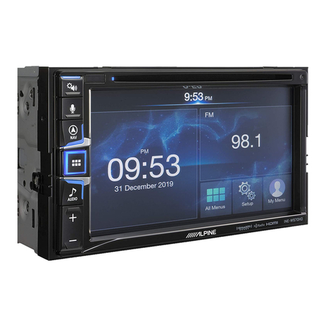
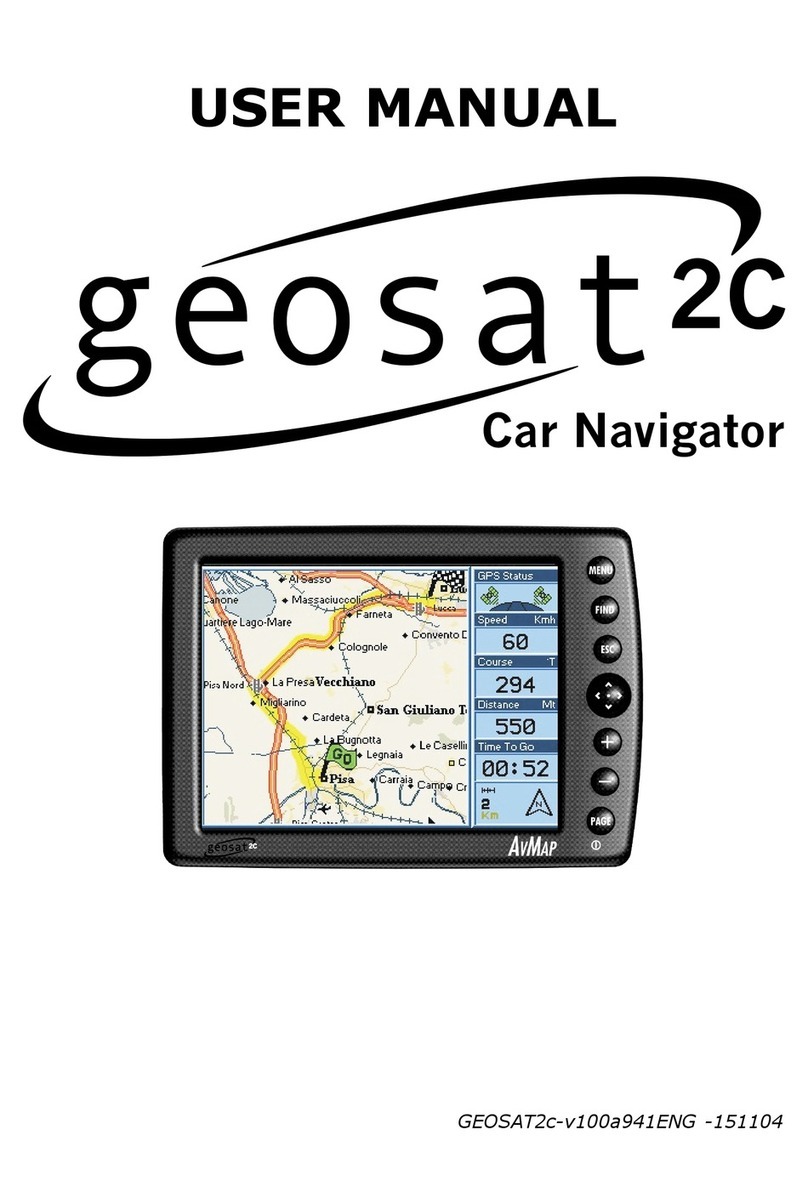
Fujitsu Ten FB678US Installation instructions

1
Subaru SD Card Navigation System
Technical Support Guide
May 2013
2013-1 Legacy / Outback

2
Technical Support Guide
Subaru SD Card Navigation System
2013-1 Legacy / Outback

3
Contents
1. Introduction of Subaru SD Card Navigation System
- Outline of Subaru SD Card Navigation System ........................
- Hard are !!!!!!!!!!!!!!!!!!!!!!...
- Screen Layout !!!!!!!!!!!!!!!..!!!!!
- Soft are !!!!!!!!!!!!!!!!!!!!!!!.
- Audio Function .!..!!!!...!!!!!!!!!!!!!...
- Navigation Function !...!!!!!!!!!!!!!!!!..
- Other Function !!!!!!!!!!!!!!!..!!!!...
2. Troubleshooting
- System Diagram !!!!!!!!!!!!!!!!!!!..
- Terminal of Navigation system !!!!!!!!!!!!!..
- Specification of Line Diagram !!!!!!!!!!.!!!...
- No po er !.!!!!!!!!!!!!!!!!!!!!!.
- No sound (All modes) !!!.!!!!!!!!!...!!!!.
- No sound (AM/FM)!!!!.!!!!...!!!!!..!!!!.
- No sound (Satellite radio) !!..!..!!!!!!!!.!!!.
- No sound (CD) !!!!!.!!!!!!!!!!...!!!!.
- No sound (USB) !!!...!!!!!!!!!!!.!!!!..
- No sound (iPod) !!!!!!!!...!!!!!!.!!!!..
- CD skip !!!!!!!!!!!!.!!!!!!..!!!!..
- CD on’t play correctly !!!!!!!!..!!!!!...!!.
- Sound is discomforting !!!!!!!!!!!!!..!!!.
- No illumination !!!!!!!!.!!!!!!!...!!!!.
- No display !!!!!!.!!!!!!!!!!!..!!!!.
- Current GPS position does not move !..!!!!!.!..!!.
- Bluetooth does not ork !!!!!!!..!!!!!!!.!.
- Rear Vie Camera on’t display !!!.!!!!!!!!!.
- Aha Radio !!!.!!!!!!!!!!!!!!!!!!!
3. Frequently Asked Questions (FAQ)
- Navigation !!!!!!!!!!!!!!!!!!!!!!.
- Bluetooth Hands-free !!!!!!!!!!!!!.!!!!.
- Audio / Visual !!!!!!!!!!!!!!!!..!!!!..
- Others !!!!!!!!!!!!!!!!!!!..!!!!..
. Glossary
- [A] - [M] !!!!!!!!!!!!!!!!!!!.!!!!.
- [N] - [S] !!!!!!!!!!!!!!!!!!!.!!!!..
- [U] - [number] !!!!!!!!!!!!!!!!..!!!!..
14
15-17
18-21
22
23
24
25
26
27
28
29
30
31
32
33
34
35
36
37-56
58-71
72-89
90-115
116-121
122
123
124
4-5
6
7
8
9-10
11
12-13
4
Head Unit and SD Card Combination
Please verify that the correct SD card is inserted in every head unit.
Outline of Subaru SD Card Navigation System
1. Introduction of Subaru SD Card Navigation System
Vehicle Country ID SUBARU No. SD Part No. Map Ver.
13MY Legacy / Outback
/ H/K Amp
USA FB678US 86271AJ67A
86283AJ67A
2011 Q3
CANADA FB778US 86271AJ77A
13MY Legacy / Outback
/ Aha Radio, / H/K Amp
USA FE688US 86271AJ68A
86283AJ68A
CANADA FE788US 86271AJ78A
14MY Legacy / Outback
/ Aha Radio, / H/K Amp
USA FE688US 86271AJ80A
86283AJ66A
2012 Q3
CANADA FE788US 86271AJ90A
14MY Legacy / Outback
/ Aha Radio
USA FE699US 86283AJ69A 86271AJ81A
Applicable Models
Product Overview
Navi media Display Voice recognition
SD (4GB) 7-inch WVGA Yes
Basic
function
Junction view Voice recognition Traffic information Motorway information
Yes Yes XM Yes
Navi
Satellite radio HD radio USB audio / video iPod control
XM *Yes Yes Yes
Audio
Steering SW Rear view camera Bluetooth Read out SMS / Email
Yes Yes (if applicable) Yes Yes
Other
SAMPLE
86283AJ67A
2011 Q3
*HD Radio service available in
USA only (as of May 2013)
SD card must be returned with any exchange unit core.
..
.

5
Summary of Features
13-14MY Legacy / Outback
AV
Display 7-inch WVGA
Deck Single CD
Satellite radio XM
iPod/iPhone control Yes
HD Radio Yes
*1
SD Picture Yes
SMS/Email read out Yes
Voice recognition Yes (English, Spanish, French)
Navi
Motor ay service information Yes
Green route search Yes
3D Junction display Yes
Traffic information Yes (XM-Traffic)
Voice recognition (VR) Yes (English, Spanish, French)
Map Web do nload Yes
Other Rear vie camera Yes (if applicable)
USB Audio/Video Yes
Aha Radio Yes
*2
*1 HD Radio service available in USA only (as of May 2013)
*2 Aha Radio is not available for 86271AJ67A and 86271AJ77A

6
Hardware
1. Introduction of Subaru SD Card Navigation System
SD memory card slot
AUDIO button
Press to display the audio
POWER button
INFO button
Press to display the
information screen.
Press: Audio Po er ON or OFF
CD slot
VOL knob
Rotate: Adjust the volume
EJECT button
Press to eject
the DISC.
TUNE/TRACK knob
Rotate to select a radio
station, track, or file.
MAP button
Press to display
the navigation screen.
DISP button
Press to display the picture
quality adjustment screen.
Preset buttons

7
Screen Layout
Audio Source
Selector
Basic Control of
Audio Function
Control of
Navigation Function
<Audio Mode>
[AUDIO]
Split Screen
<Navigation Mode>
Full Map Screen
Changing the screens can be
done by touching the icon on
the screen.
[MAP]
Full Audio Screen

8
Software
1. Introduction of Subaru SD Card Navigation System
The main functions of the system include:
(1) Audio
(2) Navigation
(3) Information
(1) Audio function
In addition to radio and CDs, the system can also play
back sources such as iPods, iPhones, USB and Bluetooth
Audio devices. (Aha Radio if equipped)
Sound quality can also be adjusted using the operation
screen.
Audio Source Selector
(2) Navigation function
Apart from the easy-to-vie screen guides, other features
offered include detailed location information displays, a va-
riety of adjustable guide maps, and simple route change
functions
Navigation Menu Button
(3) Information function
In addition to display settings, other settings such as
and allpapers are also available.

9
Audio Function
HD radio, XM, Aha
Integrated HD Radio, XM and Aha
HD Radio, XM Tuner Control XM Traffic Information
Voice Recognition
Talk back from vehicle speaker
“Voice command please”
Voice recognition button
Microphone
Change audio
source
Audio
control
Destination
search
Hands-free
dial
iPod select
songs
USB select
folder
Yes Yes Yes Yes Yes Yes
Voice
Control
function
Operate Navigation and Audio by voice commands
M is paid service and subscription is required
Aha Radio
Smartphone with Data
service is required for
Aha functions.
Aha Radio is not avail-
able for 86271AJ67A
and 86271AJ77A.
HD Radio service available in USA only
(as of May 2013)

10
Audio Function
1. Introduction of Subaru SD Card Navigation System
Max picture resolution size: 720*576 pixel
Max layers of directory: 8 layers
Max number of folders (overall): 3000
Max number of files (overall): 9999
Max data size: 8GB
Class: USB mass storage class
Movie
*Compressed video file is supported for USB only.
<Reference>
Audio Format
*Playback is dependent on the specific version of the file format.
DivX WMV MP
Yes Yes Yes
<USB flash memory>
<Read and play condition>
<Video format>
SD Picture
Max data size: 64GB
SD card class: ALL
4 slidesho effects
Automatic resizing
Setting as Opening screen
*Slide sho supports SD card only.
*Slide sho cannot be displayed hile Navi Mode is active
*Some SD Cards functions above may not be supported
based on SD Card manufacturer specifications.
<SD card>
<Features>
Format: JPEG
Max picture data size: 10MB
Max layers of directory: 8 layers
Max number of files (overall): 500
<Read and play condition>
<Limitation while driving>
The picture slide sho ill stop once start driving
and the last picture ill be displayed on the screen.
Caution:
Do not add photo data on Map SD Card. It
may damage the soft are file. Al ays use
a different SD card to store photo data.
MP3 WMA
Yes Yes

11
Navigation Function
When approaching an ex-
press ay exit or a compli-
cated intersection, the map
s itches to a 3D display.
3D Junction Display
Voice Recognition
By using the voice control system, the destination can
be set by speaking voice commands. This enables
you to use functions that are usually inaccessible
hile driving.
High ay service area in-
formation is useful for a
long drive.
Motorway
The Green route function enables the search for
routes that reduce fuel consumption and CO2
emissions.
Green Route
The function sho s the altitude of the road currently
being driven and measured by the GPS receiver.
The minimum of 4 acquired satellites is required to es-
tablish Altitude. With 3 or less acquired satellites, "- -"
may be displayed on the navigation screen.
Altitude Reading

12
Other Function
1. Introduction of Subaru SD Card Navigation System
Rear View Camera
(Option)
Appear guidance line
Reverse On
Center of vehicle
0.5m (1.6 ft) from the
edge of Vehicle
1.0m (3 ft)
2.0m (7 ft)
3.0m (10 ft)
R
Bluetooth
Function is needed
Mobile phone
Navigation
Notification screen
The feature will only work if the cell phone being used has
the following:
1. HFP (Hands Free Profile)
2. MAP (Message Access Profile)
Message screen
Message body is read out
by system
Read out SMS/Email
Received message

13
https://subaru-aus.naviextras.com/
Map Update
NAVTEQ, acquired by Nokia provides Map Update Service for SD Card Navi-
gation System. Please visit the ebsite and make sure hich map version is
currently available.
NAVTEQ Map Update Service
Map Update Support:
If you can't find the ans er to your question or for advice on the map inside
Navigation System, please contact NAVTEQ via ebsite or call NAVTEQ at
1-888-628-6277 Monday through Friday, 9am - 8pm Eastern Time. NAVTEQ
ill respond to your inquiry ithin 72 hours.

14
Navigation
Head Unit
CD
AM/FM
XM
Bluetooth
SD slot
HD Radio
*2
Aha Radio
*3
System Diagram
USB JACK
USB Audio/Video
STEERING
SW
RADIO
ANT-AMP
The connection of each
equipment is excluded.
iPod
PWR
GPS-ANT XM-ANT
NTSC
USB2.0
(If applicable)
Back
Camera
HARMAN
AUDIO
AMP
Display
*2
HD Radio service available in
USA only (as of May 2013)
MINI JACK
(AUX)
BODY ECU
UART
*4
RADIO-ANT
MIC
LVDS
*1
PWR
PWR
*1
LVDS: Low voltage differential signaling
*4
UART: Universal Asynchronous Receiver/Transmitter
2. Troubleshooting
*3
Aha Radio is not available for
86271AJ67A and 86271A-
J77A
*6
86271AJ81A only
*6
*5
*5
All systems except 86271AJ81A

15
Connections and Pins
UA
*
Connector B Connector C
Connector D Connector E Connector F Connector G
Connector A
Not in use
1
USV1
OUT
USB audio power supply (5V)
2
US1-
IN/OUT
USB audio data
3
US1+
IN/OUT
USB audio data
UGD1
GND
Ground
5
USG1
GND
Ground
Connector A (USB)
Connector B
(REAR CAMERA)
*if applicable
1
2
3
N.C.
-
No connection
6
PKB
IN
Parking brake signal (12V)
7
CA+
OUT
Back-eye camera power supply (6V)
8
V+
IN
Back-eye camera signal (NTSC)
9
10
11
12
13
1
N.C.
-
No connection
15
CGND
GND
Ground
16
V-
GND
Ground
UART
IN/OUT
UART to/from Body ECU
5
N.C.
-
No connection
Connector C
(GPS
ANTENNA)
1
ANT
IN
GPS signal
2
GND
GND
Ground
3
GND
GND
Ground

16
Connections and Pins
1
FR+
OUT
Audio signal (Front Right)
2
FL+
OUT
Audio signal (Front Left)
3
ACC
IN
ACC power supply
BU+B
IN
Back-up power supply
5
FR-
OUT
Audio signal (Front Right)
Connector D
(POWER INPUT/
SIGNAL OUTPUT)
6
FL-
OUT
Audio signal (Front Left)
7
GND
GND
Ground
8
ANT+
OUT
Antenna amplifier power supply (12V)
9
AMP+
OUT
Audio amplifier power supply (12V)
10
ILL+
IN
Illumination signal (12V)
11
RR+
OUT
Audio signal (Rear Right)
12
RL+
OUT
Audio signal (Rear Left)
13
RR-
OUT
Audio signal (Rear Right)
1
SLD2
GND
Ground
15
ILL-
IN
Illumination signal
16
RL-
OUT
Audio signal (Rear Left)
Connector E
(ST-SW, MIC etc)
1
N.C.
-
No connection
2
REV
IN
Reverse signal (12V)
3
BRIGHT
IN
No connection
MACC
OUT
Mic power supply (5V)
5
MIN+
IN
Mic signal
6
SNS2
IN
Mic detection
7
8
9
10
N.C.
-
No connection
11
AGND
GND
Ground
12
13
1
15
16
N.C.
-
No connection
17
SPD
IN
Vehicle speed signal
18
SGND
GND
Ground
19
MIN-
IN
Mic signal
20
N.C.
-
No connection
21
SW1
IN
Mic sw signal
22
SW2
IN
Mic sw signal
23
SWG
GND
Ground
2
N.C
-
No connection
25
26
27
28
N.C.
-
No connection
2. Troubleshooting

17
1
SUB-ANT-IN
IN
Radio signal (Sub)
2
SUB-ANT-GND
IN
Ground
3
MAIN-ANT-IN
IN
Radio signal (Main)
MAIN-ANT-GND
GND
Ground
5
N.C.
-
No connection
Connector F
(RADIO
ANTENNA)
Connector G
(XM ANTENNA)
XM SIG
IN
XM signal
XM ANT +B
OUT
XM Antenna +B (5V)
2
GND
GND
Ground
3
GND
GND
Ground
1
Connections and Pins

18
Specification of Line Diagram
1. Outline
Line Diagram can check the connectivity of devises, the vehicle signals, the
radio reception and rear vie camera setting.
2. How to enter Line Diagnostic mode
Procedure:
1. Turn off audio by pressing "PWR" button.
2. While pressing both buttons (a) and (b), press and hold
the button (c) for more than 3 seconds.
Press and hold the button (b) for more than 3 seconds, or turning the
ignition s itch from ACC OFF to ON position.
2-1. Enter the Diagnostic mode
2-2. Exit the diagnostic mode
(a)
(b)
(c)
Normal Mode Diagnostic Mode
2-1. Enter
Diagnostic Mode
2-2. Back to
Operation Mode
2. Troubleshooting
PWR button

19
3.
Display Layout and Explanation
If "Camera Setting" button is touched, the screen changes to “Camera Setting” mode.
3-1. Top Display Layout
Return
Camera Setting Default
Set
Return
Camera Setting Default
Set
②
①
③
⑤
⑥
④
⑦
No
Explanation
①
Main title
[White] after check
[Black] under check
② Connected Devices
③ Results of Connectivity Check
No
Explanation
⑤ Vehicle Signal
⑥ Vehicle Signal Check Results
⑦ Enter Audio Check
④ Enter Camera Setting
3-2. Enter “Camera Setting”
⑨
⑪
⑩
No
Explanation
⑧ Return to Previous Screen
⑨ Initialization of Maker Line
Adjustment
⑩ Marker Line Adjustment
⑪ Finalization of Marker Line
Adjustment
⑧
Note:
For a detailed procedure to adjust the
camera settings, refer to STIS.
Please select the Service Manual and
refer to the Navigation System under
the Entertainment Section (ET)

20
Line Diag
Audio Check
Return
MODE SEEK DOWN SEEK UP
・AM/FM :FM XXXX kHz
・Speaker Check
Speaker Check ON
Line Diag
Audio Check
Return
MODE SEEK DOWN SEEK UP
・AM/FM :FM XXXX kHz
・Speaker Check
Speaker Check ON
3-3. Enter “Audio Check”
⑬
⑭
⑮
⑰
No
Explanation
⑬ Return to Previous Screen
⑭ Selection of Radio Band (AM/FM)
⑮ Change Radio Frequency
⑯ Radio Frequency
⑰
Speaker Check
[“OFF”, Black] after check
[“ON”, R-Blue] under check
⑯
If the "Audio Check" button is touched, the screen changes to “Audio Check” mode.
Specification of Line Diagram
2. Troubleshooting
This manual suits for next models
11
Table of contents