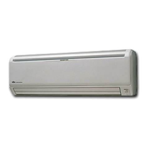
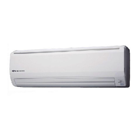
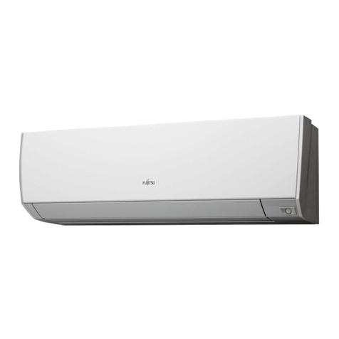
Make a TEST RUN in accordance with the installation Manual 8. 1. for the indoor unit
CHECK ITEMS8. 1. 1.
(1) INDOOR UNIT
Is operation of each button on the remote controller normal?(1)
Does each lamp light normally?(2)
Do the air ow-direction louver operate normally?(3)
Is the drain normal?(4)
Is there any abnormal noise and vibration during operation?(5)
(2) OUTDOOR UNIT
Is there any abnormal noise and vibration during operation?(1)
Will noise, wind, or drain water from the unit disturb the neighbors?(2)
Is there any gas leakage?(3)
Do not operate the air conditioner in the test running state for a long time.•
For the operation method, refer to the operating manual and perform operation check.•
Outdoor unit LEDS8. 2.
When a malfunction occurs in the outdoor unit, the LED on the circuit board lights to
indicate the error. Refer to the following table for the description of each error according to
the LED.
Error contents LED 1 LED 2 LED 3 LED 4
Communication error
(outdoor unit to indoor unit A)
●1 time - - -
Communication error
(outdoor unit to indoor unit B)
-●1 time - -
Communication error
(outdoor unit to indoor unit C)
- - ●1 time -
Communication error
(outdoor unit to indoor unit D)
- - - ●1 time
Discharge temp. sensor error ●2 times - - -
Outdoor unit Heat Ex. middle temp. sensor error
●3 times - - -
Outdoor temp. sensor error ●4 times - - -
2 way valve temp. sensor error(for Indoor unit A)
●5 times - - -
2 way valve temp. sensor error(for Indoor unit B)
-●5 times - -
2 way valve temp. sensor error(for Indoor unit C)
- - ●5 times -
2 way valve temp. sensor error(for Indoor unit D)
- - - ●5 times
3 way valve temp. sensor error(for Indoor unit A)
●6 times - - -
3 way valve temp. sensor error(for Indoor unit B)
-●6 times - -
3 way valve temp. sensor error(for Indoor unit C)
- - ●6 times -
3 way valve temp. sensor error(for Indoor unit D)
- - - ●6 times
Compressor temp. sensor error ●7 times - - -
Heat sink temp. sensor error ●8 times - - -
High pressure switch 1 error ●9 times - - -
High pressure switch 2 error ●10 times - - -
Indoor unit capacity error ●11 times - - -
Trip detection ●12 times - - -
Compressor rotor position detection error ●13 times - - -
Error contents LED 1 LED 2 LED 3 LED 4
Trip terminal L error ●14 times - - -
Outdoor unit fan motor error ●15 times - - -
Outdoor unit PCB microcomputer
communication error ●17 times - - -
Discharge temperature error ●18 times - - -
Compressor temperatuer error ●19 times - - -
4 way valve error ●20 times - - -
Outdoor unit PCB model information error ●21times - - -
Active lter error, PFC circuit error ●22 times - - -
● : ashing - : Off
LED is on a reverse
side of the board.
Hole
LED4
LED3
LED2
LED1
PUMP DOWN9.
PUMP DOWN OPERATION
To avoid discharging refrigerant into the atmosphere at the time of relocation or disposal,
recover refrigerant by doing the cooling operation or forced cooling operation according to
the following procedure. (When the cooling operation cannot start in winter, and so on, start
the forced cooling operation.)
Do the air purging of the charge hose by connecting the charging hose of gauge(1)
manifold to the charging port of 3 way valve (At lease one unit of connected units) and
opening the low pressure valve slightly.
Close the valve stem of 2 way valve (All connected units) completely.(2)
Start the cooling operation or following forced cooling operation. (All connected units) (3)
When using the remote controller Press the TEST RUN button after starting the cooling
operation by the remote controller. The operation indicator lamp and timer indicator
lamp will begin to ash simultaneously during test run. When using the MANUAL AUTO
button of the indoor unit (The remote controller is lost, and so on.) Keep on pressing
the MANUAL AUTO button of the indoor unit for more than 10 seconds. (The forced
cooling operation cannot start if the MANUAL AUTO button is not kept on pressing for
more than 10 seconds.)
Close the valve stem of 3 way valve (All connected units) when the reading on the (4)
compound pressure gauge becomes 0.05~0 Mpa (0.5~0 kg/cm2).
Stop the operation. (All connected units) Press the START/STOP button of the remote (5)
controller to stop the operation. Press the MANUAL AUTO button when stopping the
operation from indoor unit side. (It is not necessary to press on keeping for more than
10 seconds.)
