DELIVERY SET
Operation Instruction for the user and the qualified installer
5
INTRODUCTION
This user's manual includes technical
description operation, installation
and mounting guidelines, technical
data for the heat recovery ventilator
VT-501.
USE
The ventilator is designed to arrange
permanent controllable air exchange
in apartments, villas, hotels, cafes
and other domestic and public
buildings.The ventilator is equipped
with a ceramic heat exchanger that
enables supply of fresh air and
extract air with heat energy recovery
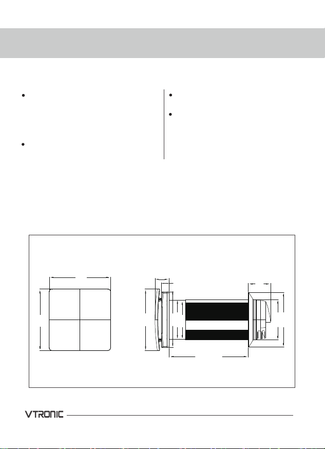
The ventilator is designed for
through-the-wall mounting. The
telescopic ventilator design enables
its installation in the walls from 250
mm to 400mm thickness for the
ventilator VT-501.
The ventilator is rated for continuous
operation always connected to
power mains.
Transported air must not contain any
flammable or explosive mixtures,
evaporation of chemicals, coarse
dust, soot and oil particles, sticky
substances, fibrous materials,
pathogens or any other harmful
substances.
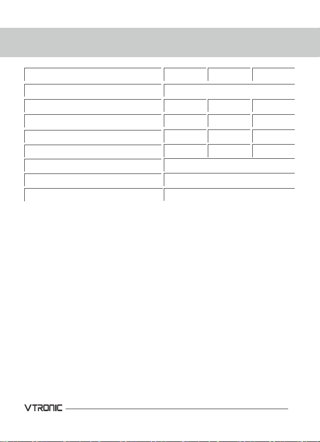
Ventilator 1 item
Fastening set 1 item
Remote controller 1 item
User's manual 1 item
Packing box 1 item
THE VENTILATION NOT INTENDED TO
BE USED BY CHILDRER PHYSICALLY
OR MENTALLY DISABLED PERSONS,
PERSONS WITH SENSORY DISORDER,
PERSONS WITH NO APPROPRIATE
QUAUFICATIOH.
INSTALLATION AND CONNECTION
OPERATIONS MUST BE PERFORMED
ONLY BY PROPERLY QUALIFIED
PERSONNEL AFTER THE APPROPRIATE
SAFETY BRIEFING.THE VENTILATOR
INSTALLATION SITES MUST PREVENT
ACCESS BY UNATTENDED CHILDREN.