Fukuda Denshi FC101 User manual

Rotary Laser
Service Manual

2
Content
1.0 Instruments & Accessories。。。。。。。。。。。。。。。。。。。。。。。。。。。。。。。。。。。。。。。。(3)
1.1 Operations。。。。。。。。。。。。。。。。。。。。。。。。。。。。。。。。。。。。。。。。。。。。。。。。。。(3)…
1.2 Key functions。。。。。。。。。。。。。。。。。。。。。。。。。。。。。。。。。。。。。。。。。。。。。。。(4)
2.0 Structure 。。。。。。。。。。。。。。。。。。。。。。。。。。。。。。。。。。。。。。。。。。。。。。。。。
。。(6)
2.1Housing set。。。。。。。。。。。。。。。。。。。。。。。。。。。。。。。。。。。。。。。。。。。。。。。。。。。(7)
2.2Underpan set。。。。。。。。。。。。。。。。。。。。。。。。。。。。。。。。。。。。。
。。。。。。。。。。。。(8)
2.3Pendulum。。。。。。。。。。。。。。。。。。。。。。。。。。。。。。。。。。。。。。。。。。。。。。。。。。。(10)
2.4PCB。。。。。。。。。。。。。。。。。。。。。。。。。。。。
。。。。。。。。。。。。。。。。。。。。。。。。。。。。(13)
2.5 Instrument Assembling 。。。。。。。。。。。。。。。。。。。。。。。。。。。。。。。。。。。。。。。(14)
3.0 Instrument Inspect 。。。。。。。。。。。。。。。。。。。。。。。
。。。。。。。。。。。。。。。。。。。(15)
3.1 Instrument level adjusting。。。。。。。。。。。。。。。。。。。。。。。。。。。。。。。。。。。。。。(15)
4.0 Horizontal-line Adjustment。。。。。。。。。。。。。。。。。。。。。。。。。。。。。。。。。。
。。。。(17)
4.1 Inspection 。。。。。。。。。。。。。。。。。。。。。。。。。。。。。。。。。。。。。。。。。。。。。。。。。(17)
4.2 Adjustment。。。。。。。。。。。。。。。。。。。。。。。。。。。。。。。。。。。。。。
。。。。。。。。。。。。(17)
5.0 Detector 。。。。。。。。。。。。。。。。。。。。。。。。。。。。。。。。。。。。。。。。。。。。。。。。。。。。(17
6.0 Malfunctions & Eliminations。。。。。。。。。。。。。。。。。。。。。。。。。。。。
。。。。。。。。(19)

3
1.0Instrument and accessory
The whole set include Main body, detector FRD100,clamp,remote control and
charger FC101.It can assemble 4pcs rechargeable battery ,only have to loose the
screw on the base. And take the battery off.
1.1 Basic function:
1. Press the ON/OFF, it has a rotary laser beam form a horizontal
Main boday Remote control
FRD100detector and clamp
FC101charger

4
surface, and a plumb upward laser and a down point, it has a vertical
surface and horizontal beam.
2. It can speed adjusting, stop rotating, move left or right step
by step, or directional scanning and slope setting.
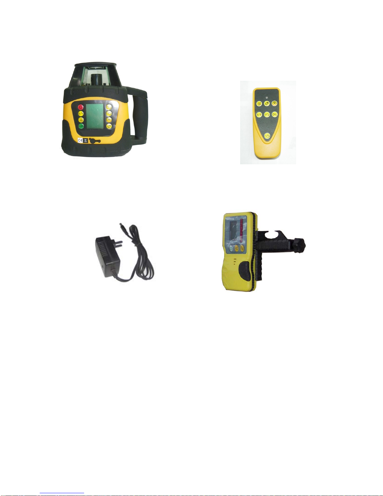
3. It can match with detector FRD100, and get the position of laser
beam from the indict line of the detector.
1.2 Panel function and utility
(1)ON/OFF/Manual: Control the state of ON/OFF, it will have display on
LCD about leveling and the power, press 3 seconds enter onto Manual
function; there will be a hand icon.
(2)Speed up: recyclable, it will display the on LED. It has 5 steps: 0
-60-120-300-600 r.p.m
(3)Direction scanning: recyclable, the angle will be display on LED,5
steps from 0-10°-45°-90°-180°
(4)Slope setting: Can switch the laser unit between manual mode and
self-leveling mode. There is a triangle icon on LED.
(5)+/left spining: It adjusts the slope when in slope setting mode and
it will be display on the LED. It can control the laser head move
anti-clockwise step by step when laser head is stopping or direction
scanning in self-leveling mode.
(6)-/right spinning: It adjust the slope when in slope setting mode, and
also display on the LED. It can control the laser head move clockwise
step by step when laser head is stopping or direction scanning in
self-leveling mode.

5
(7) X/Y switch key: When the instrument is under slope setting mode,
it can switch between X axis or Y axis to set the slope.
(8)Tilt mode: When the instrument is set in Tilt mode when it leveling,
any movement or shock, it out of leveling, and indicate user the
statement is changed, it has TILT display on LED.
2.0 Structure
FRE207-2-1001Housing set
FRE207-2-200 base set
FRE207-100Pendulum set

6
2.1Housing set
NO. CODE NAME Quantity
1 FRE207-109 Top cover 1
2 FRE207-106 window glass 1
3 FRE207-110 Top rubber cover 1
4 FRE206-003 connecting board 1
14 FRE206-001 lamina Lucida 1
15 LED 1
16 GB/T845-1985 screwST2.2×4.5 4
5 Menu sticker 1
6 FRE101-302 Shielding glass 1 1
7 FRE203-214 Gasket ring 1
Housing bombing illustration
1
2
3
4
7
5
8
11
9
10
6
12
13
15
16
14

7
8 FRE203-109 1
GB/T845-1985 Screw ST2.2×9.8 4 9
GB/T 96-1985 φ2.5 gasket 4
infrared receiving
terminal 4 10
FRE101-315YB Receiver board 1
12 FRE206-002 Middle Housing 1
13 FRE203-206 Bottom rubber cover 1
11 GB/T845-1985 Screw ST2.2×4.5 4
2.2 Housing set
Speed up
-/left spinning
Direction scanning
+/right spinning
X/Switch
ON/OFF/Manual
Illustration of Menu function
Tilt
Slope setting

8
2.3Underpan set
NO. CODE NAME Quantity
1 FRE207-302 PCB 1
2 FRE203-205 Handle 1
3 FRE207-111 Handle cover 1
4 FRE207-108a Base 1
5 FRE203L-308 Press board 1
6 FRE203-204 Battery cover 1
7 FRE203-208 battery fixing
frame 2
8 FRE203L-312 socket cover 1
9 FRE203N-007 battery seal ring 1
10 FRE203N-008 battery seal ring II 1
11 FRE203L-306 tight nut 1
12 FRE207-117 Bubble base 1
Bombing illustration of Underpan set
1
2
3
4
5
6
10
8
7
11
9
12

9
2.4 Pendulum set
NO. CODE NAME Quantity
FRE101-307 pentagonal prism
10×10
1
FRE102-410 optical wedge
fixing base 1
FRE102-411 optical wedge base 1
1
FRE102-412 optical wedge 1
Pendulum set bombing illustration
1
4
5
2
3
8
9
10
6
7
11
13
14
15
16
17
12

10
FRE207-104 prism base 1
FRE203I-205 prism cover 1
2 FRE101-112 raster 1
FRE101-107 scanning gear II 1
3 FRE203I-207 scanning base 1
6801ZZ bearing 2
FRE101-110 gasket I 1
FRE101-108 Nut 1
4
FRE101-124 stop collar 1
FRE101-106 scanning gear 1 1
FRE202-116a motor fixing board
Scanning motor 1
GB/T818-2000 Screw M1.6×4 2
5
GB/T818-2000 Screw M3×6 2
FRE207-105 Pin base 2
GB309-85 φ3×21.8 Pin 2
PCB opto-coupler
(scanning)
2
GB/T818-2000 Screw M3×6 2
GB/T80-2000 Screw M3×10 8
6
GB//T96-1985 φ3 gasket 2
FRE203-105 Universal holder 1
GB/T70.1-2000 Screw M3×15 4
7
GB/T80-2000 Screw M2.5×3 2
FRE207-104 leveling frame 1
8 GB/T818-2000 Screw M2×8 4
9 FLE441-107 Pin 2
10 FRE207-103 Fixing board 1
11 FRE203-211 Alarm base 1
P7-106 Alarm spring 1
11 GB/T818-2000 Screw M2.5×6 2
FRE203-106 Universal ring 1
FLE441-107 Pin 2
GB/T80-2000 Screw M2.5×3 2
12
623ZZbearing 2
FRE203-108 Pole 1
P6-1-308 Spring 2
GB/T70.1-2000 Screw M3×8 1
13
GB//T96-1985 φ3 gasket 1
Leveling motor 2
FRE207-201 Screw 2
FRE207-202 fixing frame 2
FRE207-203 plunger ring 2
FRE207-204 traveling block 2
14
FRE207-205 Gasket ring 4

11
FRE207-206 gear 4
GB309-85 φ3×15.8 Pin 4
15 623ZZ bearing 2
FRE203-103 Pendulum 1
6512 diode(upward) 1
16 1526 diode
(downward) 1
Bubble base set 1
17 GB/T80-2000 screw M3×8 6
2.5 Main PCB
X motor socket Y motor socket
Direction
scanning
socket
Alarm socket
scanning
motor
socket
Upper laser
socket
Down dot socket
Power socket
Charger
soc
k
et
Sensor socket
Keyboard
socket
Infrared receiver socket

12
2.6 Assembling
Housing set
Pendulum set
Base set

13
3.0 Instrument Inspect
(1)Place the instrument at the point of 50m in front of wall,(set a
scaleplate at the point of 50m away from the instrument), Then adjust
the level of the base approximately to aim the X1 to the wall(or
scaleplate)as depicted below:
(2)Switch on the power, then measure the h1 of X1-beam on the wall or
scaleplate by using detector.
(3)Loose the screw of the tripod, then turn around the instrument 180o
to measure the h2 of X2-beam on the wall or scaleplate. D-value between
h1 and h2 ought to be less than 10mm (4)Inspect the Y-beam with the same
way.
Assembling bombing illustration
X1-beam
X2-beam
X1
Approx.50m
h1
h2

14
3.1 Level calibration
1. If the difference of H1 and H2 is within 5mm-10mm,we may adjust
accuracy as following:
(1) Press ON/OFF,the indicator light on,it enter into self-leveling.
(2) Press G 3 seconds, X will twist on the LED, it enter into X direction
accuracy adjustment.
(3) Press +/-,laser beam will move step by step, check the laser beam
at Tilt mode, till the difference of H1 and H2 within 5mm,and press
G 3 seconds, the Tilt icon is disappear on the LED, the adjustment
is recorded.
(4) Press G 3 seconds, X is twist on the LED,then,press the X/Y switch
key is twist, it enters into Y direction adjustment.
(5) Press +/-,laser beam will move step by step, check the laser beam
at Tilt mode, till the difference of H1 and H2 within 5mm,and press
G 3 seconds, the Tilt icon is disappear on the LED, the adjustment
is recorded.

15
2. When the difference of H1 and H2 is beyond 10mm, it need adjusting
mechanic, as following:
As the above picture, just X1 or X2 (Y1 or Y2) under
Self-leveling statement, till the difference is within 5mm.
Attention: If the calibration is out of range, You should better
contact distributor for repairing.
X1
Y2
X2
Y1
B
A
C
D

16
4.0 Horizontal-line Adjust
4.1 Inspection
(1) Place the instrument between two walls with the distance of 30m
(or two scaleplates with the distance of 30m)
(2) Place the instrument according to horizontal setting manner and then
adjust the instrument.
(3)Switch on the power, and then measure the middle point of the laser
beam on two walls(or scaleplates),There are hA、hB and hA’、hB’
(4) △1=hA-hA′, △2=hB-hB′
D-value between △1 and △2 ought to be less than 4mm.
4.2 Adjusting(Vertical)
If D-value between Δ 1and Δ 2 is more than 4mm , adjust the
instrument in the same way of level adjusting. Please refer to the details
of Y-axis calibration in 3.0 and 3.1.
hA hB
0.5m Approx. 30m 0.5m
Approx.30m
hBhA

17
Rough orientation indicator
Upward bias
Downward bias
Rough orientation
Accurate orientation
Buzzer(off)Low power High power Buzzer()
精对准状态
Accurate orientation indicator
5.0 Detector
5.1 FRD100: Introduce of the detector’s circuit.
1. The laser beam is received by silicon photocell. After amplifying
and judging the signal received, the detector will send out command signal
to control the display of LCD and the buzzer.
States of buzzer : upward bias alarm 、 downward bias alarm 、
accurate-orientated alarm(prolonged sound)
2.Normal fault and repair
(1)Buzzer doesn’t work
① Symptons:Buzzer off when press key.
LCD illustration

18
② Reason for causing this problem: a. Socket of buzzer dropt。b. Broken
of circuit board。
③ Repair: a. Open the cover then insert the socket.
b. Broken of circuit,send back to manufacturer.
(2)No response when power on.
①Symptoms:Press ON/OFF, there is no sound, no display on LCD.
② Reason: a. Wrong set of batteries. Socket on PCB has dropt. c.
Fault of circuit board.
③ Resolve method:
a. Open the batteries cover, then reset the batteries.
b. Open the shell, then insert the socket
c. Fault of circuit board,send back to manufacturer.
6.0 Malfunctions & Eliminations
6.1 Failures in starting up
(1) Symptoms:
After pressing the Key ON/OFF, power indicator can’t light and also
the instrument doesn’t start up.
(2) Causes:
a. Poor contact of keys on the panel or panel plug.
b. Poor contact of batteries or power plug, and insufficient power,
c. Troubles of PCB.
(3) Eliminations:
a. Take off the shell,and renew the panel or connect the power plug with
PCB well.

19
b. Take down the cover of battery case to check whether t here are some
dirt or rust between the spring and spring strip,and clear off them
if it is
true;Recharge the batteries till power is sufficient and then
detach the shell to connect the power plug with PCB well.
c. Detach the shell to change the PCB.
d. Please contact the supplier when the instrument still doesn’t start
up after all your effort above.
6.2 No spinning of laser head.
(1) Symptoms:
The laser beam is being emitted but the laser head doesn’t rotate after
instrument is power on.
(2) Causes:
a. Center to center distance of gear is not suitable,gearing is abnormal.
b. Troubles of scanning motor.
c. Laser head has touched the optical coupler.
d. Troubles of PCB.
(3) Eliminations:
a. Take off the shell to readjust the center-to-center distance of the
gear.
b. Change the scanning motor after taking off the shell.
c. Detach the shell to readjust the space between laser head and optical
coupler.
d. Change the PCB.

20
This manual suits for next models
1
Table of contents
Other Fukuda Denshi Measuring Instrument manuals