Safety Warning:
Looking for financing or eager to buy, contact Sales:
Need help, visit us at our Help Center or contact Support:
Do not leave your machine unattended.
Avoid using materials made of carbon or that contain carbon
components.
Have a fume extractor ready to catch any fumes or vapors
that may be created during the welding process
Do not store the laser machine or its accessories near eye
level. Never stare directly into the laser when running a
project. Always wear the provided safety goggles.
Do not run your machine is any cables or connection are
loose or damaged in any way.
Inspect your machine before each use. Do not use if the
machine or its accessories are damaged in any way.
Always maintain a clean work area.
1
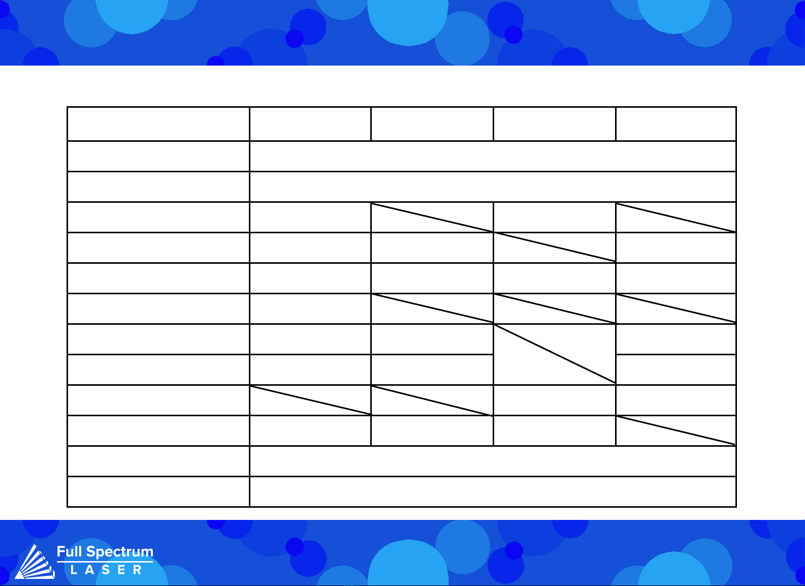
Specications:
Test Conditions
(if applicable)
Minimum Average Maximum
Operating Voltage 200V AC 220V AC 240V AC
Input Power 100 % Output 4.5 KW
Operating Ambient
Temperature
10 ℃40 ℃
Operating Ambient
Relative Humidity
10 % 85 %
Laser Cooling
Method
Air Cooled
Tip Cooling Method Nitrogen and Argon gas cooled
Storage Temperature -10 ℃60 ℃
Dimensions 667 X 276 X 542 mm
Weight < 38 kg