Fullwell WDM PON EDFA User manual

The User Guide
16 PONS de 22 dBm
WDM PON EDFA

2
Content
1 Overview.......................................................................................................................................... 3
2 Product structure diagram................................................................................................................ 4
3 The main working parameters..........................................................................................................5
4 Operation instruction........................................................................................................................6
5 Network management applicatons...................................................................................................8
6 The notes about optical connection..................................................................................................9
7 Other notes..................................................................................................................................... 10
8 The scope of the product warranty………………………………………………………………10

1 Overview
1.1 overview
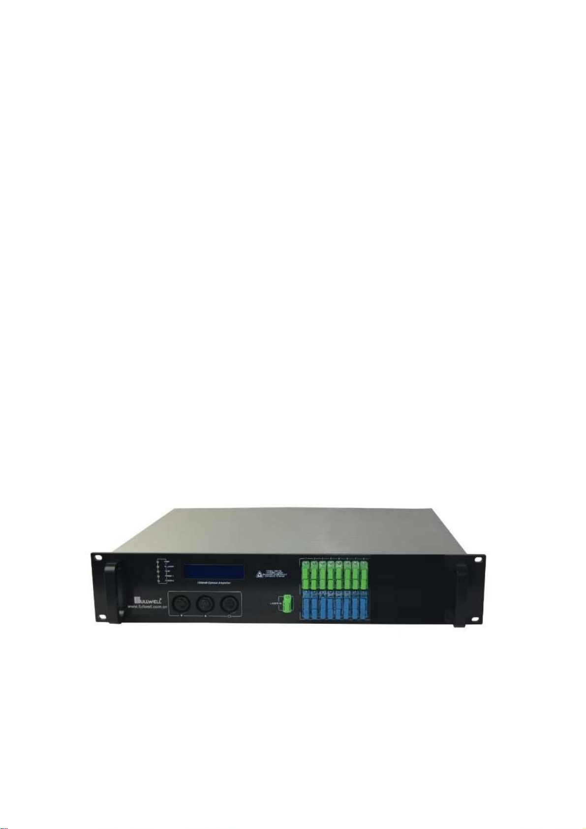
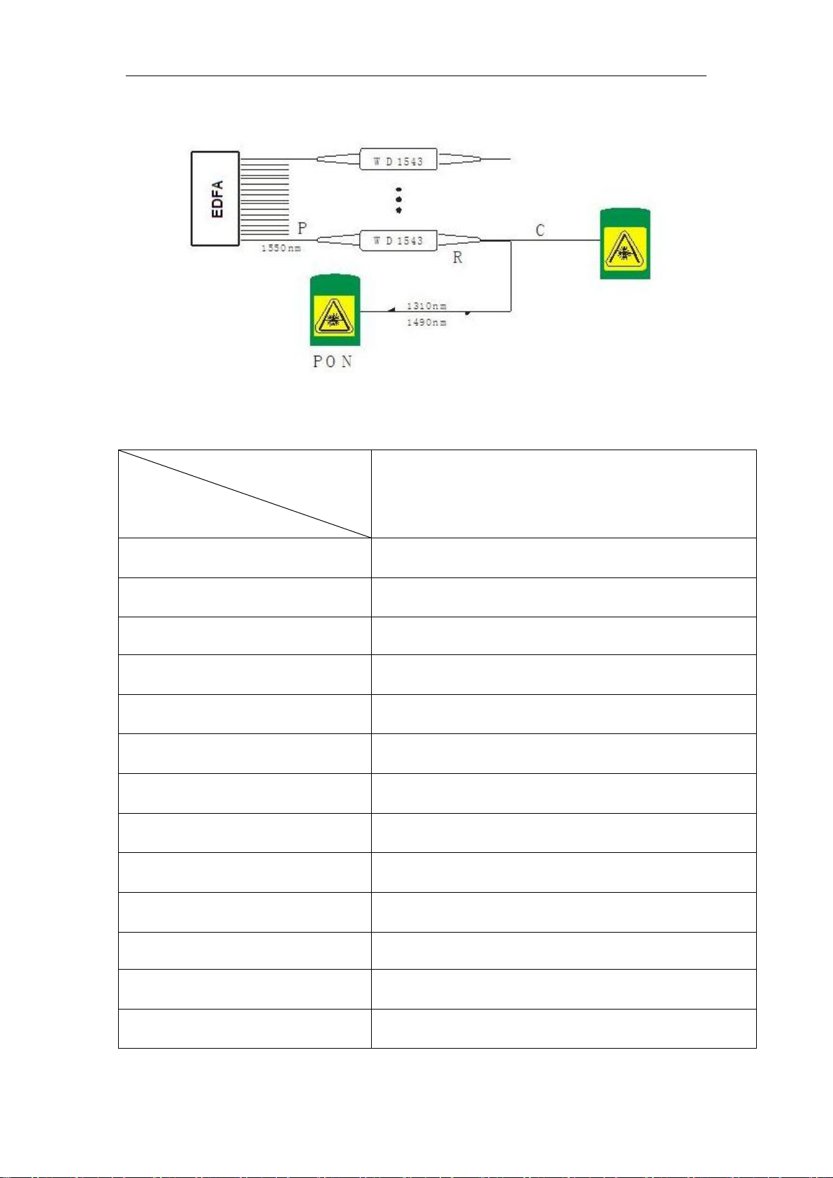
EDFA 16 pons Series WDM EDFA Combiner, High power Erbium Doped Fiber Amplifier, it is the core
equipment of three of one net in optical transmitter system, input 8 ports PON+1port CATV and output
8 ports combined 1550/1490/1310nm. The combined optical output power: 15dBm. plug-in dual power
supply, achieved the function of OLT and CATV 1550nm optical single combined and amplify, having
high cost performance value.(Erbium Doped Fiber Amplifier)is a representative one in the optical
amplifier.As the EDFA’s wavelength is 1550nm, it is in line with the low-loss band of fiber and its
technology has been relatively mature, so widely used. Erbium-doped fiber is the core components of the
EDFA, it makes quartz optical fiber as matrix material, and incorporate a certain proportion of rare earth
element erbium ions(Er3 +)in the core of a fiber.When certain amount of pump light is injected into the
erbium-doped fiber, Er3 + have been excited from the low-energy level to the high energy level, due to
Er3 + has a very short lifespan on the high energy level, and soon transit to a higher level by the form of
a non-radiative, and form the population inversion distribution between this energy level and
low-energy-level. Because the energy between these two energy levels is exactly equal to the photon
energy of 1550nm, stimulated emission of 1550nm light can only occur, we can only enlarge 1550nm
optical signal.
EDFA 16 PONS Series WDM EDFA Combiner , adopt 980nm or 1480nm high linearity, optical
isolation, the DFB, thermoelectric cooling DFB laser produced by JDSU, Fujitsu, Nortel, Lucent, Fitel
and other world-renowned semiconductor companies as the pumping source. In the interior of the
machine is equipped with the light power export stable circuit and laser thermoelectric cooling device
Temperature stability control circuit to ensure optimal machine performance and long-life laser
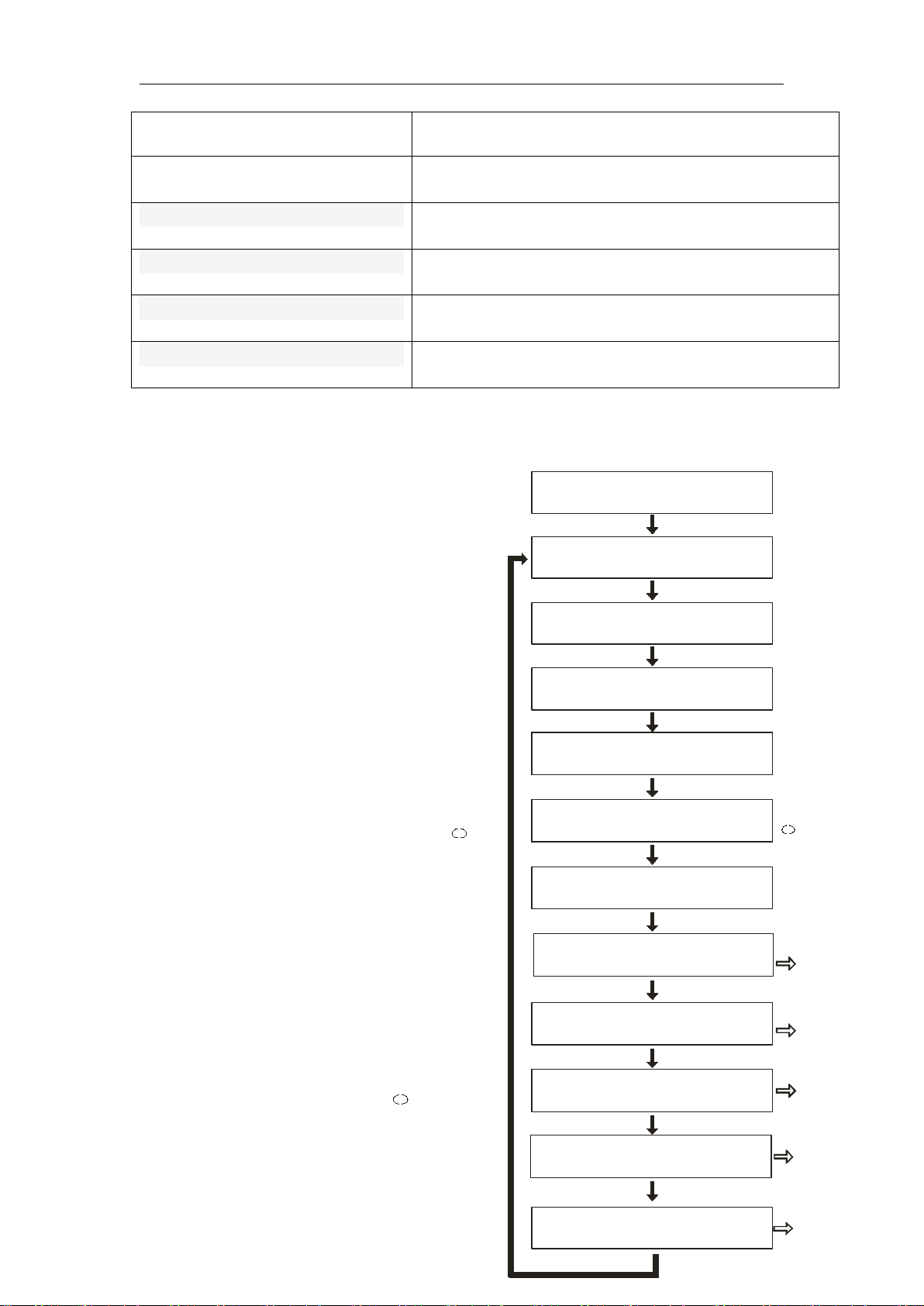
stability.The microprocessor software monitor the lasers’working state, the Digital Panel(VFD)displays
the operating parameters.Once the laser operating parameters deviate from the permissible range set by
the software, micro-processing will automatically turn off laser power, red light goes on to warn, digital
panel prompts cause of troubles., a detailed report of the device parameters please read"instructions.
1.2 Features
1.2.1) High quality: adopt multimode large power pump laser, power is optimized reasonably by
software, and can most unlimited reduce NF of EDFA, it is comparable with EDFA. The feature can
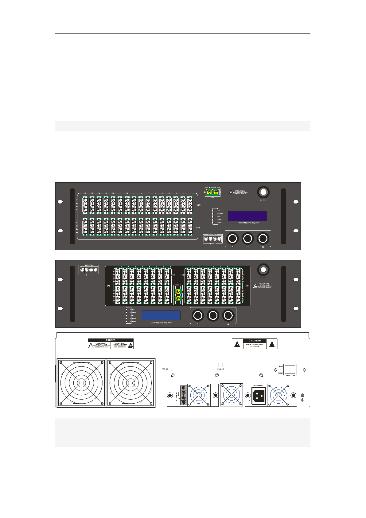
make system achieve excellent CNR. 1.2.2) Reliability: The 19 "2U rack, built-in high-performance
plug-in dual power supply, it can work at 85 ∽ 265Vac City Network Voltage, As well as an optional
DC48V power supply (reservations required);chassis cooling can be automatic control by temperature.
1.2.3) Intuition: The pump laser is the most expensive machine components, machine equipped with
microprocessor monitors the working state of the laser, the panel LCD window displays the operating
parameters. 1.2.4) Network type: Select All-piece status monitoring transponder guarantees to meet the

4
national standard and be compatible with the SCTE HMS standard, it enables network
management to monitor capabilities.
1.2.5) The plug is draw-out type: switching power supply is draw-out type with aluminum profile
structure, it helps greatly to cooling and replacement. Besides it can make dual supply cold-heat
backup.
1.2.6) Adjustable output optical power: You can adjust the range of output optical power
(downwards -3dB), it is required specification when user orders.
1.2.7) High output power: Matched output power maximum is 4W∽6W.
1.2.8) Some models can be integrated WDM, in GPON, EPON is more simple to use
2 Product structure diagram
2.1 EDFA front panel, back panel diagram
1
2
SYS.NORMAL V6.40 0
HTTP://WWW.
SYS.NORMAL V6.40 0
HTTP://WWW.
2.2 The block diagram of the integrated WDM

5
3 Modules main technical indexes
Model
Item
Operating wavelength (nM)
1545~1555
Input optical power(dBm)
-10~+10
Nominal input optical power (dBm)
+3
Noise figure (dB) (+3 dBm,@1550nM)
5.0~6.0
Gain flatness(dB)
<±0.3
Stability of output optical power (dB)
<±0.5
Polarization sensitivity (dB)
<0.2
Polarization modal dispersion (ps)
<0.5
Optical connector(IN/OUT)
SC/APC, SC/PC
Pump work quantity (N)
4
Saturated output power (dBm)
18dBm (According order demands.)
Power supplies (Vac)
115~265(draw-out plug)
Power supplies (Vdc)
48(draw-out plug)-optional

6
Operating temperature (℃)
0~50
Size (mm)
88×482.6×387
WDM-PON with optical path
PON port operating wavelength (nm)
1310/1490
PON port insertion loss (dB)
<1
1550 port insertion loss (dB)
<0.5
4 Operation instructions
4.0) Boot show: Please put the plug in the outlet
with AC220V, and the LCD panel will show
“SYS_INITIALIZATTING Wait……” , after system
initialization, the LCD panel will show as Figure (1)
in page “0”. The LCD panel shows “SYS.NORMAL
V6.00”.
4.1) Product Type: Figure (2) in page “1.1”.
4.2) Product serial number: Figure (1) page "2"
4.3) Optical power input: Figure (1) page"5".
Displaying the current optical power input. When the
optical power output is less than -10 dBm, it displays
" IN OPTICAL POWER <-99 dBm".
4.4) Query output optical power: Figure (1)
page "6". In the current page click the button " " to
query A. B, C, D the four parameters of optical power.
As shown in Figure (2).
4.4.1) Device temperature: 4.1, 4.2, 4.3, 4.4
display the A&B, C&D route the actual optical power
(referential ration) of single export in the front panel,
by “6.1” and “6.3”,and it also can be pulled down
3dB. When the optical power output is less than -10
dBm or the route is out of existence, it displays
"------"
4.5) Device temperature: Figure (1) page "5". In
the current page click the button " " to ensure
device temperature and setting state of fans. 45
degree.
4.5.1) Temperature of motherboard and
SYS .INIT IALI Z ATIO N
WAI T... ...
SYS. NORMA L V6. 0 0 0
HTT P//WW W.
MOD EL 1
FWA -1550 H
S/N 2
NJJ-100425
+1.8dBm
MM PU MP PATH 7
PUM P PARAM ETE R 8
Se l ect→
POW ER PARA METE R 9
Sel ect→
NET WORK CO NFING . A
Se l ect→
+1.8dBm
AUT O
3 3. 5℃
IN OP TICAL P OWE R 5
FAN S TATUS 4
CAR .T EMP ERATUR E 3
OUT O PTICA L POW ER 6
Set← →
Se l ect→
Se l ect→

7
pump housing: Figure (3) page "1" and page "3".
4.5.2) fan status: Figure (1) page"4" . The fan, a total of three kinds of working state can be
adopted .In the current page, click the" "key to change the working state, while in the "AUTO"
state, when the device internal temperature is higher
than 35 ℃, the SCM will automatically open the
chassis fan to cool, and it will not close until the
temperature dropped to 30 ℃.
4.6) query the parameters of pump laser:
Figure (1) page "6". In the current page click the
button " " to query the parameters of pump laser.
As shown in Figure (2).
4.6.1) Pump laser bias: laser 1, 2, 3
bias, 6.1,6.2,6.3 in Figure (4), shows the
bias current of the LD within the current
laser. when the operating current is greater
than 130% of rated current, the working
life of laser are affected, even damage the
lasers. Therefore, when detected laser
operating current is greater than 130% of
rated current. The internal hardware
circuit of equipment has limited its scope. When the bias current directives is "----", it states that
the pump laser was not be used. Temperature and cooling current show similarly.
4.8.2) Laser Temperature: lasers work properly at 20 ℃∽35 ℃temperature range. 6.4
in Figure (4). LCD displays the actual temperature of laser, such as
"25.5 ℃", when the detected temperature is 20 ℃~ 30 ℃, the LCD
displays real-time temperature.
4.8.3) laser
cooling current:
6.5 in Figure (4): In
order to ensure the
internal temperature
of laser range from
20 ℃to 30 ℃, we
should provide
Thermoelectric
cooling device a
certain amount of
operating current.
OU T OP . POW ER C 4 .3
16 .5 dBm
O U T OP . POW ER D 4.4
1 6 .2 dBm
图(2 )
R etu rn Fr on t men u 4.5
Sel ec t←
OU T OP . POW ER B 4 .2
16 .6 dBm
OU T OP . POW ER A 4 .1
16 .3 dBm
PU MP B OX T E MP . 5 .3
30 .2℃
PU MP B OX F A N 5 .4
AU TO
图(3 )
Re tu rn Fr on t men u 5 .5
Sel ec t←
MO TH ERB OA RD FA N 5 .2
AO TO
MO TH ERB OA RD TE MP . 5.1
35 .6℃
Se l ect←→
Se l ect←→
PU MP _3 BI AS C UR. 6 .3
+3 52 mA
P U MP _3 TE MP ER. 6.4
2 5 .3℃
图(4 )
R etu rn Fr on t men u 6.6
Sel ec t←
PU MP _2 BI AS C UR. 6 .2
20 30 mA
PU MP _1 BI AS C UR. 6 .1
18 42 mA
P U MP _3 RE F. CUR . 6.5
+ 0 21 9mA
+12V P OWE R 7. 3
+24V P OWE R 7 .4
+12.2V
Retu rn Fr on t Men u 7.5
Se le ct←
+2 4. 5V
图(5 )
+5V PO WER 7. 1
-5V PO WER 7. 2
+5.0 V
-5 .0 V

8
When the detected working current of thermoelectric cooling device is within-1500mA ~ +1500
mA, the LCD displays real-time current. When the current is positive, the TEC cool.
4.7) Power parameter query: Figure (1) page"8".In the current page click the button " " to
query the power parameters, as shown in Figure (3). the display circuit of supply voltage (+5
V,-5V): displays real-time values of ± 5V power supply.
4.9) setting IP address: Figure (1) page "9". In the current page click the button " " to
search and configuration net (if you didn’t purchase the network transponders, you can skip this
step)
In the LAN, this machine should be assigned an IP address and related information. Click
" " to enter "NETWORK CONFING. 9", then click " " to enter the program flowcharts as
shown in Figure (4) The Flowchart shown in pages 9.1.
4.9.1) setting IP address: Press key " " to
enter the first in paragraph 1 of IP address, click
" " the number increases, click " " number
decreases,after the number is selected
well ,press " " key to enter the second setting,
and so on. If there is only one paragraph, the
front figures are 0.
4.9.2) mask: Click " " to enter the following
sequence flow chart on page A.2, general
equipment has been set "255.255.255.000" in
the factory,so adjustment is unnecessary.
4.9.3) Default Gateway: Setting method
ibid.
4.9.4) the preferred DNS settings:
Setting method ibid.
4.9.5) alternate DNS settings: Setting
method ibid.
5 Network management applications
HFC network management system, has always been a difficulty that concerned by users and
manufacturers. Imported equipment is generally claimed with a network management system
which is based on industry standard RS232 or RJ45 interface. In order to achieve the network
management, the users need to purchase high-cost private network management software. And
each manufacturer's software is not compatible with each other. To achieve network management
is very difficult. At present there are no news reports about available network management in
Domestic system. If adopt the SNMP, the users also need to purchase specialized network
management software and there are incompatible issues between manufacturers. Many domestic
manufacturers also claim that their equipments have a network management system or are
compatible with the AM company network management system. but the device's RJ45 or RS232
interface is basically vacant and cannot achieve the network management functions.
Our company is the well-known manufacturers in the cable broadband optical transmission
system. We have been concerned about how to use the most economical and most convenient way
IP ADD RES S 8 .1
SU BN ET 8 .2 AD D RE SS
GA TE WAY 8 .3 A DD RES S
AG EN T_ TR AP I P(1 ) 8 .4
AG EN T_ TR AP I P(2 ) 8 .5
19 2. 168 .0 18. 012
25 5. 255 .2 55. 000
19 2. 168 .0 18. 001
19 2. 168 .0 00. 144
19 2. 168 .0 00. 144
Re tu r n Fr on t Men u 8.6
Se le ct←
图(6 )

9
to achieve the network management in the cable broadband networks. Now the ESV6.0 network
management system launched by our company is a new network management concepts based on
the SNMP / TCP / IP protocol.
5.1) Interface of integrated work of the monitor server
After plugging the optional transponder, the machine has the function of network management,
just need to connect the RJ45 interface signals to the LAN, and connect to the main server from
any of the LAN Ethernet port., then set up IP addresses, according to the method in 4.A etc. so we
can monitor the machine’s running conditions at real time when the network management system
is running.
5.2) Search interface of the equipment
6 The notes about optical connection
6. 1) before you connect them, carefully cleaning all the fiber optic connectors and

10
connectors
Cleaning Guide:
6.1.1) Fiber Optic jumper
Removal the dust cap of fiber optic connector, pay attention to confirm the optical
connector is a APC surface;
The tips of cleaning fiber optic connector is to use a dedicated and dry cloth without
velveteen (the company 5Kimwipes ®’s fine cloth); In addition, preferably adopt special
microscope (at 100 times, 200 times) to check the cleanliness of fiber optic connector
surface or blemish.
pay attention to maintaining the fiber optic connectors is clean;
fiber optic connectors (flange) is clean;
you can use a dedicated compressed gas to clean the surface of fiber optic connector;
you can remove the dust which is less than 0.2 microns, better without residue;
hold the tank of compressed air from the connector about 6 inches, alignment flange, and
press the nozzle switch shortly times, so you can clean the connector completely;
if there is no dedicated compressed air, the 2.5 mm cotton swab for cleaning can also be
used to clean the optical transmitter connectors, or remove the flange and clean the other
side of the optical fiber jumper connector directly ;
Note: When handling fiber optic connectors must be very careful to avoid damage.
6.1.2) using the optical fiber jumper to connect the output of optical transmitter to the optical
power meter;
6.1.3) Using the optical power meter to check the output of the transmitter optical power is
within normal limits;
7 Other notes
7.1) The machine should have a good grounding, grounding resistance should be smaller
than 4Ω. According to international standards, 220Vac line adopt three-wire system, the midline is
grounding wire.
7.2) The machine should be set up in a anti-hot, anti-cold, anti-wet environment, so as to
avoid excessive temperature and humidity affect the use life of machine.
7.3) The machine adopts high-performance, highly reliable switching power supply with
constant voltage and over-current protection. In the right of switching power supply,there is 1A
imported fuse that can be work at 85Vac ~ 265Vac electrical line.
7.4) To ensure the optical return loss ≥ 45dB, this machine’s optical connectors adopt SC /
APC& SC/PC.The connector should be installed to keep clean. You should use ethanol and
defatted cotton wool to wipe after plug repeatedly.
7.5) Once the laser transmitter enter the work state, because the light signal input(pump light
input) is quite high light output for pump light, the eye cannot look directly at the light input from
the back panel of the machine in order to avoid the laser beam burning the human eye retina.
8 The scope of the product warranty

11
The company's quality assurance system includes equipment testing and inspection of
operational procedures to ensure the reliability of product quality. Prior to the product exporting
from the Company, we adopt all possible measures to make the electrical, optical, mechanical and
other indicators of products reached the standards promulgated. The Company requires the user to
monitor on-site inspection and assembly; the testing personnel should carry out related operations
in strict accordance with the preventive measures formulated when they operate and test optical
static sensitive devices.
8.1) Warranty Rules
For users’ first-hand products, the company repairs them in the area of materials and
manufacturing processes free in a year since users pick up them.
Using this product, please follow the requirements on the instructions strictly, do not
arbitrarily change. In the warranty period, the user can not break the seal, and the internal circuitry
cannot be changed. If the product fails to reach the quality requirements or experience problems to
be solved, please return the products to the company, which will handle according to the warranty
provisions.
In the warranty period, users have the right to repair or replace the defective product
confirmed by the company. However, the above provision is considered invalidly to change
ownership, or the irregularities caused by use, storage, transport, assembly or accidents.
8.2) Assurance for specific product and guide to repair
All products are produced according to high-quality standards to ensure that avoid the failures
in technology, materials and external framework, etc. If requests maintenance or return faulty
equipment, the user should raise within 30 days on receipt of goods or in the warranty period,
please follow the following principles:
8.2.1) You shall return them after you receive the Recycling Single issued by the company's
sales department. When you apply return, please attach the device model, serial number and return
reasons, and requested prepay return shipping. If you do not pay the freight in advance nor
recycling single, the Company will not receive.
8.2.2) Before the repair, the Company will inform the user about the equipment test results
and maintenance costs (generally about the failure caused by the users or issues which do not meet
the warranty conditions). If the returned facilities fully meet the quality requirements and don’t
need to repair, or the user does not require repairs outside of warranty service, users have to pay
the basic fee. Only when the user acknowledges all the costs of maintenance, the company will
carry out repairs. Similarly, only with the user's consent, the company will be able to replace
equipment parts (such as connectors), which is very necessary to the company's testing and repair.
Table of contents