Fume Boss FB-800-015N1 Manual

Visit our Website for more information on this product
www.fumeboss.com
984 Farewell St S, Unit #3 Oshawa, ON L1H 6N6
READ AND SAVE THESE INSTRUCTIONS
Operation & Maintenance Manual
FUME BOSS

Table of Contents
SECTION 1 – SAFETY PRECAUTIONS OF FUME & DUST EXTRACTION/COLLECTION ..................................................3
1.1 Symbols ................................................................................................................................3
1.2 User Responsibility .................................................................................................................3
1.3 Fume Extraction Hazards .........................................................................................................3
1.4 Dust Collection Hazards ...........................................................................................................3
1.5 Safety Stickers .......................................................................................................................4
SECTION 2 – SPECIFICATIONS ........................................................................................................................4
2.1 Diagram & Description ........................................................................................................................4
2.2 Product Specications ..........................................................................................................................5
2.3 Dimension ..........................................................................................................................................5
2.4 Filter Specications ..............................................................................................................................5
SECTION 3 – SETUP / INSTALLATION ...............................................................................................................6
3.1 To Setup or Install Safely ......................................................................................................................6
3.2 Un-Packaging ......................................................................................................................................6
3.3 Tools Required .....................................................................................................................................6
3.4 Mounting Options ................................................................................................................................6
3.5 Electrical Options .................................................................................................................................6
SECTION 4 – OPERATION ...............................................................................................................................7
4.1 To Operate Safely ................................................................................................................................7
4.2 Controls .............................................................................................................................................7
4.3 Pre-Use Checklist .................................................................................................................................7
4.4 Principles of Operation ..........................................................................................................................8
4.5 Failure Event .......................................................................................................................................8
SECTION 5 – MAINTENANCE & TROUBLESHOOTING ...........................................................................................9
5.1 To Maintain this Product Safely ...............................................................................................................9
5.2 Tools Required .....................................................................................................................................9
5.3 Routine Maintenance Schedule .............................................................................................................10
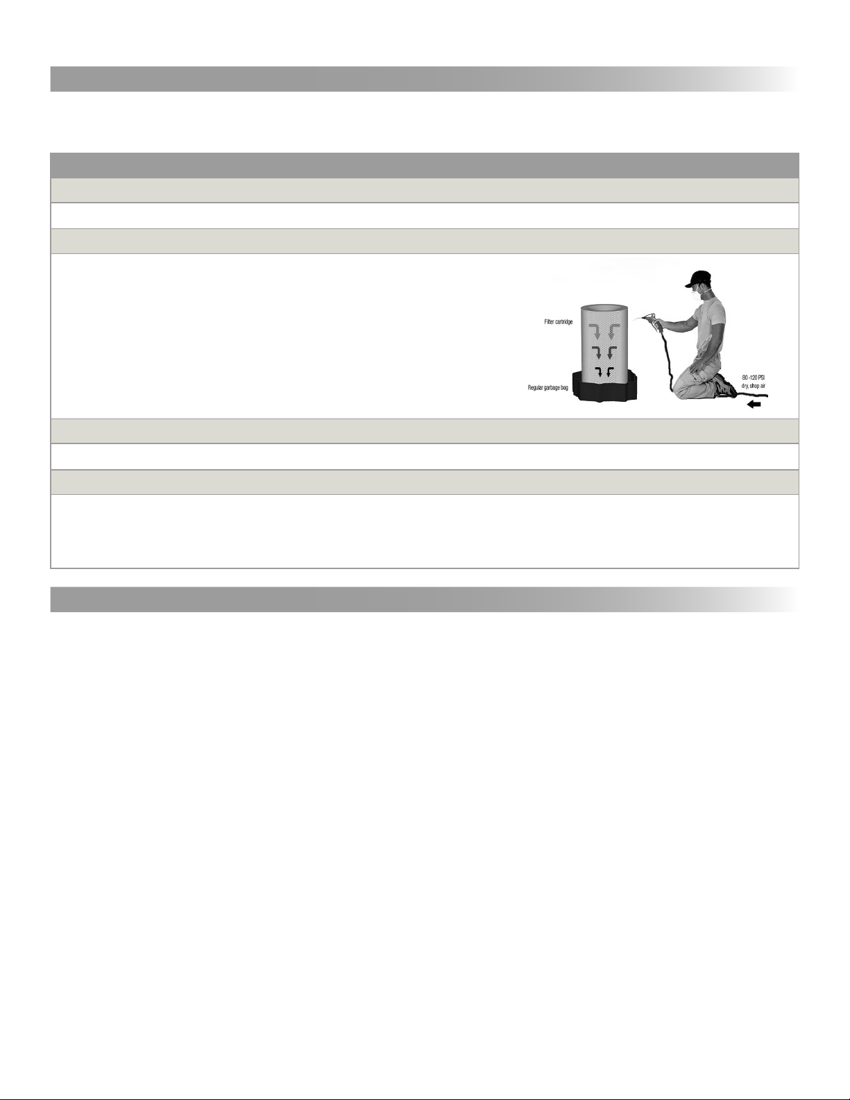
5.4 Servicing Filter ..................................................................................................................................10
5.5 Troubleshooting Procedure ..................................................................................................................11
SECTION 6 – DECOMMISSIONING ..................................................................................................................12
6.1 To Decommission this Product Safely ..................................................................................................12
6.2 Tools Required ...................................................................................................................................12
6.3 Comformity with Recycling Regulations ..................................................................................................12
APPENDIX 1A – ELECTRICAL DIAGRAM MANUAL [120 VAC] Single Phase Power .....................................................13
APPENDIX 2 – MAINTENANCE RECORD ...........................................................................................................14
APPENDIX 3 – ARM-TO-BLOWER DIRECT INSTALLATION ....................................................................................15
APPENDIX 4 – FILTER INSTALLATION .....................................................................................................16,17,18
APPENDIX 5 – EXPLODED VIEW & PART NUMBERS........................................................................................19,20
APPENDIX 6 – SAMPLES SAFETY STICKERS .....................................................................................................21
NOTES..........................................................................................................................................22,23,24,25
TERMS AND CONDITIONS TO SALES ORDERS............................................................................................26, 27
Back Cover ................................................................................................................................................28
Revised October 2019 [E N]

!
!
!
!
!
3
• Breathing smoke, fumes, or dusts produced in applications such as welding, cutting, grinding, painting, deburring
are hazardous to user’s health. Proper ventilation or use of well maintained fume extraction and/or dust collection
equipment helps the user avoid these hazards.
• Breathable contaminants may not be visible or have an odor.
• Stop operation and leave the area immediately if 1) breathing becomes dicult, 2) experience dizziness,
impaired vision, 4) or eye/nose/mouth irritation.
• Improper use can be hazardous.
• All users must carefully read and understand this instruction manual prior to use
• No objects, such as tools, should be placed on the machine.
• When moving machine, care should be taken to ensure the users feet remain clear of the wheels.
• Machine weights 474 lbs without a capture arm, proper care should be taken when moving.
• Motor should not contact any objects, and all motor repairs should be performed while the power switch is o
and the power source is disconnected. Operator should not touch motor during use.
• Blower assembly should not contact any objects, and all blower repairs should be performed while the power
switch is o and the power source is disconnected. Operator should not touch blower during use.
• For maintenance of any and all components, power switch must be o and the power source disconnected
• It is your responsibility to follow all applicable ANSI, OSHA, UL, CSA, National & Local Fire Codes, and other
regulatory guidelines covering the safe use of equipment that extracts fumes, collects dusts, and exhausts
ltered air either indoors or outdoors.
• Before use, inspect the unit for damage and verify it is working properly.
• Only qualied persons should install, operate, maintain, or repair this unit.
• Do not modify or repair the unit with parts or accessories not supplied by the manufacturer.
• Consult lter manufacturer’s instructions for lter use and reuse, including instructions for cleaning.
1.1 Symbols
1.2 Users Responsability
1.3 Fume Extraction Hazards
HOT
PARTS
MOVING
PARTS
ELECTRIC
SHOCK
WARNING!
DANGER!
This manual uses
several symbols to
highlight specic
hazards. Be familiar
with these symbols and
when you see them in
this manual, read
adjoining warning text
to avoid the hazard.
SECTION 1 - SAFETY PRECAUTIONS OF FUME & DUST EXTRACTION/COLLECTION
DO
NOT
USE
READ
BEFORE
USE
This manual contains specic cautionary statements related to worker safety.
To protect yourself and others, read this manual thoroughly and follow as directed
before use. Not all hazards of fume & dust control are listed in this manual, and
no hazards related to welding, cutting, grinding, painting, deburring
or other applications are listed. Consult a qualied safety professional.
Do not use this equipment:
• To extract combustible dusts, liquid vapors, aggressive fumes such as acids.
• To extract smoke or fumes above 180°F / 82°C.
• If the power cord has been damaged or ground (third prong) removed.
• Without a lter.

4
• Dusts from many metalwork, welding, cutting, grinding, painting, or deburring applications can be combustible.
• Do not use or install equipment where any potential for combustible fumes or dusts are present, until a
qualied person has indicated it is safe to do so.
• Never use or install equipment where the potential for combustible fumes or dusts are present without a
re/explosion protection system.
• If you are unsure if the product you purchased is correct for your application, call Fume Boss at (416) 276-9211.
1.4 Dust Collection Hazards
1.5 Safety Stickers
• This machine is equipped with safety stickers to remind operators of the inherent dangers during use and maintenance.
• The stickers are only reminders, and all safety precautions contained in this manual must be well understood
and adhered to by all users.
• See APPENDIX 6: Sample Safety Stickers for example of stickers applied to machine.
SECTION 2 - SPECIFICATIONS
2.1 Diagram & Description

Description Stage Part # Filter Area (sq. ft.) Filter
Eciency Reusable
Nanober Filter Primary FB-800-14NF 128 MERV 15 Yes
Model Motor
(H.P.)
RPM
Power
Airow
(CFM)
Cord
Length
(f t.)
Arm
Length
(f t.)
Phase
(hz)
@120V
(amps)
FUME BOSS with articulated capture arm
FB-800-015N1 1.5 1750 1P/60Hz 13.2 800 15 6.5
Model
Arm
Length
(f t.)
Arm
Diameter
(in.)
Net
Weight
(lbs.)
Product Dimensions (in.)
Width
[a]
Height
[C]
Length
[b]
FUME BOSS with articulated capture arm
FB-800-015N1 6.5 6 287 23 34 35
5
For information on inspecting and cleaning lter, or purchasing replacement lters, contact Fume Boss at (416) 276-9211
2.4 Filter Specications
2.2 Product Specications
2.3 Dimensions

!
6
3.1 To Setup or Install Safely
• Do not place unit near ammables or combustible surface.
• Refer to SECTION 2: Specications, to know the electrical requirements of the unit
you are
installing and ensure adequate input power that is properly sized, rated, and
protected.
• This unit must be grounded for safe operation.
3.2 Un-Packaging
3.4 Mounting Options
• Arm-To-Blower Direct Installation: Follow guidelines in APPENDIX 3: Arm-to-Blower Direct Installation.
3.5 Electrical Options
SECTION 3 - PRE-INSTALLATION
1. Immediately upon receiving the unit, carefully examine the carton for damage during transit.
2. Use lift forks or truck to move
3. Remove packing material.
4. Avoid tipping or inverting during handling.
5. The item serial number, model, and electrical ratings are listed on the nameplate. Record this information in
the Maintenance Record provided in APPENDIX 2: Maintenance Record, or your own preventative maintenance system.
• Single-Phase Unit: See APPENDIX 1A: Electrical Diagram [120 VAC] Single-Phase Power for wiring
instructions. Have a certied electrician install unit according to local regulations.
3.3 Tools Required
1. 7/16 Socket or Wrench
2. 9/16 Socket or Wrench
3. Torque Wrench
The tools above are required for unit assembly.

!
7
4.2 Controls
• Read and understand SECTION 1: Safety Precautions and SECTION 4: Operation
before use
• Read and understand all Material Safety Data Sheets and Manufacturer’s instructions of all
process materials, consumables, and equipment used in conjunction with this equipment.
• Keep away from all mechanical moving parts including motor, gears, and other pinch points.
• Do not use product without rst conrming if a Spark Arrestor is required and installed for
the type of dust, or fumes you are extracting and/or collection. If you are unsure, call a
Fume Boss representative at (416) 276-9211
4.1 To Operate Safely
SECTION 4 - OPERATION
• Read and understand SECTION 1: Safety Precautions and ensure SECTION 3: Pre-Installation has been
followed.
• Before plugging unit in to an input power source, look at the manufacturer’s label located on the exterior of the
unit and ensure the source is correctly sized in terms of Voltage and Amperes.
• Prior to use in your application, turn the unit ON, and perform a function test. To do so:
1. LOOK: Have the front and back doors been closed properly.
2. Turn switch to ON position.
3. LOOK: Is the unit level, stable, and that nothing is obstructing the extraction path.
4. LISTEN: Does the motor and suction sound smooth and within expected volumes.
5. FEEL: Place your hand on top of the unit and sense for unexpected vibration. Place you hand in front of
the intake hood/surface and sense for expected level(s) of suction.
• Inform all potential users of this equipment where they may nd and review this manual.
4.3 Pre-Use Checklist
• The machine controls are basic, and consist solely of a power switch with ON
and OFF positions.

8
4.4 Principles of Operation
This product is designed to capture and clean smoke and dust from medium & heavy duty welding, soldering, and
grinding applications. When operating, air is drawn in to the nozzle, passes through the 6” diameter hose, then
through the air cleaner’s ltration system, and is exhausted through the rear discharge.
This product consists of four basic components:
1. Capture Arm(s)
2. A blower
3. Cartridge Filter
4. Motor & Electrical assemblies
• The operator is to positon the machine within operating distance, and activate the caster wheel brakes.
• The operator can then position the capture arm close enough to the worksite to capture all dust and fumes that
will be produced.
• Ensuring that all safety procedures have been followed, the operator can turn on the machine and begin working.
• When not in use, the machine should be turned o.
4.5 Failure Event
If, for some reason, during operation there is an accident, a blockage occurs, the Minihelic displays abnormal pressure
dierences, or the machine begins to act abnormally, the operator should immediately shut o the machine. This is
considered a machine failure and the following steps should be taken:
1. Turn the power switch to the OFF position.
3. Seek medical attention if an accident occurred.
4. Follow the guidelines in SECTION 5: Maintenance and Troubleshooting.
Remember, under no circumstance should the machine be turned back on while performing maintenance.

!
!
!
9
SECTION 5 - MAINTENANCE & TROUBLESHOOTING
5.1 To Maintain this Product Safely
5.2 Tools Required
EYE
PROTECTION RESPIRATOR GLOVES
WASTE
CONTAINER
REPLACEMENT
FILTER
(if required)
• Read and understand SECTION 1: Safety Precautions and SECTION 4: Operation
before maintenance.
• Do not breathe the dust collected from product while changing/cleaning lters or performing
maintenance on this product.
• Disconnect power before performing any maintenance on unit, including lter inspection. The
input power to this unit is high voltage, and touching any live electrical parts can cause fatal
shocks or severe burns. Do not touch live electrical parts.
• Keep away from all mechanical moving parts including motor, gears, and other pinch points
while operating.
• Operating this unit causes some parts to heat to a point that will burn bare hands. Before
maintenance allow parts to cool, or use proper tools and personal protection equipment
during maintenance.

Frecuency Manual Reference
Pre-Use
• Perform pre-use checklist to ensure operating correctly. 4.3
Clean Filter
1. Place lter in garbage bag with the open end facing down
2. Blow o the lter cartridge using dry shop air
3. Material will collect in the bag for easy disposal
As Required – Replace Filter
1. Replace Filter
Every (12) months Inspect Basic Components
1. Clean unreadable labels and exterior surfaces
2. Capture Arm: Check for tears in ex hoses and tting of hose clamps
3. Cabinet: Look for loose wiring.
10
5.3 Routine Maintenance Schedule
The manufacturer recommends the following routine maintenance based on light-duty use in normal operating
conditions. Service more frequently if the unit is used in severe conditions.
1. Review Section 5.1: To Maintain this product Safely
2. Consult APPENDIX 4: Filter Installation.
3. Turn o power and disconnect input power cord.
4. Detach Rear Panel by rst unclasping twist-lock latches located on rear of the main body.
5. Push the Retention Rod Handle to the forward most position
6. Slide and lock the Locking Bolt in the left most position
7. Pull the Retention Rod Handle to lower the lter
8. Remove lter by gently sliding out of enclosure so as to minimize agitating dirt and dust, and place it in a bag/container.
9. Clean lter:
• Use clean/dry air only at a pressure not more than 80 psi at 12” from media.
• Direct the compressed air through the lter from the clean side, running the nozzle up and down the lter pleats.
• Do not bring either nozzle in contact with the lter media as damage is likely to occur.
10. Inspect lter for any damage and replace if necessary.
11. Clean cabinet interior of dirt and debris.
12. Reassemble:
• Pull Retention Rod Handle to lowest position to allow space for lter.
• Slide in clean lter.
• Push Retention Rod Handle to forward most position.
• Slide and lock the Locking Bolt in the right most position, ensuring it locks the Retention Rod Handle.
5.4 Servicing Filter

11
5.5 Troubleshooting Procedure
Motor
Operating
NO INTERMITTENTLY
Turn Unit
On
Motor
Operating
Air Flow
Restricted
Check Leads at
Input Power
Source
Air Flow
Restricted
Check/clean
Hood inlet &
Capture tubes
Unit Operates
Properly
Call for Service
(416) 276-9211
Fume Boss
Call for Service
(416) 276-9211
Fume Boss
Call for Service
(416) 276-9211
Fume Boss
YES
YES
YES
NO NO
Check Leads at
Unit
NO Air Flow
Restricted
Replace
Filter
NO YES
NO
YES

!
!
!
12
SECTION 6 - DECOMMISSIONING
6.1 To Decommission this Product Safely
6.2 Tools Required
6.3 Comformity with Recycling Regulations
1. 7/16 Socket or Wrench
2. 9/16 Socket or Wrench
The tools above are required for unit dismantling. Follow Section 3.5, and Appendix 3 for instructions.
• All dismantling procedures should be made in compliance with appropriate laws governing the recycling and
disposal of materials.
• This machine may contain, but is not limited to:
1. Steel
2. Plastic
3. Rubber
4. Electrical Conductors
5. Aluminum
6. Paint
7. Magnetic Material
8. Nano-Fiber Filter
9. Dust and Debris from use
• Read and understand SECTION 1: Safety Precautions and SECTION 4: Operation before
maintenance.
• Do not breathe the dust collected from product while changing/cleaning lters or performing
maintenance on this product.
• Disconnect power before performing any maintenance on unit, including lter inspection. The
input power to this unit is high voltage, and touching any live electrical parts can cause fatal
shocks or severe burns. Do not touch live electrical parts.
• Keep away from all mechanical moving parts including motor, gears, and other pinch points
while operating.
• Operating this unit causes some parts to heat to a point that will burn bare hands. Before
maintenance allow parts to cool, or use proper tools and personal protection equipment
during maintenance.

13
[120 VAC] Single-Phase Power
Disconnect power before performing any maintenance on unit, including lter
inspection. The input power to this unit is high voltage, and touching any live
electrical parts can cause fatal shocks or severe burns.
Do not touch live electrical parts.
APPENDIX 1A - ELECTRICAL DIAGRAM MANUAL
ELECTRIC
SHOCK
HAZARD
WARNING
Do not route auxiliary contact
cable in the same conduit as
motor cable
NOTE
Specic transformer wiring may
dier depending on voltage
conguration.
Units in brackets [ ] refer to
imperial system values
1.5 HP [120v]
TEFC Motor
60 Hz
[120 VAC 60 hz]
Power Supply
Motor

Date Description of Service Serviced By Location Comments
MANUFACTURER: MODEL N° FUME BOSS SERIAL N°
SERVICE LOCATION: CONTROL N°
14
APPENDIX 2 - MAINTENANCE RECORD
Fume Boss authorizes this page to be photocopied or otherwise reproduced as needed for management of
maintenance records.
Only use manufacturer approved replacement parts on this unit.

Quantity Hardware
1Mounting Plate
1Swivel Base
8 1/4’’ Bolt, Socket Cap
81/4’’ Washer
15
Capture Arm
Swivel Base
Vent Hood
STEP 1. Unpack capture arm, hood, and base.
STEP 2. Attach swivel base to mounting plate.
APPENDIX 3 - ARM-TO-BLOWER DIRECT INSTALLATION
3.1 Unpack capture arm, hood, and base
3.2 Attach swivel base to mounting plate
• Mount Swivel Base to Mount Plate.
• Tighten all Bolts (8) with Washers (8)
• Toque each bolt to 23 N m

Quantity Hardware
1 Fume Boss Assembly
1Rear Panel
2 Twist Lock Latches
Quantity Hardware
1 Fume Boss Assembly
1Locking Bolt
1Retention Rod Handle
16
• Twist and release Twist Lock Latches.
• Open Rear Panel.
STEP 1. Opening rear panel.
APPENDIX 4 - FILTER INSTALLATION
4.1 Opening rear panel for lter access
4.2 Preparing for lter
STEP 2. Preparing for lter.
• Slide and lock the Locking Bolt in the left most position.
• Pull Retention Rod Handle to allow space for lter.

Quantity Hardware
1 Fume Boss Assembly
1Locking Bolt
1Retention Rod Handle
1Filter
Quantity Hardware
1 Fume Boss Assembly
1Locking Bolt
1Retention Rod Handle
1Filter
17
4.3 Inserting lter
STEP 3. Insert clean lter.
4.4 Locking lter
STEP 4. Locking lter.
• Push Retention Rod to forward most position
• Slide and Lock the Locking Bolt to the right most
position and lock.

Quantity Hardware
1 Fume Boss Assembly
1Rear Panel
2 Twist Lock Latches
18
4.3 Closing rear panel for lter access
STEP 5. Closing rear panel.
• Close Rear Panel.
• Twist and release Twist Lock Latches.

19
APPENDIX 5 - EXPLODED VIEW & PART NUMBERS

ITEM # PART # INVERTORY # DESCRIPTION QTY
1FB_BASE INV-CAB-FUMEBOSS-BT-GB BASE FRAME 1
2 FB_SIDE R INV-CAB-FUMEBOSS-BT-GB SIDE FRAME RIGHT 1
3 FB_SIDE L INV-CAB-FUMEBOSS-BT-GB SIDE FRAME LEFT 1
4FB_TOP INV-CAB-FUMEBOSS-BT-GB TOP FRAME 1
5FB_DOOR INV-CAB-FUMEBOSS-BT-GB DOOR 1
6FB_COVER PLATE INV-CAB-FUMEBOSS-BT-GB COVER PLATE 1
7FB_CAM BRACKET INV-CAB-FUMEBOSS-BT-GB SUPPORT BRACKET 4 2
8FB_STOP BRACKET INV-CAB-FUMEBOSS-BT-GB STOP BRACKET 1
9FB_LATCH BRACKET INV-CAB-FUMEBOSS-BT-GB LATCH BRACKET 1
10 FB_CAM LOCK INV-CAB-FUMEBOSS-BT-GB CAM LOCK 1
11 FB_ADAPTER INV-CAB-FUMEBOSS-BT-GB MOUNT PLATE 1
12 FB_HANDLE INV-CAB-FUMEBOSS-BT-GB HANDLE BAR 1
13 HARD INV-FILT-14NF NANOFIBER FILTER 1
14 HARD INV-56TC-015-12-1800 MOTOR, 1.5HP 56TC TEFC [115/230-1-60] 1800 RPM 1
15 HARD INV-WHEL-0081 ALUMINUM WHEEL, 1.5HP 1
16 HARD INV-C AST-0028 SWIVEL CASTER, Ø4” WHEEL, WITH BRAKE 4
17 HARD INV-HARD-0465 SLIDE BOLT LATCH 1
18 HARD INV-CRTL-0090 MANUAL STARTER BOX 1
19 HARD INV-HARD-0446 LIFT & TURN LATCH 2
20 HARD INV-HARD-0444 HINGE.ADJUSTABLE W/PINS 2
20
PARTS NUMBERS
Table of contents
Popular Scrubber manuals by other brands

Ice
Ice SCRUB 80 D Use and maintenance manual

Windsor
Windsor Saber Compact QSC20 Instrucciones de funcionamiento

Caple
Caple CGI900SS Installation and operating instruction booklet

Zipper Mowers
Zipper Mowers ZI-ASA550 Operation manual

Fimap
Fimap GL Pro Use and maintenance manual

Pacific
Pacific Z210 Parts & operating manual

Nederman
Nederman ORIGINAL 535 Series instruction manual

Festool
Festool CT 26 E AC Original operating manual

Crescent
Crescent CS7010 Service manual

Ghibli & Wirbel
Ghibli & Wirbel POWER EXTRA 11 Use and maintenance

Kärcher
Kärcher KM 90/60 R P operating instructions

RPS
RPS Magnum 26" Disk operating instructions