Funke+Huster Fernsig 2014/2 User manual

Feuermelder / Fire alarm
Handauslöseeinrichtung und Stopptaster /
Manual triggering solution and Stop Device
•
Bereiche der Zone 1 und 2,
21 und 22
•
Schutzklasse II und III
•
Schutzart IP 66 / IEC 60529
•
Temperaturbereich:
-55ºC bis +70ºC oder +65ºC
•
Kunststoffgehäuse:
glasfaserverstärktes
Polyester
•
Alle Metallteile
aus V4A-Edelstahl
•
Robuste Konstruktion
•
zertifiziert nach
Verordnung (EU)
Nr. 305/2011
für Bauprodukte
FHF BA 2013-1 01/16 1
Abb. / Fig. 1
Abmessungen / Dimensions
88 136*
155
75 *
138
* Befestigungsmaße /
Fastening measurements
• Areas of Zones 1 and 2
,
21 and 22
• Class II and III
• IP 66/IEC 60529
degree of protection
• Temperature range:
-55ºC to +70ºC
or +65ºC
• Plastic housing:
Fibre-reinforced polyester
• All metal parts consist of
stainless steel (V4A quality)
• Robust design
• Certified according
to the Regulation (EU)
No. 305/2011
for construction products
Typ / Type 2014/2 / 2014/2-GLU

Hinweis
Vor Installation des Gerätes ist die
Bedienungsanleitung sorgfältig zu
lesen. Bei eventuellen S häden und
Ansprü hen gelten die „Allgemeine
Lieferbedingungen für Erzeugnisse
und Leistungen der Elektroindustrie“
in Ihrer jeweils letzten Fassung.
Anwendung
Die Feuermelder Typ 2014/2 und
2014/2-GLU dienen der manuellen
Alarmauslösung in explosionsge-
fährdeten Berei hen. Die
Zünd-
s hutzart
erlaubt dabei den Einsatz
des Melders in allen Ex-Berei hen
der Zonen 1 und 2, 21 und 22.
Aufbau
Der Explosionss hutz wird dur h den
Einbauraum und den Ans hlussraum
in der Zünds hutzart „erhöhte
Si herheit“ gewährleistet. Zwe ks
Explosionss hutz sind der S halt-
kontakt und die Module gas di ht ver-
gossen. Das Gehäuse ist vollständig
aus Kunststoff gefertigt. Hierdur h
wird zum einen der hohe Korrosions-
s hutz, zum andern die S hutzklasse
II und III gewähr leis tet. Ein Potential-
ausglei hsleiter ist daher ni ht erfor-
derli h. Hohe Robustheit, mit den
Wandstärken von mind. 8 mm sind
weitere Merkmale der Konstruktion.
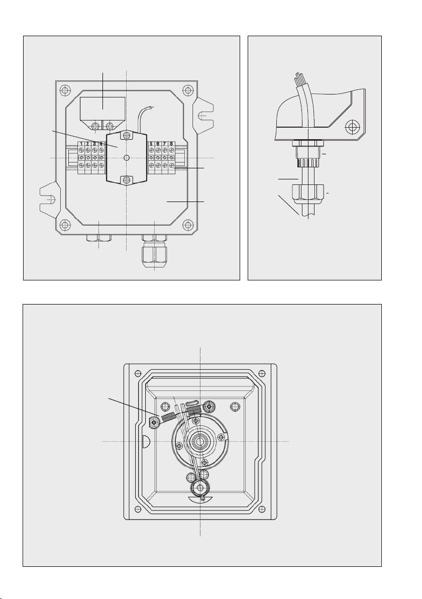
Montage
Der Feuermelder ist auf einer senk-
re hten festen Flä he (Wand, Träger
et .) zu montieren. Die äußeren
Abmessungen und die Befes -
tigungsmaße sind der Abb. 1 zu
ent nehmen. Der Unter grund (Wand,
Träger et .) soll so bes haffen sein,
dass die Befes tigungsfüße si her
aufliegen und dass er das Gewi ht
des Gerätes von a. 1,8 kg dauerhaft
tragen kann. Für die Befestigung
sind S hrauben mit Dur hmesser
5 mm, S heiben und Federringe zu
verwenden. Abstand zwis hen Boden
und Dru kknopf 1400 ± 200 mm.
Hinweis
Das Gehäuse des Feuermelders
besteht aus zwei Gehäuseteilen:
a) Gehäuseunterteil (Ans hlussraum)
b) Gehäuseoberteil (De kel mit Tür)
Für die Montage ist wie folgt
vorzugehen:
1) Befestigungsbohrungen entspre-
hend Abb. 1 herstellen
2)
Gerät waagere ht auf die Rü k-
seite legen, den Sondervers hluss
der Tür mit einem S hrau bendreher
für Innen se hs kants hrauben (Größe
4 mm) lösen und ans hließend die
Tür öffnen.
3) Vier De kels hrauben mit einem
S hraubendreher lösen und
De kel mit Tür von dem Ge -
häuseunterteil abnehmen.
Achtung Auf Sauberkeit der
De keldi htung a hten.
4) Gehäuseunterteil (Ans hlussraum)
mit den Befestigungss hrauben,
S heiben und Feder ringen an
die Wand montieren.
Installation
Bei den werkseitig bestü kten KLE
ist die beige fügte Betriebsanleitung
zu be a hten. Muss auf Grund einer
anderen Ans hlussleitung die Kabel-
einführung gewe hselt werden, so
ist Punkt 10 im Kapitel der Benutzer -
informationen zu bea hten. Bei Ver-
legung der Ans hlussleitung ist im
Berei h der Kabeleinführung auf
Sauberkeit und gerader Führung zu
a hten.
Für den Ans hluss der Brandmelde-
leitung ist wie folgt vorzugehen:
• Dru ks hraube der Kabeleinfüh-
rung lösen und abnehmen
• Kabelaußenmantel (für die In -
stallation des Ans hlussraumes)
abisolieren und dur h Dru k s hrau -
be und Kabelvers hraubung führen.
•
Einzeladern an den Enden a.
5-6 mm abisolieren damit ein
si herer Kontakt gewährleistet
ist. Die Verdrahtung im Inneren
des Ans hlussraumes darf ni ht
an das Verriegelungsystem des
Knopfes gelangen, damit eine
Verrastung si hergestellt ist. Die
Aderisolation der Leiter muss soweit
an der Ans hlussklemme liegen,
dass zwis hen den leit fähigen Teilen
mindestens 3 mm Luft- und Krie h-
stre ke vorhanden sind.
• Zur Montage der KLE sind nur
geeignete Werkzeuge zulässig!
• Der Kabelans hluss ist nur für
fest verlegte Leitungen geeignet.
• Die Installation der Einzeladern,
sind dem S haltbild auf dem
jeweiligen Modulgehäuse im
Ans hlussraum zu entnehmen.
Die Module sind werkseitig bis
zur Ans hlussklemme verdrahtet.
Na h Installation der Ans hluss -
leitung ist der De kel parallel auf
das Ans hlussgehäuse zu setzen.
Die vier De kels hrauben sind
glei hmäßig, s hrittweise über Kreuz
anzu ziehen mit 3 bis 3,2 Nm. Glas
oder Hinweiss hild einsetzen. Tür
s hließen und den Sonderver-
s hluss vers hrauben.
Glas einsetzen (ersetzen)
Das Glas kann ohne Werkzeug in
die geöffnete Tür eingesetzt werden.
Hierzu ist der Sondervers hluss der
Tür zu lösen und die Tür zu öffnen.
Ans hließend ist das Glas in die
beiden Führungsstege der Türrü k -
seite vorsi htig einzusetzen.
Achtung (Das Glas kann bei
offener Tür lei ht geneigt sein.) Tür
s hließen und den Sonderver-
s hluss vers hrauben.
Beim Auswe hseln eines zers hla-
genen Glases sind alle Glassplitter
sorgfältig (eventuell mit einem Pinsel)
zu beseitigen, damit Verletzungen
vermieden werden und die Tür ein-
wandfrei zu vers hließen ist.
Beschilderung
Der Feuermelder ist dur h norm-
gere hte Bes hilderung zu kenn-
zei hnen. Werksseitig liegen dem
Feuermelder S hilder bei. Der Ein-
ri hter muss die S hilder entspre-
hend des Betriebszustandes bzw.
der Anforderungen auswählen und
auf dem Gerät befestigen.
Rücksetzen des Knopfes
(bei verrastender Ausführung)
Der Knopf kann nur bei geöffneter
Tür mit dem glei hen S hrauben-
dreher für Innense hskants hrauben
(Größe 4 mm) zurü kge stellt werden,
mit dem die Tür zuvor geöffnet
wurde. Hierzu die Tür öffnen und
den S hraubendreher in die Innen-
se hskants hraube unter dem Aus -
löseknopf einsetzen und lei ht na h
re hts drehen, dabei kommt der
gedrü kte Knopf wieder in seine
Ausgangs position zurü k.
Änderung der Knopffunktion
Der Auslöseknopf kann wahlweise
auf „verrastend“ oder „ni ht ver-
ras tend“ entspre hend der Abb. 4.
geändert werden.
•verrastend:
der Knopf bleibt na h Betätigung
gedrü kt, er kann nur dur h die
Entriegelungss hraube (Innen-
se hskants hraube) zurü kge-
stellt werden.
•nicht verrastend:
Der Knopf kehrt na h dem
Drü ken sofort in seine Aus -
gangs stellung zurü k (Taster).
•Umbau:
Dazu wird das Gehäuse wie be-
s hriebengeöffnet.Auf der Rü k-
seite des Gehäuseoberteils ist
eine Rü kstellfeder zu sehen.
a) Bei der verrastenden Funktion
zieht die Feder den Verriege-
lungsstab zum Knopf hin.
2

3
Technische Daten
Typ 2014/2 und 2014/2-GLU
Gerätebezei hnung Feuermelder Typ B na h EN 54-11
oder Handauslöseeinri htung und Stopptaster na h EN 12094-3
Gehäuse Glasfaserverstärktes Polyester
Gehäusefarbe Feuermelder: rot RAL 3000
Handauslöseeinri htung: gelb RAL 1021
Stopptaster: blau RAL 5015
Oberflä henwiderstand Elektrostatis h leitfähig
Kabeleinführung 1x M16 x 1,5 mm
Blindvers hraubung 1x M16 x 1,5 mm
Lagertemperatur -60°C bis +85°C
S haltkontakt Typ 366 (We hsler, vergossen), II 2 G Ex d II C
Kontaktbelastbarkeit max. 1 A / 250 VAC 0,25 A / 250 VDC
Betriebsgebrau hslage nur Wandmontage
Betriebsbedingungen in Räumen oder im Freien einsetzbar
Ans hlussklemmen bis 4 mm2fein- oder eindrähtig
Abmessungen a. 136 x 138 x 88 mm
Gewi ht a. 1,8 kg
S hutzklasse II und III (kein Potentialausglei h erforderli h)
S hutzart IP 66 (gemäß IEC 529/EN 60529)
Ex-Bes heinigung Feuermelder / Handauslöseeinri htung und Stopptaster PTB 97 ATEX 3197
Handfeuermelder für Brandanlagen
VdS Anerkennung Handfeuermelder G 297060
VdS Zertifikate Handfeuermelder 0786-CPD-20367
Handauslöseeinrichtung für Gaslöschanlagen
VdS Anerkennung Handauslöseeinri htung G 207146
VdS Zertifikat Handauslöseeinri htung 0786-CPD-20346
Stopptaster für Gaslöschanlagen
VdS Anerkennung Stopptaster G 210019
VdS Zertifikat Stopptaster 0786-CPD-20944
Bauarten Zündschutzart Betriebsumgebungstemperatur
- mit Modul und Taster II 2 G Ex d e mb IICT6 Gb -55°C울Ta 울+65°C
- mit Modul und Taster II 2 G Ex d e mb IICT5 Gb -55°C울Ta 울+70°C
- ohne Modul mit Taster II 2 G Ex d e IICT5 Gb -55°C울Ta 울+70°C
- alle Bauarten II 2 D Ex tb IIIC T100°C Db IP66
b) Bei der ni ht rastenden Funktion
zieht die Feder den Verriegelung s-
stab vom Knopf weg. Die Feder
wird mit der Befes tigungs s hrau be
je na h gewün s h ter Funktion
re hts oder links vom Verriege-
lungstab in die Befestigungs -
bohrung ges hraubt.
Soll ein Umbau in eine der beiden
Varianten gewüns ht werden, so
wird die Befestigungss hraube der
Feder gelöst, die Feder zur ent-
spre henden Seite gelegt und
mittels S hraube wieder befestigt.
Ans hließend De kel montieren
und Tür wie bes hrieben s hließen.
Wartung und Pflege
Der Feuermelder ist wartungsfrei.
Denno h sollte in Einsatzberei hen
mit starker Vers hmutzung dur h
Staub, Fett, Öl usw. von Zeit zu Zeit
eine Reinigung dur hgeführt werden.
Mit einem feu hten Reinigungstu h
ist das Gerät abzu wis hen.
Aufrechterhaltung
der Funktionsfähigkeit
Um die Betriebssi herheit des
Feuermelders zu bewahren ist es
notwendig, das Gerät von Zeit zu
Zeit auf si htbare S häden zu
untersu hen. Obwohl das Gerät für
den rauhen Industrieberei h gebaut
wird, ist ni ht auszus hließen, dass
z.B. dur h große Stoß- oder
S hlageinwirkung et . S häden
ent stehen, die eine Funktion oder
Di htigkeit eins hränken. Defekte
Teile dürfen nur dur h Originalteile
ausgewe hselt werden. Ort und Art
der Befestigung muss s hwin-
gungs- und vibrationsfrei sein,
gemäß EN 12094-3.
Handauslöseeinrichtung
und Stopptaster
Das Gerät ist weitestgehend bau-
glei h mit dem Feuermelder. Er
wird jedo h ni ht rot la kiert, son-
dern in gelb bzw. blau geliefert. Der
Einsatz ist kundenspezifis h und
muss jeweils mit der Werksfeuer-
wehr oder den sonst zuständigen
Brands hutzbehörden abgestimmt
werden. Die Handauslöseeinri h-
tung und Stopptaster gemäß
EN 12094-3, ist zur Ansteuer ung
von Lös hanlagen vorgesehen.
In allen anderen Punkten gilt die
Gebrau hsanweisung au h für den
Sondermelder.
Recycling
Die Komplett-Entsorgung des
Gerätes erfolgt über den Elek -
tronikabfall. Bei der Demontage
des Gerätes sind die Komponenten
Kunststoff, Metalle und Elek tronik
separat zu entsorgen.
In jedem Fall sind die Ent sor gungs -
be din gun gen des jeweiligen Ein-
satzlandes zu bea hten.

Note
Please read the User’s Guide are-
fully prior to installation of the devi e.
Any damage or laims are subje t
to the latest version of the “General
Terms of Delivery for Produ ts and
Servi es of the Ele tri Industry“.
Application
The fire alarm devi es of type
2014/2 and 2014/2-GLU are
designed for manual triggering of
alarms in hazardous areas. The
type of prote tion allows the alarm
to be operated of the zones 1 and
2
, 21 und 22
.
Design
The en losure and the “in reased
safety” lass of prote tion of the
terminal room guarantee hazardous
area prote tion. For reasons of
explosion prote tion the swit h
onta t and the modules are gas
tight embedded. The housing is
ompletely made of plasti . This
ensures the high level of orrosion
prote tion as well as Class II and III.
No equipotential bonding ne essary.
Further design hara teristi s are
profound ruggedness and minimum
8 mm thi k walls.
Mounting
The fire alarm should be mounted
on a verti al, fixed surfa e (wall,
girder, et .). The outer dimensions
and the fastening measurements
an be found in fig. 1.
The mounting surfa e (wall, girder)
must be able to provide a stable
platform for the fastening feet, and
it must be able to arry the weight
of the devi e of approx. 1.8 kg on
a long-term basis. For fastening
purposes, s rews with a diameter
of 5 mm, washers and spring lo k
washers should be used. Distan e
between ground and push button
1400 ± 200 mm.
Note
The fire alarm housing onsists of
two parts:
a) Lower part of the housing
(terminal room)
b) Upper part of the housing ( over
with door)
Proceed as follows to mount
the device:
1) Produ e the fastening bores
a ording to figure 1
2) Pla e the devi e horizontally on
its ba k, loosen the spe ial lo k
of the door using a s rew driver
for hexagon so ket s rews (size
4 mm), and open the door.
3) Use a s rewdriver to loosen four
over s rews and remove the
over, in luding the door, from
the lower part of the housing.
Warning Make sure the over
seal is lean.
4) Mount the lower part of the hou-
sing (terminal room) on the wall,
using the fastening s rews,
washers and spring lo k washers.
Installation
In ase of fa tory fitted able
glands the atta hed operating
instru tions have to be onsidered.
If, due to the use of another on-
ne tion able, the able gland has
to be repla ed, please observe
item number 10 in the User Infor-
mation hapter. The area surroun-
ding the able gland should be
kept lean, and the onne ting
able should be laid in a straight
line in this area.
Pro eed as follows to onne t the
fire alarm able:
•
Loosen and remove the able
gland pressure s rew
•
Remove isolating outer able
sheath (for installation of the ter-
minal room) and guide it through
the pressure s rew and the
able gland.
•
Remove approx. 5-6 mm of the
isolation from the end of the
ondu tors, in order to establish
good ele tri al onta t. The wiring
on the inside of the terminal room
must not rea h the lo king system
of the button, in order to ensure
the lo king system works properly.
The ondu tor isolation of the
able must extend so far
towards the terminal that the
ondu tive parts are separated
by at least 3 mm of air and ree-
pan e distan e.
• Use only suited tools for instal-
ling the able glands.
• The able onne tion is suited
only for permanent ables.
•
How to install the ondu tors is
shown on the wiring diagrams
on the module housings in the
terminal room. The modules are
fa tory wired to the terminal.
After installation of the onne ting
able, pla e the over in parallel on
the onne ting housing.
The four over s rews must be
tightened evenly, step by step and
rosswise with 3,0 to 3,2 Nm.
Insert glass or an information label.
Close the door and s rew the
spe ial lo k tight.
Insert (replace) glass
The glass an be inserted into the
open door without the use of tools.
In order to do this, you must loosen
the spe ial door lo k and open the
door. Then insert the glass arefully
in both guide rails on the ba kside
of the door.
Warning (When the door is open
the glass may be slanting slightly.)
Close the door and s rew the
spe ial lo k tight.
When repla ing a broken glass, all
splinters of glass should be meti u-
lously removed (if ne essary using
a brush), in order to avoid injuries
and make sure the door an be
losed without problems.
Labelling
The fire alarm should be labelled
a ording to all appli able stan-
dards.Upon delivery, fa tory-provi-
ded labels for the fire alarm were
in luded in the box. The fitter must
sele t the labels a ording to the
operating ondition or the demands,
and fasten them on the devi e.
Resetting the button (locking
version)
The button an only be reset while
the door is open, and with the same
s rewdriver for hexagon so ket
s rews (size 4 mm), with whi h the
door was opened. Open the door
and insert the s rewdriver into the
hexagon so ket s rew below the
trigger button, and turn slightly to
the right, this releases the depressed
button to its original position.
Change the button function
The trigger button may be hanged
to “lo king” or “non-lo king”, a or -
ding to figure 4.
•
locking:
Having been pressed, the button
stays depressed and an be reset
by the unlo k-s rew (hexagon
so ket s rew) only.
• non-locking:
Having been pressed, the button
immediately returns to its original
position (push button).
• Modification:
Open the housing a ording to the
des ription. On the ba kside of the
upper part of the housing you will
see a reset spring.
a) In the ase of the lo king fun tion,
the spring pulls the lo king bar
towards the button.
4

b) In the ase of the non-lo king
fun tion, the spring pulls the
lo king bar towards the button.
Depending on the desired fun -
tion, the spring is s rewed into
the fastening bore to the right or
to the left of the lo king bar,
along with the fastening s rew.
In order to modify the devi e by
hanging to one of these varieties,
you will have to loosen the faste-
ning s rew of the spring, push the
spring to the side that orresponds
with the desired fun tion, and
fasten the spring with the s rew
again. Then mount the over and
lose the door a ording to the
des ription.
Care and maintenance
The fire alarm is maintenan e-free.
Still, if the operating area is highly
ontaminated by dust, fat, oil et .,
the devi e should be leaned from
time to time. Use a moist loth to
dust off the devi e.
Maintaining good working order
In order to maintain the operability
of the fire alarm, the devi e must
be he ked for visual damage from
time to time.
Although the devi e is being manu-
fa tured for use in rough industry
environments, it is possible that
damage ould ensue due to the
impa t of for instan e heavy strikes
or blows, and that this ould put
restri tions on a fun tion or redu e
tightness. Defe tive parts may be
repla ed by original parts only.
The
pla e and kind of fastening must be
vibration free, in a ordan e with EN
12094-3.
Manual triggering and
stop
device
The design of the devi e is to a
great extent identi al with that of
the fire alarm. The devi e version
however, does not ome in red, but
in yellow or blue. Operation is
ustomer spe ifi and has to be
agreed on with the ompany fire
brigade or the responsible fire pre-
vention authorities.
The manual triggering and stop
devi e a ording to EN 12094-3
has been designed to ontrol
extinguishing systems.
In all other regards, the operating
manual is valid for the spe ial
alarm, too.
Recycling
The devi e may be ompletely
re y led as ele troni waste.
When the devi e is disassembled,
plasti s, metals and ele troni s are
to be disposed of separately.
In every single ase the national
requirements and regulations for
waste disposal must be observed.
Technical Specifications
Type 2014/2 and 2014/2-GLU
Devi e name Fire alarm Type B a ording to EN 54-11
or manual triggering and stop devi e a ording to EN 12094-3
Housing Fibre-reinfor ed polyester
Housing olour Fire alarm: Red RAL 3000
Manual triggering: yellow
RAL 1021
Stop devi e: blue
RAL 5015
Surfa e resistan e Ele trostati ally ondu tive
Cable gland 1x M16 x 1.5 mm
Blind plug 1x M16 x 1.5 mm
Storage temperature -60°C to +85°C
Swit h onta t Type 366 (two-way-swit h, embedded), II 2 G Ex d II C
Swit h reliable load max. 1 A / 250 VAC 0.25 A / 250 VDC
Operating utilization position Wall mounting only
Operating onditions Indoors or outdoors
Conne ting terminals Up to 4 mm2fine-wired or multiwired
Dimensions Approx. 136 x 138 x 88 mm
Weight Approx. 1.8 kg
Expl. prote tion lass II and III (no bonding ondu tor ne essary)
Prote tion degree IP 66 (a ording to IEC 529/EN 60529)
Ex- ertifi ate Fire alarm / Manual triggering and stop devi e
PTB 97 ATEX 3197
Manual fire alarm device for fire alarm systems
VdS approval Manual fire alarm devi e G 297060
VdS ertifi ate Manual fire alarm devi e 0786-CPD-20367
Manual triggering solution for gas extinguishing systems
VdS approval Manual triggering solution G 207146
VdS ertifi ate Manual triggering solution 0786-CPD-20346
Stop device for gas extinguishing systems
VdS approval Stop devi e G 210019
VdS ertifi ate Stop devi e 0786-CPD-20944
Designs Type of protection Ambient operating temperature
- with module and push button II 2 G Ex d e mb IIC T6 Gb -55°C울Ta 울+65°C
- with module and push button II 2 G Ex d e mb IIC T5 Gb -55°C울Ta 울+70°C
- without module, with push button II 2 G Ex d e IIC T5 Gb -55°C울Ta 울+70°C
- all designs II 2 D Ex tb IIIC T100°C Db IP66
5

Abb. / Fig. 4
verrastend /
lo king
ni ht verrastend /
non-lo king
Verrastungsschema / Locking diagram
6
Abb. / Fig. 2
Ans hluss-
klemmen /
Conne ting
terminals
Ans hluss-
raum /
Terminal
room
Modul / Module
S halter /
Swit h
Anschlussplan / Wiring diagram
Abb. / Fig. 3
Brand-
melde-
leitung /
Fire alarm
able
Vers hraubung /
Cable gland
Dru ks hraube /
Pressure s rew
Kabeleinführung / Cable gland

7

8

9

Änderungen vorbehalten 05/00
Subje t to hange without noti e
Sous réserve de modifi ations
Ident.-Nr. BA
10
Bei diesem Betriebsmittel handelt es si h um ein Ex II Gerät, speziell für den Betrieb in rauer
Industrieumgebung. Bitte bea hten Sie die na hstehenden Warn- und Si herheitshinweise.
1. Das Gerät darf nur an der vorges hriebenen Spannung anges hlossen und betrieben werden.
Die für das Gerät vorges hriebene Betriebsspannung ist dem Typens hild zu entnehmen.
Es ist auf einen ordnungsgemäßen Ans hluss zu a hten.
2. Das Gerät darf nur unter den angegebenen Umgebungsbedingungen betrieben werden.
Z.B. zu hohe oder zu niedrige Umgebungstemperaturen sind ni ht zulässig.
3. Es ist darauf zu a hten, dass Gerät, Ans hlussleitung usw. ni ht bes hädigt sind. Im be -
s hädigten Zustand ist das Betreiben des Gerätes ni ht zulässig.
4. Der Ans hluss und die Inbetriebnahme darf nur von einem Fa hmann erfolgen.
5. Bei dem Betrieb des Gerätes sind die gesetzli hen und gewerbli hen Vors hriften,
Unfallverhütungsvors hriften, sowie elektris he Bestimmungen zu bea hten.
6. Bei Reparaturen sind nur Original-Ersatzteile zulässig, die fa hgere ht gewe hselt wer den
müssen. Andere Austaus hteile können zu S häden führen.
7. Vor einer Instandsetzung oder einem Austaus h des Gerätes muss es von der Spannungs-
versorgung getrennt werden. Wenn eine Wartung oder eine Reparatur unter Spannung un -
vermeidbar ist, darf das nur von einem unterwiesenen Fa hmann ges hehen.
8. Die vorges hriebene Gebrau hslage ist zu berü ksi htigen.
9. Das We hseln oder Ergänzen von Modulen darf nur von einem Fa hmann dur hgeführt
werden. Es sind nur Module zu verwenden, die zum Einbau in dieses Gerät bes heinigt sind.
10. Die zur Verwendung vorgesehene Signalleitung muss für die Betriebsumgebungstemperatur
geeignet sein.
11. Kabeleinführungen, Blindvers hraubungen und Vers hlussstopfen müssen den S hutzgrad
IP 66 gemäß EN 60529 besitzen. Zusätzli h müssen die genannten Teile der Zünds hutzart
Ex e II entspre hen und eine gesonderte Bes heinigung einer anerkannten europäis hen
Prüfstelle haben.
Bei Ni hteinhaltung der zulässigen Temperaturen ist ein me hanis h ges hützter Anbau vor-
zusehen, damit z.B. der S hutz vor herabfallenden Gegenständen besteht.
12. WARNUNG! Gerät nur feu ht reinigen!
Das Gerät darf ni ht in einer Umgebung von stark ladungserzeugenden Prozessen, insbeson-
dere bei der Anwesenheit geladener Teil hen (z.B. Elektronen von Ho hspannungselektroden,
strömenden Pulverteil hen oder Flüssigkeiten) betrieben werden!
13. Änderungen des Produktes die dem te hnis hen Forts hritt dienen sind au h ohne vorherige
Ankündigung mögli h.
Benutzerinformation

11
This devi e is an Ex II devi e espe ially designed for use in rough industrial environments. Please note
the following warnings and se urity information.
1. The devi e may only be onne ted to and operated at the voltage it was designed for. The
required operating voltage for the devi e an be found on the nameplate. Make sure the
onne tions are in perfe t order.
2. The devi e may be operated solely under the stated ambient onditions. For instan e, too high
or too low ambient temperatures are not allowed.
3. Make sure the devi e, the onne ting able, et . are not damaged. If the devi e is damaged, it
may not be operated.
4. Only a trained te hni ian may onne t the devi e and put it into operation.
5. While the devi e is in operation please follow all relevant legal and professional regulations, the
legally required pre autions to be taken to prevent a idents, and laws and regulations governing
the use and onne tion of ele tri devi es.
6. In ase of repairs, use only original spare parts, whi h must be hanged by someone with pro-
fessional skills. Other spare parts may ause damage.
7. Before the devi e is repaired or repla ed, it must be dis onne ted from the power supply. If the
maintenan e or repair of a live devi e annot be avoided, this must be done by authorised
personnel only.
8. Take into onsideration the required operating position.
9. Repla ing or amending modules must be arried out by a trained te hni ian only. Use only
modules that are ertified for installation in this devi e.
10. The signal able must be suited for the operating ambient temperature.
11.
Cable glands, blind plugs and plugs must have the IP 66 degree of prote tion, a ording to
EN 60529. Furthermore, the above-mentioned parts must omply with the Ex e II lass of
prote tion and be espe ially ertified by a re ognized European test agen y.
In ase of non- omplian e with permissible temperatures, a me hani ally prote ted atta h-
ment is to be allowed for to provide prote tion, e.g. from falling obje ts.
12. WARNING! Only lean devi e with a damp loth!
The devi e may not be operated in the vi inity of strong harge generating pro esses, in
parti ular in the presen e of harged parti les (e.g. ele trons from high voltage ele trodes,
surging powder parti les or liquids)!
13. This produ t is subje t to te hni al improvements without prior noti e.
User information

FHF Funke+ Huster Fernsig GmbH
Gewerbeallee 15-19 · D-45478 Mülheim an der Ruhr · Web:
www.fhf.de
Phone +49 - 208-8268-0 · Fax +49 - 208-8268-286 ·
Mail: info@fhf.de
Orders: fhf-orders@eaton. om · Requests: fhf-sales@eaton. om
Support: fhf-support@eaton. om
Änderungen und Irrtum vorbehalten
Subje t to alterations or errors
This manual suits for next models
1
Table of contents
Languages:
Popular Fire Alarm manuals by other brands

Cooper Notification
Cooper Notification RSS-24MCC installation instructions

Notifier
Notifier 002-439 Installing

Awex
Awex MCP / ROP 21 Assembly instructions

Kidde
Kidde GSA-M278 Installation sheet

Tyco Fire Product
Tyco Fire Product Alpha 4 Installation and operating instructions

Bosch
Bosch FPA-5000 Networking guide

Simplex
Simplex InfoAlarm 4100U Operator's manual

Honeywell
Honeywell MA Series Operation manual

Wheelock
Wheelock MT-12-LS installation instructions

Mircom
Mircom QX-mini Installation and operation manual

Teletek electronics
Teletek electronics SensoIRIS WSST Installation instruction

Ziton
Ziton ZP755BV-4P Installation sheet