Funktion-one F1201 User manual

2
Contents
F1201 User Guide............................................................................................................................... 1
1Thank you.................................................................................................................................. 2
2Receiving and unpacking ............................................................................................................ 3
3Handling .................................................................................................................................... 4
4Introduction .............................................................................................................................. 4
4.1 Features .......................................................................................................................................................4
4.2 Specifications ...............................................................................................................................................5
5Safety first ................................................................................................................................. 6
5.1 Mechanical safety ........................................................................................................................................6
5.2 Electrical and fire safety...............................................................................................................................7
5.3 Hearing safety ..............................................................................................................................................7
6Coverage ................................................................................................................................... 8
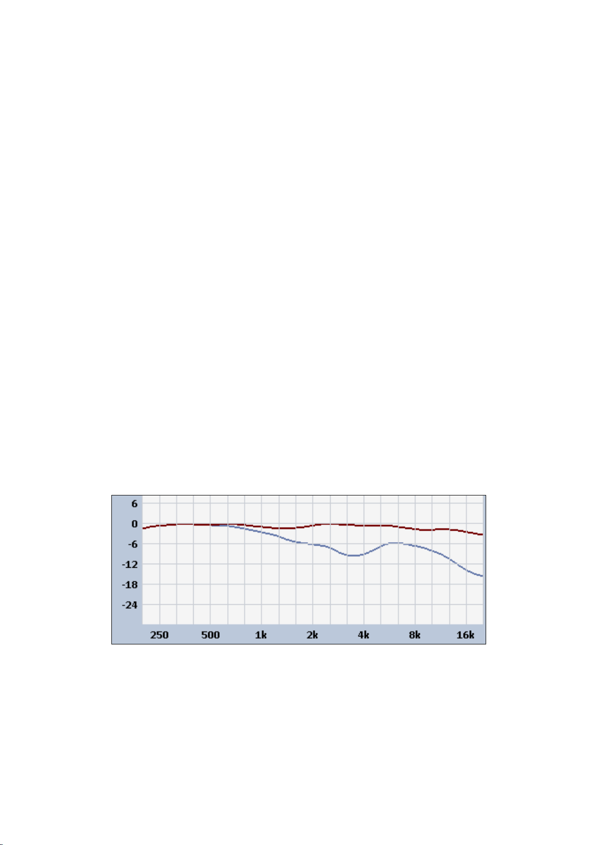
6.1 Vertical and horizontal responses................................................................................................................8
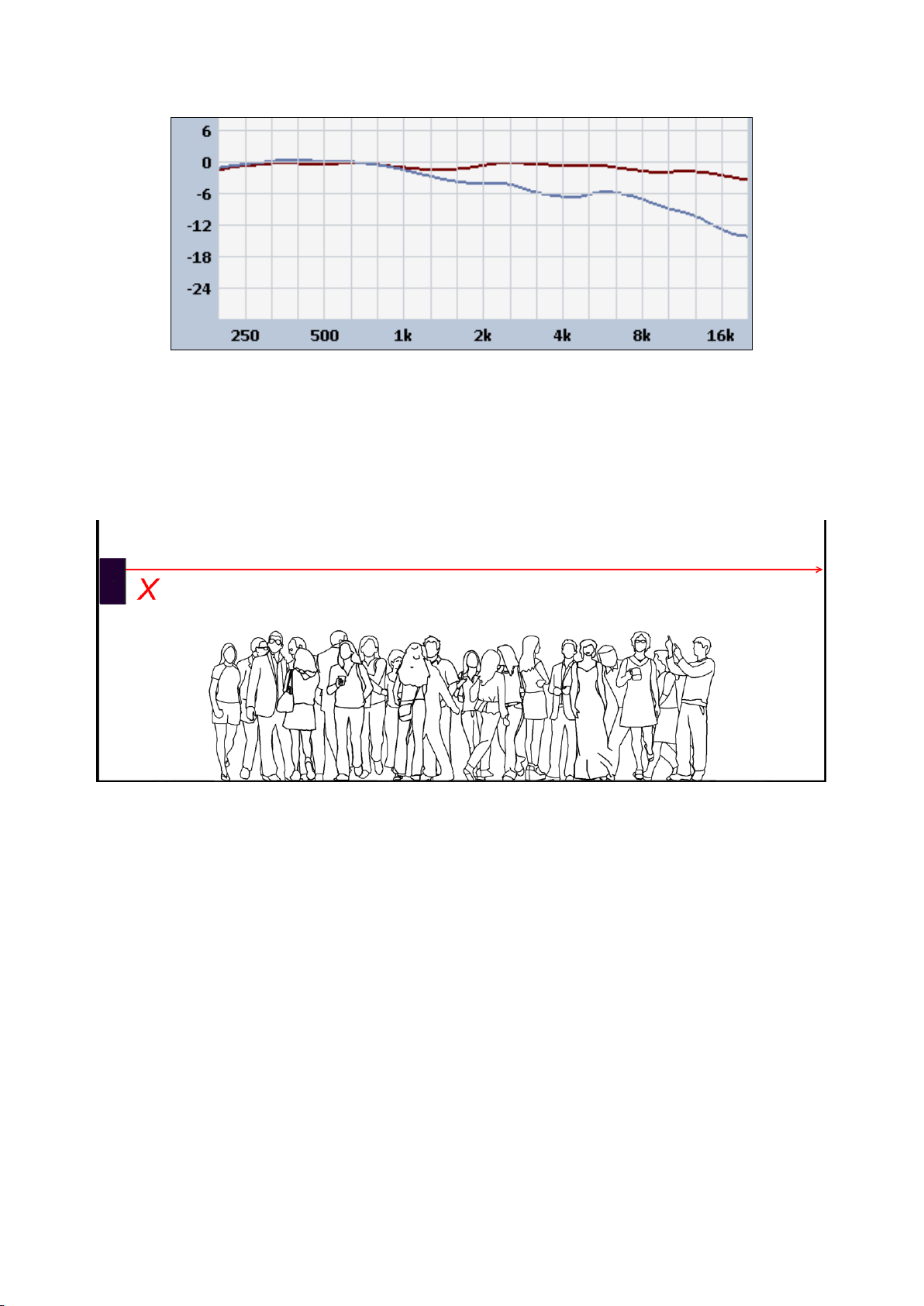
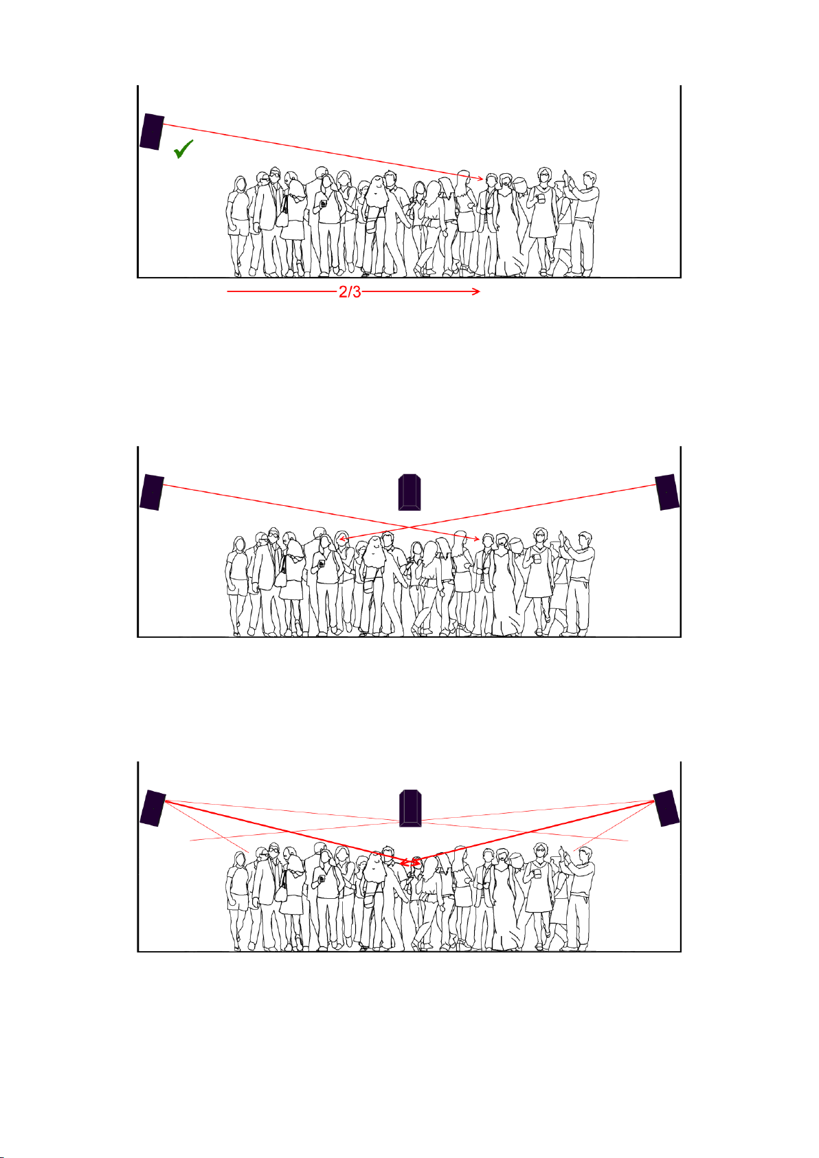
6.2 Placement ....................................................................................................................................................9
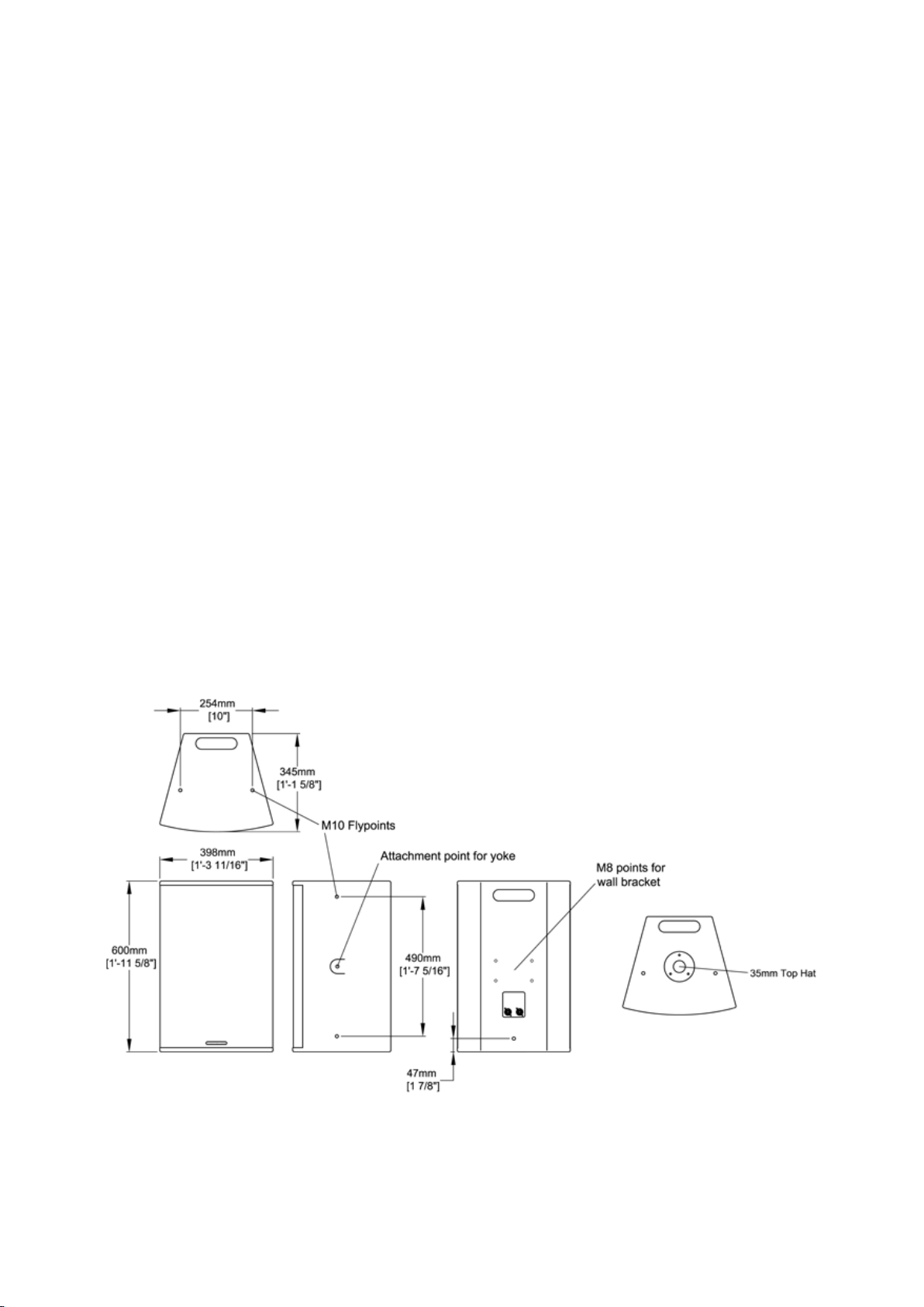
6.3 Wall mounting and yoke accessories .........................................................................................................15
7Connectors and pin-outs .......................................................................................................... 20
7.1 Speakon connector ....................................................................................................................................20
7.2 Loudspeaker polarity .................................................................................................................................21
8Loudspeaker cables.................................................................................................................. 23
8.1 Recommended cable types and lengths ....................................................................................................23
8.2 F1201 impedance.......................................................................................................................................23
9Amplifier considerations .......................................................................................................... 24
9.1 Recommended Funktion One power amplifiers ........................................................................................24
9.2 Suitable power ranges ...............................................................................................................................24
9.3 Simple system patches with external control ............................................................................................25
9.4 XO series loudspeaker management patches............................................................................................26
10 Combining with bass systems ................................................................................................... 28
10.1 Bass to mid-high alignment........................................................................................................................30
11 Limiters ................................................................................................................................... 34
11.1 XO series limiters with 32dB amplifiers .....................................................................................................35
11.2 Limiter settings vs amplifier gain ...............................................................................................................36
11.3 Limiter settings vs amplifier sensitivity ......................................................................................................37
Appendix A - Clipping ....................................................................................................................... 39
Appendix B –Gain structure ............................................................................................................. 42
Appendix C –Maximum spl .............................................................................................................. 51
www.funktion-one.com © Funktion One Research Limited 2013

3
1 Thank you
Thank you for purchasing a Funktion One F1201 system.
All Funktion One loudspeaker systems are designed and built in England. Our design philosophy is to
achieve outstanding sonic accuracy and efficiency through innovative acoustical design rather than
relying on headroom-robbing equalisation. This approach provides an audible sense of immediacy and
involvement reminiscent of the finest musical instruments.
We know that you’ll be eager to install your F1201 system and get it up and running immediately, but
reading this user guide will help you to achieve the best performance - just as Funktion One intended.
2 Receiving and unpacking
Please check that your shipment is complete and in good condition before signing for the delivery.
Palletised and wrapped/strapped multiple cartons should only be moved using a fork-lift truck
driven by a qualified forklift driver
Single cartons should be manually handled one at a time
All Funktion One products are tested and inspected thoroughly before being despatched.
Contents
Each F1201 carton should contain:
1 x F1201 complete with:
2 x M10 blanking screws fitted to the side yoke bushes
9 x M10 blanking screws fitted to the top, bottom, sides and rear mounting bushes
4 x M8 blanking screws fitted to the rear wall bracket mounting bushes
Quick start guide
Unpacking and inspecting
Inspect your shipment packaging and its contents for any signs of abuse or transit damage as soon as you
receive it.
Caution
Please be aware that the combination of smooth enclosure finishes and concentrated driver masses can
make even these loudspeakers surprisingly easy to drop.
Always unpack your systems on a softly covered work-top or on a carpeted floor to avoid accidental
damage.
www.funktion-one.com © Funktion One Research Limited 2013

4
Inform your dealer immediately if your shipment is incomplete or any of its contents are found to be
damaged or missing.
We suggest that you keep some of the original F1201 cartons in case you have to return a unit for repair
or replacement. Funktion One Research Limited and its distributors cannot be held liable for product
damaged through the use of non-approved packaging, shipping or handling methods.
3 Handling
If your F1201 systems are destined for an installation, ensure that they remain protected by their
packaging until the installation site is clean, secure and ready to accept them
Try to avoid placing F1201 systems face-down. Although fitted with tough, powder-coated steel
grilles, these grilles are optimised for unimpeded sound transmission and may suffer dents and
scratches from heavy handling
4 Introduction
The F1201 is the largest and most powerful of Funktion-One’s F-Series range of smaller loudspeakers.
Using the ever-popular combination of a 12” driver and 1” compression driver the F1201 offers
exceptional clarity and level over a wide range of frequencies. With Funktion One’s exceptional
enclosure tuning and driver optimisation, no processor or system equalisation is required; maximising
the fidelity, performance, natural simplicity and cost effectiveness of this product.
The trapezoid shape combined with an HF horn that can be easily rotated through 90° facilitates simple
horizontal or vertical deployment, as well as being part of horizontal and vertical arrays for larger
dispersion.
The F1201 works as a stand-alone PA or for use in small clubs and bars, and is ideally suited for use with
BR218, Infrabass 218 or F121 bass enclosures where low bass extension is needed.
4.1 Features
Compact enclosure with high output
Wide dispersion
Rotatable HF horn
Speakon connectors
12” and 1” drivers optimised to Funktion One specification.
Excellent Sensitivity
High passive crossover point to HF driver for low distortion
Trapezoid shape
Curved powder-coated mild steel grille
Integral pole mount
2 x M10 yoke mounting bushes
9 x M10 top, bottom, side and rear bushes
4 x M8 wall bracket bushes
www.funktion-one.com © Funktion One Research Limited 2013

5
4.2 Specifications
Driver complement: 12” cone driver
1” compression driver
Frequency response: 60Hz –19kHz
Dispersion: 90° horizontal x 40° vertical
Sensitivity: 100dB spl for 1W at 1m
AES power: 350W
Maximum calculated spl 125dB spl rms, 129dB spl peak
(SeeAppendix C)
Max long-term rms voltage: 52.9vrms
Max peak voltage: 105.8vpk
Recommended amp power: 350-1400W into 8ohms/700-2800W into 4ohm with suitable limiters
Nominal impedance: 8 ohms
Connectors: 2 x NL4 Speakon connectors
Fittings: Integral “top-hat” pole mount
2 x M10 yoke mounting bushes (one per side)
9 x M10 top, bottom, side and rear bushes
4 x M8 wall bracket bushes
Weight: 18kg (39lb)
Dimensions
Fig 4.2-1 F1201 dimensions (In millimetres and feet & inches)
www.funktion-one.com © Funktion One Research Limited 2013

6
5 Safety first
Funktion One wants you to continue to enjoy the world of music. Please take time to review the
following safety advice for your own wellbeing and for the wellbeing of those around you.
5.1 Mechanical safety
Qualified and experienced installers
Ensure that rigging and installation work is completed by fully qualified and experienced installation
personnel
Your F1201 loudspeaker system comes complete with an M10 bush on each side for yoke mounting, nine
M10 bushes on the top, bottom, sides and rear, four M8 wall bracket bushes and a “top hat” socket on
the bottom for pole mounting.
For safety, and ease of installation:
Free standing loudspeakers
Free-standing loudspeakers can vibrate and move when driven hard. Always place free-standing
loudspeakers on resilient mats and secure loudspeakers so that they cannot fall and cause injury
Brackets and yokes
Use only Funktion One-recommended brackets and yokes with your F1201. See section 6.3
Do not mount more than one F1201 from a single yoke or bracket
Always attach a separate safety wire rope to each yoke’s safety point
Follow the mounting advice. See section 6.3
Pole mounting
Make sure your pole mount is compatible with the F1201’s 35mm pole socket and is a snug fit.
Always check the stand manufacturer’s specifications
Make sure that the pole mount stand will support the weight of the loudspeaker. Again, check
the stand manufacturer’s specifications
If using more than one F1201 on the same stand, check that the stand is designed for multiple
loudspeakers
Always place your stand on a level surface and check that its legs are fully extended and locked
Make sure that stands do not present a trip hazard
Use a load spreader under each stand foot if the ground is soft
Fully secure outdoor stands so that they cannot fall over in high winds. We suggest four equally
spaced stainless steel wire guy ropes per loudspeaker
Make sure that cables do not present a trip hazard which could cause injury or pull the speaker
over
Observe similar precautions when combining full-range loudspeakers with subwoofers.
www.funktion-one.com © Funktion One Research Limited 2013

7
5.2 Electrical and fire safety
Qualified and experienced technicians
Funktion One F1201 loudspeakers are very efficient and require relatively low voltage levels. However, in
line with any other electrically powered device, a few precautions are worth noting. If in doubt, seek help
from a professional system technician.
Cabling
Use only Funktion One recommended loudspeaker connectors wired so that the cable
conductors are fully shrouded
Use the appropriate cable conductor gauge. See section 8.
Ensure that your cables are in good condition and free from damage
Ensure that there are no loose conductor strands to short out and create a fire hazard
If you re-use older cables, strip them back a little, wherever possible, to expose clean conductor
ends that are free from corrosion
Use fire retardant or low emission cables where these have been specified by the contract or by
local safety regulations
Amplification
We suggest electronically limiting maximum amplifier power of 350W average/ 700W peak
Remember that heavily clipped signals can double a power amplifier’s output. See appendix A.
If heavily clipped signals are expected due to equipment with inadequate headroom in the signal
path, inexperienced operators etc., set rms and peak output limiter thresholds 3dB below the
loudspeaker’s AES ratings. See section 11.
General
There are no user-serviceable parts inside your F1201 system. Do not dismantle the unit
F1201’s are not designed for use in damp conditions and should not be exposed to water
5.3 Hearing safety
Enjoy your system responsibly
Funktion One loudspeaker systems are designed to provide extensive audience coverage at low
distortion and are capable of producing very high near-field sound pressure levels.
The richness and impact of a powerful sound system can be great fun and very exhilarating; but please
enjoy your Funktion One system responsibly by following the advice below...
www.funktion-one.com © Funktion One Research Limited 2013

8
Don’t place your ears too close to high power loudspeaker systems. Erroneous patching or un-
muting could generate unexpected and damaging sound pressure levels during set-up.
Don’t place high power loudspeakers too close to audience members. Individual audience
members should not be exposed to levels significantly greater than the sound operating area
Wearing ear plugs may be a sensible precaution during system set-ups but remember that you
have a duty of care towards the venue staff and the audience. Mix engineers, DJs, subcontractors
and venue management should avoid making not make system level and equalisation decisions
whilst wearing ear plugs as this could overexpose venue staff or the public in the vicinity
Hearing loss is cumulative and can result from long-term exposure to sound pressure levels as
low as 85dBA. Installers should consider long-term staff exposure when making high power
loudspeaker placement and aiming decisions. Check the relevant noise exposure/noise at work
regulations and comply with them. If in doubt, seek expert advice.
6 Coverage
Your F1201 loudspeaker system has been designed to provide excellent performance without resorting
to complex positional or spacing requirements, but it’s worth spending a couple of minutes reading
through the following sections on horizontal and vertical coverage, placement and mounting accessories
to ensure you get the best performance possible at all times.
6.1 Vertical and horizontal responses
The horizontal and vertical response plots show the on-axis (upper) response vs the off-axis (lower)
response.
Fig 6.1-1 On-axis vs 45° horizontal off-axis response
The F1201 has been designed to work well as a stand-alone system without off-axis room colouration.
Multiple F1201s may be splayed 30-45° axis-to-axis horizontally or 15-22° axis-to-axis vertically for wide
coverage applications. The lower splay angle gives extra summation between the cabinets in each case.
www.funktion-one.com © Funktion One Research Limited 2013

9
Fig 6.1-2 On-axis vs 22° vertical off-axis response
6.2 Placement
Vertical aiming
Fig 6.2-1 Poor vertical aiming
Avoid aiming your F1201 straight over the audience’s heads as this will increase room effects causing
poor impact and intelligibility.
Even if the room has good acoustical properties, your audience will enjoy far better sound quality if the
system is aiming towards them.
Mounting your F1201 systems 2.8 –3.3m above the floor and aiming them towards head height about
2/3rds across the audience will provide smooth coverage without over-exciting the room.
See next page…
www.funktion-one.com © Funktion One Research Limited 2013

10
Fig 6.2-2 Improved vertical aiming
Audience members near the F1201s will benefit from their smooth vertical mid-high characteristics.
These listeners will still enjoy the F1201s’ rich, broadband sound, but the subtle off-axis roll-off will
compensate for proximity.
Multiple loudspeaker systems
Fig 6.2-3 Aiming multiple F1201s for concentrated coverage
Multiple F1201s may be used to concentrate coverage into a specific area. This will provide audience
members with a pleasant, enveloping experience.
Minimising difficult room effects
Fig 6.2-4 Raising and tilting F1201s for more concentrated central coverage in difficult acoustics
www.funktion-one.com © Funktion One Research Limited 2013

11
Difficult room effects can be minimised by aiming your F1201s towards head height at the centre of the
audience area. This ensures that coverage is concentrated onto the main audience area and away from
the walls.
The strong central summation combined with the smooth off-axis performance around the edges will
provide even coverage with minimal overspill.
Horizontal aiming
Stereo set-ups
Fig 6.2-5 Poor horizontal aiming
Avoid aiming your F1201 straight out as this can increase side wall effects and will cause coverage gaps in
between the loudspeakers.
Fig 6.2-6 Improved horizontal aiming
Even if the room has good acoustical properties, your audience will enjoy far better sound quality if the
system is toed in towards them rather than reflecting off the side walls.
The classic 60° stereo set-up (see next page) was devised for personal monitoring or home listening over
a relatively small listening area. Achieving good stereo imaging for larger spaces can be a challenge due
to the much larger left-right propagation times involved.
www.funktion-one.com © Funktion One Research Limited 2013

12
The 60° angle is not critical. The appropriate set-up for your particular application will be an intelligent
compromise between stereo imaging and coverage without too much spill onto side walls.
The best way to ensure the widest possible stereo listening area is to aim your left and right F1201
systems, both horizontally and vertically, so that their on-axis lines cross over at ear height at
approximately 2/3 the distance to the rear of the audience.
Fig 6.2-7 Classic stereo set-up
2/3rds rule for audio-visual applications
If your loudspeaker system is providing front left and right sound for a specific video screen, place your
loudspeakers so that their high frequency units are approximately 2/3rds up the screen and then tilt them
so that they aim approximately 2/3rds across the audience area.
The above aiming rules still apply, of course.
www.funktion-one.com © Funktion One Research Limited 2013

13
Multiple loudspeaker systems
Where multiple loudspeakers are to be used to concentrate coverage into a specific area, your F1201’s
90° horizontal coverage allows simple four-corner set-ups for foreground music coverage.
Fig 6.2-8 4-speaker set-up
Generally speaking, every time you double the number of loudspeakers at equal distances from you,
you’ll increase sound pressure level by between 3 and 6dB. The exact figure will depend on the
programme material.
If you’re at the central “sweet spot” of a stereo loudspeaker system, centrally-panned signals –e.g.
vocals or bass –will sum up to 6dB, whereas stereo signals will sum up to 3dB.
In the 4-speaker example, this summation effect will be doubled and concentrated towards the centre of
the audience area. As audience members move towards the centre –away from the loudspeakers - this
4-speaker summation will partially compensate for distance. This leads to very smooth level coverage.
If the architecture allows, always try to keep your loudspeaker positions symmetrical in the room.
Large-scale distributed loudspeaker systems
If wide coverage is more important than stereo or multi-channel operation (e.g. for a conference venue
or large lecture theatre), a mono, distributed system may be a better option.
The example (overleaf) uses 12 F1201s to cover a 40m wide, 180°, fan-shaped audience.
www.funktion-one.com © Funktion One Research Limited 2013

14
Fig 6.2-9 Large-scale distributed system - horizontal
Remember that, in circular or fan-shaped rooms, the second (delay) ring covers a radially expanding
audience area so more loudspeakers are required to maintain smooth coverage.
In this example the platform F1201s are placed every 45˚ and the second ring F1201s are placed every
30°.
Vertical aiming and time alignment
Fig 6.2-10 Distributed system –vertical
Aiming
Design the system for a smooth coverage “crossover”, at ear level, between main and delay areas. But
avoid excessive overlap as this will cause multiple arrivals and could reduce intelligibility.
Alignment procedure
Adjust the Delay F1201 spl level for a smooth, equal level overlap area
Add the appropriate electronic delay* to the Delay F1201 signal
* This additional delay can be calculated if you know the relevant distances.
The required delay, in milliseconds, will be:
Metric: (Distance in metres from Main F1201 –Distance in metres from Delay F1201) x 2.91
Imperial: (Distance in feet from Main F1201 –Distance in feet from Delay F1201) x 0.887
(Hint: If you don’t have a calculator, the multipliers may be rounded to 3.0 for metric or 0.9 for imperial)
Real-world testing
Make final level adjustments in a real-world situation - with lots of audience absorption, background
noise and chatter. This will highlight any coverage or intelligibility weak spots that may need correcting.
www.funktion-one.com © Funktion One Research Limited 2013

15
6.3 Wall mounting and yoke accessories
Wall bracket
Fig 6.3-1 WME-100 wall mounting bracket (all dimensions in mm)
The optional WME-100 wall mounting bracket allows your F1201 to be mounted on a wall and aimed
accurately.
1st and 2nd fit
The wall mounting plate may be removed and sent to site for pre-installation if required.
Fig 6.3-2 Wall mounting plate removed for fitting on site Speaker mounting plate fitted to F1201
www.funktion-one.com © Funktion One Research Limited 2013

16
Always discuss your required wall mounting plate positions, the weight of your loudspeaker
and wall anchorage methods with an expert builder or the architect to make sure you comply with the
relevant building and safety regulations
The speaker mounting plate is attached to your F1201 with the M8 hex-head
bolts, flat washers and spring washers provided.
The hex-head bolts, flat washers and spring washers replace the countersunk
blanking bolts at the rear of your F1201. The countersunk bolts should be
retained for future use.
Tighten the hex-head bolts so that the spring-washers are fully compressed –
(example on right).
Fig 6.3-3
Remember to replace the rear bolts
Do not run the system with its rear bolts missing as this will detune the cabinet and cause air-flow noise.
If you remove the wall bracket, always refit the original countersunk blanking bolts.
Reassemble the wall bracket system on site using the flat washer and the horizontal locking nut supplied
before make final swivel and tilt adjustments.
Swivel & tilt
Fig 6.3-4 Horizontal swivel Fig 6.3-5 Vertical tilt
www.funktion-one.com © Funktion One Research Limited 2013

17
Horizontal swivel
Loosen the horizontal locking nut (See Fig 6.3-4 above) to swivel the main assembly to the required
position.
Retighten the horizontal locking nut once you’re happy with the position.
Vertical tilt
Loosen the vertical locking nut to allow the loudspeaker plate to be tilted to the required position using
the tilt screw (See Fig 6.3-5 above).
If the loudspeaker is already attached to the speaker mounting plate, this is much easier to do if you get
a helper to lift the loudspeaker gently whilst you make the adjustment.
Retighten the vertical locking nut once you are happy with the vertical positioning. Then give the tilt
screw a final tweak just to make sure it’s still tight.
(Side view) (View from above)
Fig 6.3-6 Maximum tilt and swivel angles (F1201 mounted vertically)
(Side view) (View from above)
Fig 6.3-7 Maximum tilt and swivel angles (F1201 mounted horizontally)
www.funktion-one.com © Funktion One Research Limited 2013

18
Yoke kits
YF1201 vertical yoke
The optional YF1201-K1 vertical yoke kit allows you to fly your F1201 from a truss or 51mm barrel via a
standard half-coupler using the main fixing hole. The yoke also has a 7mm safety wire attachment hole.
The F1201 has integral M10 side bushes so that the yoke may be fitted using M10 hex-head bolts and flat
washers for fixed installations. The YF1201 vertical yoke kit allows for a full 360°enclosure rotation
Fig 6.3-8 YF1201-K2 vertical yoke kit with captive bolts and clamping lever
(YF1201-K1 vertical yoke kit –not shown - has captive bolts and no clamping lever)
See top of next page for dimensional details.
Remember to replace the side bolts
Do not run the system with its side bolts missing as this will detune the cabinet and cause air-flow noise.
If you remove the yoke, always refit the original countersunk blanking bolts.
Stand-top adaptor
Your F1201 comes complete with a fixed 35mm “top hat” pole socket for
vertical mounting.
However, where a tilt is required, the YF1201-K1 or K2 yoke kit can be fitted
with an optional stand-top adaptor –see left illustration on Fig 6.3-9 above.
Both 32mm and 35mm stand-top adaptor are available. These bolt through
the yoke’s main fixing hole with an M12 bolt and is clamped to the stand
pole using a wing-bolt. M12 stand-top adaptor
www.funktion-one.com © Funktion One Research Limited 2013

19
Fig 6.3-9 YF1201 vertical yoke dimensions (millimetres and feet & inches)
YH1201 horizontal yoke
A horizontal yoke kit is also available. It comes complete with pivot plates that bolt to the F1201’s “top”
and “bottom” M10 mounting bushes. This yoke also has a 7mm safety point and allows for a full 360°
enclosure rotation.
Fig 6.3-10 YH1201-K1 horizontal yoke kit with hex nuts and washers
(The YH1201-K2 horizontal yoke kit –not shown - has clamping lever and washers)
www.funktion-one.com © Funktion One Research Limited 2013

20
7 Connectors and pin-outs
7.1 Speakon connector
The two NL4s are internally connected. One is used for the input. The other is used as an output for
additional (parallel-connected) F1201s.
Note that the F1201 uses only two of the four available NL4 pins. Suitable cable connectors include the
industry standard Speakon NL4FC and the Speakon NL2FC (compatible with NL4 chassis connectors for 2-
pin use).
(Original image courtesy Neutrik)
Fig 7.1-1 Your F1201’s rear NL4 connectors will accept either NL2 or NL4 connector types
The following illustrations show the cable connector pin views looking towards the rear of the
loudspeaker - as they would be seen if the cable plugs were plugged into the F1201 with their covers
removed.
Fig 7.1-2 NL2FC (cable grab open) Fig 7.1-3 NL4FC pin-out
(Original image courtesy Neutrik)
Use 1+ for F1201 +ve, 1- for F1201 –ve.
For further information on the Speakon connector series, see the Speakon System assembly instruction
pdf available from www.neutrik.com.
www.funktion-one.com © Funktion One Research Limited 2013
Table of contents
Other Funktion-one Speakers manuals
Popular Speakers manuals by other brands

Bang & Olufsen
Bang & Olufsen Beoplay A9 3rd Generation user guide

Whelen Engineering Company
Whelen Engineering Company WS100TCH Assembly

thomann
thomann FunGeneration Speaker ToGo BT user manual

Ikon
Ikon CM 5000.1 user manual

LG
LG FJ5 Simple manual

Wharfedale Pro
Wharfedale Pro Crystal 4 Series user manual