Funktion-one SB8A User manual

A1-00001-10
Fault
Limit
Power Bass Level
0
-+
P
B
ol
a
a
s
r
s
ity
-+
In
L
p
ef
u
t
t
R
In
i
p
g
u
h
t
t
U
1
B
n
/
b
a
4
X
l
a
a
’’
l
L
n
a
J
R
c
n
a
e
c
c
d
e
k
dU
1
B
n
/
b
a
4
X
l
a
a
’’
l
L
n
a
J
R
c
n
a
e
c
c
d
e
k
d
O
L
u
e
tp
ft
ut O
R
u
ig
tp
h
u
t
t
Maximu
1
m
50
o
W
utp
i
u
n
t
to
pe
4
r
Ω
channel
ty
R
p
T
w
e
e
3
p
i
A
t
a
l
h
a
n
L
c
d
s
2
e
a
r
5
m
a
fu
0
t
e
i
s
V
n
e
g:
1
5
0
0
0
-
-
6
2
0
4
H
0
z
V
120W
wi
S
th
p
in
ar
h
e
o
f
u
u
s
s
i
e
ng
RISK O
C
F
A
EL
U
EC
T
T
IO
RIC
N
SHOCK
N
D
D
D
TH
o
O
O
O
I
u
S
N
N
N
s
E
e
O
O
O
r
Q
T
T
T
s
U
e
U
U
E
r
I
X
S
S
v
P
i
P
c
E
E
M
e
O
I
A
E
a
N
S
b
B
N
l
E
T
e
O
T
R
T
p
V
M
O
O
a
E
U
r
P
t
R
2
s
S
IC
0
A
D
T
in
0
I
A
N
s
O
B
0
L
id
E
O
M
N
C
e
E
R
E
O
L
A
I
T
M
M
T
R
R
A
O
T
O
E
T
H
S
I
P
S
E
E
E
T
A
R
D
N
U
L
E
T
R
G
IT
E
U
IO
D
N
E
S
Referservicing to qualied personnel
RISQUE
A
D
T
U
T
C
E
HO
N
C
T
E
IO
LE
N
CTRIQUE
P
I
S
N
N
C
l
r
n
E
E
E
E
iè
'y
U
T
P
P
re
a
L
A
A
E
E
d
p
S
S
Q
M
e
a
U
U
E
s
s
E
X
I
T
e
d
P
N
I
P
e
L
r
M
T
é
O
I
p
S
f
E
U
é
i
S
è
E
N
r
T
c
e
E
R
I
T
e
r
L
R
s
E
à
I
D
S
A
N
r
u
O
E
é
n
L
p
R
R
IT
A
a
p
E
S
r
e
E
a
P
G
N
r
O
T
b
s
L
E
R
I
l
o
U
O
U
e
n
E
s
P
I
S
N
n
E
A
p
R
e
S
U
S
O
a
l
E
r
d
N
C
U
L
O
l
e
'
E
u
I
L
E
A
U
m
t
I
i
A
M
l
V
A
i
a
L
s
L
’
A
R
i
T
a
H
n
L
T
t
I
I
t
A
T
e
U
R
e
IQ
U
u
n
M
T
r
a
U
D
E
à
I
n
D
E
E
R
c
l’
S
I
e
R
i
D
T
n
E
E
t
q
T
E
é
u
R
r
2
i
a
e
O
0
li
u
fi
0
P
r
é
0
IC
M
A
E
LE
TR
S
ES
Ho
F
y
u
le
n
,
k
H
+
S
ti
M
o
o
4
u
n
r
4
r
a
s
r
d
e
O
h
(
y
e
0
a
n
,
m
)
i
e
R
1
n
3
H
R
R
E
0
o
e
5
n
6
a
s
g
4
e
d
l
7
a
P
a
,
1
n
r
B
S
c
d
2
e
,
h
8
b
U
a
2
L
y
r
K
e
i
0
m
G
ite
re
d
en,
www.funktion-one.com
SB8A /SB10A USER GUIDE

TABLE OF CONTENTS
1 Safety and regulations 6
1.1 Important safety instructions 6
1.2 Important safeguards 6
1.3 WEEE Directive 6
1.4 EC Declaration of Conformity 7
1.5 Electrical considerations 7
1.6 Mechanical & thermal 7
1.6 Volume warning 7
1.7 Safety symbols 7
2 Warranty 8
2.1 Funktion One Limited Warranty 8
2.2 Obtaining service 8
3 Introdu tion 9
3.1 Welcome 9
3.2 On Delivery 9
3.3 Unboxing 10
4 Spe ifi ations 11
4.1 Loudspeakers 11
4.2 A1 Amplier 12
5 Operation 13
5.1 Amplier front panel 13
5.2 Amplier indications 14
6 Conne tions 15
6.1 Input Connections 15
6.2 Balanced & Unbalanced Interconnections 15
6.3 Identifying audio connectors 15
6.4 Identifying the correct cable 16
6.5 Output Connections 17
6.6 Recommended loudspeakers 17
6.7 Loudspeaker cable considerations 17
6.8 Connectors 18
6.9 Maximum Loads 18
6.10 F5 amplier load 19
6.11 F81.2 amplier load 19
SB8A/SB10A User Guide Version 1.1
© Funktion-One-Research Limited 2021
Keep this guide in a safe place so it’s available for future reference.
This guide is subject to change without notice. We recommend you to regularly
check the Funktion-One website for the latest version of this document.
Funktion-One Research Limited
Hoyle, Horsham Road, Beare Green,
Dorking Surrey, RH5 4PS
Phone: +44 (0)1306 712820
Mail: mail@funktion-one.com
www.funktion-one.com
7 Analogue signal pro essing 20
7.1 Signal path 20
7.2 Cross over lters 20
8 Setup 21
8.1 Loudspeaker placement 21
9 Timing optimisation 22
9.1 Position tuning 22
9.2 Using the polarity switch 23
9.3 Room acoustics 24
10 Appendix 25
10.1 Digital audio les 25
10.2 Room modes 26
10.3 Sound waves 27
10.4 Useful dB Increments 28
10.5 Recommended further reading 29

SB 8A /SB10A U SER GUIDE
1 2
WARNING: THIS EQUIPMENT MUST BE EARTHED
(CLASS I APPLIANCE)
Risk of re: Do not expose to rain or moisture.
No user serviceable parts inside – refer servicing to qualied personnel.
Only to be used at altitude below 2000 metres.
Only to be used in non-tropical climate regions.
For indoor use only.
Do not use this amplier if the electrical power cable is frayed or broken.
No naked ame sources such as lit candles should be placed on the equipment.
This device must be powered exclusively by earth connected mains sockets in
electrical networks compliant with IEC 364 or similar.
This unit has been engineered and manufactured to ensure your personal safety.
IMPROPER USE CAN RESULT IN POTENTIAL ELECTRICAL SHOCK OR
FIRE HAZARD
In order not to defeat the safeguards incorporated into this product, observe the
following basic rules for its installation, use and service. Please read “Important
Safeguards” listed below carefully before use.
1.1 Important safety instru tions
1.2 Important safeguards
1.3 WEEE Dire tive
Read these instructions.
Keep these instructions.
Heed all warnings.
Follow all instructions.
Do not use this equipment near water.
Disconnect the AC mains source before attempting to clean any part of the
amplier.
Clean with a damp cloth.
Do not block any ventilation openings. Install in accordance with the manufacturer’s
instructions.
Do not install near any heat sources such as radiators, stoves, or other apparatus
that produce heat.
Protect the power cord from being walked on or pinched particularly at power
outlets and the point where they exit from the apparatus.
Only use attachments/accessories specied by the manufacturer.
Use only with the trolley, stand, tripod, bracket, or table specied by the
manufacturer, or sold with the apparatus. When a trolley is used, use caution when
moving the trolley/apparatus combination to avoid injury.
Unplug this apparatus during lightning storms or when unused for long periods of
time.
Refer all servicing to qualied service personnel. Servicing is required when the
apparatus has been damaged in any way, such as power-supply cord or plug is
damaged, liquid has been spilled or objects have fallen into the apparatus, the
apparatus has been exposed to rain or moisture, does not operate normally, or has
been dropped.
The apparatus shall be connected to a MAINS socket outlet with a protective
earthing connection.
THE MANUFACTURER CANNOT BE HELD RESPONSIBLE FOR DAMAGES
CAUSED TO PERSONS, THINGS OR DATA DUE TO AN IMPROPER OR
MISSING GROUND CONNECTION.
The Waste Electrical and Electronic Equipment Directive (WEEE Directive) aims
to minimise the impact of electrical and electronic goods on the environment.
Funktion-One Research Ltd. comply with the Directive 2012/19/EU.
Funktion-One products are designed for longevity and repairability, we hope they
provide many decades of enjoyment and useful operation. In the unlikely event that
you need to dispose of your Funktion-One product, all of our products are marked
with the WEEE symbol; this indicates that this product must NOT be disposed
with other waste. Instead it is the user’s responsibility to dispose of their unwanted
Funktion-One electrical and electronic equipment by returning it to Funktion-One
Research Ltd. for recycling and reprocessing.
For more information about where you can send your waste equipment for
recycling, please contact Funktion-One Research Ltd. or your local distributor.
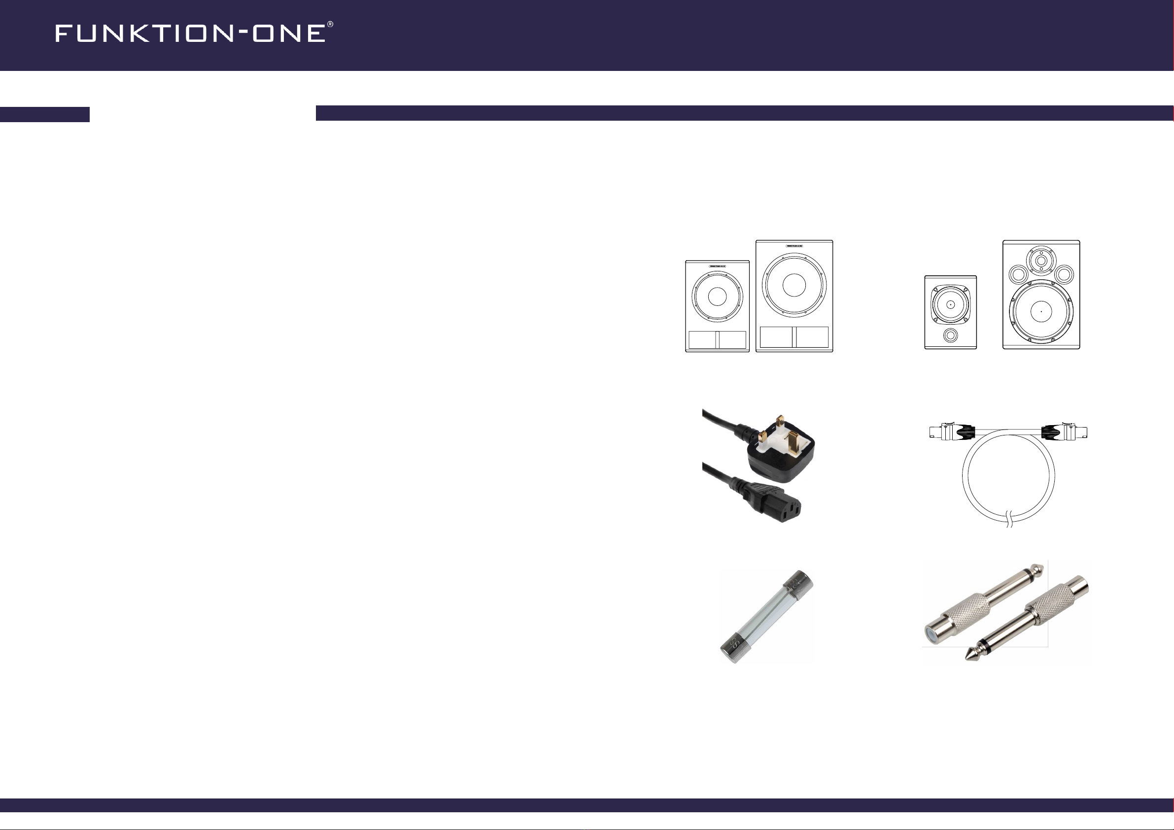
The SB8A/SB10A contains a universal power factor corrected (PFC) switched-
mode power supply (SMPS) which operates on a voltage range of 100-240V AC,
50-60Hz.
The SB8A/SB10A contains hazardous internal voltages. Do not open the amplier
enclosure – risk of electric shock.
No user serviceable parts inside. Refer servicing to qualied personnel.
The SB8A/SB10A is a Class I appliance and MUST be connected with a three-
wire cable to a mains outlet with a safety earth connection.
THE EARTH WIRE SHOULD NOT BE DISCONNECTED UNDER ANY
CIRCUMSTANCE.
IEC C13 mains cables are readily available worldwide.
For reference, the mains wiring in EU countries is:
Earth: Green and Yellow
Neutral: Blue
Live: Brown
The mains inlet contains a user-replaceable fuse.
For continued protection against re, only replace the fuse with the same type and
rating: T3.15AL 250V (5x20mm glass)
1.5 Ele tri al onsiderations
1.6 Me hani al & thermal
NEVER under any circumstance replace the fuse with a higher rating. Risk of re
and damage to the equipment.
Repeated fuse blowing indicates a fault and the amplier must be returned to
Funktion-One for service.
ENSURE THERE IS ADEQUATE VENTILATION
The amplier enclosure is convection cooled therefore care must be taken to
ensure that sufcient volumes of air can ow across and through the amplier.
This is usually accomplished by ensuring vents are not blocked and at least
100mm (4’’) of free space from the rear panel of the amplier module, and 150mm
(6”) above the cabinet.
If airow is impeded, the amplier will overheat and enter thermal protect mode
(fault LED solid red).
1
SAFETY AND REGULATIONS
1.7 Safety symbols
The triangle with the lightning bolt is used to alert the
user to risk of electric shock.
The triangle with the exclamation point is used to alert
the user to important operating or maintenance
instructions,
For United States of America
Do not defeat the safety purpose of the polarized or grounding-type plug.
A polarized plug has two blades with one wider than the other. A grounding type
plug has two blades and a third grounding prong. The wide blade or the third
prong are provided for your safety. If the provided plug does not t into your
outlet, consult an electrician for replacement of the obsolete outlet.
1.6 Volume warning
The SB8A/SB10A is capable of producing high sound levels that can damage
your hearing over time. Care should be taken to manage your noise exposure
levels.
4Ωloads on the satellite outputs will signicantly increase the thermal dissipation,
and forced air cooling may be required to sustain full output in high ambient
temperatures.
The amplier is designed to be permanently xed inside the loudspeaker cabinet
and should not be operated outside of the cabinet.

SB 8A /SB10A U SER GUIDE
3 4
2
WARRANTY
Funktion-One Research Limited shall as soon as reasonably practicable repair or replace any faulty products
or components during the period of 24 months (limited to 12 months for products sold as water resistant) from
the date of delivery where such defects occur under correct and proper usage save that this warranty shall not
apply where any product has been changed, modied, abused, installed or operated incorrectly or interfered
with in any way. Any products being returned the factory or service center must be shipped prepaid.
The Seller shall have no further liability to the Purchaser.
This warranty relates only to Funktion-One equipment and specically excludes any works carried out by an
installation company which relate to the installation of the system into the venue.
2.1 Funktion One Limited Warranty
If your Funktion-One product require service contact your local distributor to raise a claim, a distributor list can
be found at www.funktion-one.com.
Should it not be possible to resolve your issue remotely you may have to send your product to a service center.
If this is the case package the loudspeaker in its original packaging and return it to the service center stipulated
by your distributor or sales outlet. Ensure the loudspeaker is well packed and that following information is
provided inside the box;
2.2 Obtaining servi e
• Name
• Address
• Contact email
• Contact phone number
• Brief description of the fault
1.7 UKCA De laration of Conformity
This declaration applies to the self powered loudspeakers
manufactured by Funktion-One research Ltd. listed below:
SB8A
In accordance with the following
Low Voltage Directive 2014/35/EU.
Electromagnetic Compatibility Directive 2014/30/EU.
Restriction of Hazardous Substances (RoHS) Directive 2011/65/EU.
We declare that the listed products are in the conformity with the
applicable requirements for the following documents:
LVD:
EN62368-1:2020+A11:2020
EMC:
EN 55032:2015+A1:2020
EN 550305:2017+A11:2020
RoHS:
EN 63000:2018
Tony Andrews, Director,
Funktion-One Research Limited.
Issued on the 20th of January 2021
Hoyle, Horsham Road, Beare Green, Dorking, Surrey
This declaration applies to the self powered loudspeakers
manufactured by Funktion-One research Ltd. listed below:
SB8A
In accordance with the following
Electrical Equipment (Safety) Regulations 2016.
Electromagnetic Compatibility Regulatioins 2016.
The Restriction of the Use of Certain Hazardous Substances in
Electrical and Electronic Equipment Regulations 2012.
We declare that the listed products are in the conformity with the
applicable requirements for the following documents:
Electrical Equipment Safety:
EN62368-1:2020+A11:2020
Electromagnetic Compatibility
EN 55032:2015+A1:2020
EN 550305:2017+A11:2020
EN 61000-4-16:2016
RoHS:
EN 63000:2018

SB 8A /SB10A U SER GUIDE
5 6
Thank you for purchasing this Funktion-One system.
This user guide includes the information you will need to congure the system correctly, ensuring you enjoy its
full sonic capabilities.
You are now a member of the global Funktion-One family. We hope this sound system brings you many years
of listening enjoyment.
INTRODUCTION
Before signing for your delivery you should:
• Carry out a full visual inspection of the parcel looking for signs of abuse, contamination or transit
damage.
• Conrm that all invoiced items are with the consignment.
• If for any reason the consignment is incomplete or its contents are found to be damaged inform the
shipping company/delivery driver and contact your Funktion-One dealer.
3.2 On Delivery
3.1 Wel ome 3.3 Unboxing
1 x Mains cable, IEC C13 to UK/EU/US plug 2 x 3m Speakon NL2-NL2 speaker cables
2 x Phono (RCA) to 1/4’’ jack adapters1 X Spare T3.15AL 250V fuse
The SB8A and SB10A pack contains almost everything you need to get going. You should nd the following
hardware within the system packaging:
1 x SB8A or SB10A subwoofer **
**Depending on your selected system.
2 x F5 or 2 x F81.2 loudspeaker **
Not included: Audio Source (DJ mixer, DAC, Preamplier etc.)
Audio signal cables.
Speaker stand / wall brackets.
3

SB 8A /SB10A U SER GUIDE
7 8
4
SPECIFICATIONS
4.1 Loudspeakers
Sensitivity (1W at 1m) 97dB at 4V 98dB at 2.8V
Nominal impedance 16Ω8Ω
Power (AES) 30W 100W
Frequency response ±3dB 160-13KHz 95-19kHz
Weight 2.7kg (5.09lbs) 5kg (46.3lbs)
238mm
(9 3/8’’’’)
168mm
(6 5/8’’’’) 163mm
(6 7/16’’’’)
353mm
(1’-1 7/8’’’’)
250mm
(9 13/16’’’’) 225mm
(8 7/8’’’’)
Sensitivity (1W at 1m) 96dB at 2.8V 98dB at 2.8V
Nominal impedance 8Ω8Ω
Power (AES) 250W 300W
Frequency response ±3dB 50-250Hz 48-250Hz
Weight (With amplier) 15kg (33.07lbs) 21kg (46.3lbs)
274mm
(10 13/16’’’’)
440mm
(1’-5 5/16’’’’)
393mm
(1’-3 1/12’’’’)
SB8A SB10A
480mm
(1’-6 7/8’’’’)
330mm
(1’ 1’’)
510mm
(1’-8 1/16’’’’)
F5 F81.2
4.2 A1 Amplifier
Channels 3
LF output power (8Ω)300W
Satellite output power (8Ω)2 x 75W
Frequency response (LF) SB8A: 50-150Hz / SB10A: 40-140Hz
Frequency response (Satellite) SB8A: 150-20kHz / SB10A: 140Hz-20kHz
THD+N(%) 0.005% - 0.5%
Input impedance (Balanced XLR) 22kΩ
Input impedance (Unbalanced TRS Jack) 4.7kΩ
Max input level (Balanced XLR) +11dBu RMS / +23dBu peak**
Max input level (Unbalanced TRS Jack) -2dBu RMS / +10dBu peak**
Power supply Universal regulated SMPS with PFC
Power requirements 100-240V AC 30-230W
Connections IEC power inlet, XLR/TRS combo inputs, Speakon NL4 outputs
**With bass level control at 0

SB 8A /SB10A U SER GUIDE
9 10
5
OPERATION
A1-00001-10
Fault
Limit
Power Bass Level
0
-+Bass
Polarity
-+
Left
Input
Right
Input
XLR
Balanced
1/4’’ Jack
Unbalanced
XLR
Balanced
1/4’’ Jack
Unbalanced
Left
Output Right
Output
Maximum output per channel
150W into 4Ω
Replace fuse
with same
type and rating:
T3AL 250V
100-240V
50-60Hz
120W
Spare fuse
within housing
CAUTION
RISK OF E LECTRIC SHOCK
DO NOT OPEN
THIS EQUIPMENT MUST BE EARTHED
DO NOT EXPOSE TO RAIN OR MOISTURE
DO NOT USEI N TROPICAL CLIMATE REGIONS
DO NOT USEABOVE 2000 METRES ALTITUDE
No user serviceable parts inside
Refer servicing to qualied personnel
ATTENTION
RISQUE DU CHOC ELECTRIQUE
NE PAS OUVRIR
CET EQUIPMENT DOIT ETRE RELIE A LA TERRE
NE PAS EXPOSER A LA PLUIE OU A L’HUMIDITE
NE PAS UTILISER EN REGIONS CLIMATIQUES TROPICALES
SEULEMENT UTILISER SOUS UNE ALTITUDE DE 2000 METRES
Il n'y a pas de pièces réparables par l'utilisateurà l’intérieur
Prière de se référer à un personnel de maintenance qualié
Made in England by
Funktion One Research Limited
Hoyle, Horsham Road, Beare Green,
Surrey, RH5 4PS, UK
+44 (0)1306 712820
www.funktion-one.com
IEC A/C mains input 100-240V AC, 50-60Hz, 30-230W
Amplier status indicators
Red - Fault
Amber - Limiter engaged
Green - Power
Bass level adjustment knob
Bass polarity switch (+/-)
Left speaker and right speaker outputs (Speakon NL4)
Left and right audio input (¼’’Jack / XLR Combi connector)
The SB8 amplier has been carefully designed to meet Funktion-One’s exacting standards of audio delity and
reliability. The shock mounted module houses an analogue signal processing board with active crossover and
limiter, a three channel pulse width modulation (Class D) amplier and universal switch mode power supply.
5.1 Amplifier front panel
Power switch
Fuse holder (T3.15AL 250V)
Power LED off
Amplier Off
Connect to a power source and turn on switch
If still no power check the T3.15AL 250V fuse located in the
holder**
Power LED on Amplier on
Limit LED off Amplier operating correctly
Limit LED on or
Flashing
Amplier is limiting, reduce input level
Continuous limiting may damage the loudspeaker
Fault LED Off Amplier operating correctly
Fault LED on
Amplier fault
The amplier will automatically recover from temporary fault conditions
If the indicator remains lit contact your local Funktion- ne Dealer
The LEDs on the amplier indicate the ampliers status.
When switching the unit on, the green power LED and red fault LED will illuminate during the ampliers self
test phase. After 3 seconds the red fault LED will extinguish, the amplier is now ready for use.
5.2 Amplifier indi ations
A1-00001-10
Fault
Limit
Power Bass Level
0
-+
P
B
ol
a
a
s
r
s
ity
-+
In
L
p
ef
u
t
t
R
In
i
p
g
u
h
t
t
U
1
B
n
/
b
a
4
X
l
a
a
’’
l
L
n
a
J
R
c
n
a
e
c
c
d
e
k
dU
1
B
n
/
b
a
4
X
l
a
a
’’
l
L
n
a
J
R
c
n
a
e
c
c
d
e
k
d
O
L
u
e
tp
ft
ut O
R
u
ig
tp
h
u
t
t
Maximu
1
m
50
o
W
utp
i
u
n
t
to
pe
4
r
Ω
channel
RISK O
C
F
A
EL
U
EC
T
T
IO
RIC
N
SHOCK
N
D
D
D
TH
o
O
O
O
I
u
S
N
N
N
s
E
e
O
O
O
r
Q
T
T
T
s
U
e
U
U
E
r
I
X
S
S
v
P
i
P
c
E
E
M
e
O
I
A
E
a
N
S
b
B
N
l
E
T
e
O
T
R
T
p
V
M
O
O
a
E
U
r
P
t
R
2
s
S
IC
0
A
D
T
in
0
I
A
N
s
O
B
0
L
id
E
O
M
N
C
e
E
R
E
O
L
A
I
T
M
M
T
R
R
A
O
T
O
E
T
H
S
I
P
S
E
E
E
T
A
R
D
N
U
L
E
T
R
G
IT
E
U
IO
D
N
E
S
RISQUE
A
D
T
U
T
C
E
HO
N
C
T
E
IO
LE
N
CTRIQUE
P
I
S
N
N
C
l
r
n
E
E
E
E
iè
'y
U
T
P
P
re
a
L
A
A
E
E
d
p
S
S
Q
M
e
a
U
U
E
s
s
E
X
I
T
e
d
P
N
I
P
e
L
r
M
T
é
O
I
p
S
f
E
U
é
i
S
è
E
N
r
T
c
e
E
R
I
T
e
r
L
R
s
E
à
I
D
S
A
N
r
u
O
E
é
n
L
p
R
R
IT
A
a
p
E
S
r
e
E
a
P
G
N
r
O
T
b
s
L
E
R
I
l
o
U
O
U
e
n
E
s
P
I
S
N
n
E
A
p
R
e
S
U
S
O
a
l
E
r
d
N
C
U
L
O
l
e
'
E
u
I
L
E
A
U
m
t
I
i
A
M
l
V
A
i
a
L
s
L
’
A
R
i
T
a
H
n
L
T
t
I
I
t
A
T
e
U
R
e
IQ
U
u
n
M
T
r
a
U
D
E
à
I
n
D
E
E
R
c
l’
S
I
e
R
i
D
T
n
E
E
t
q
T
E
é
u
R
r
2
i
a
e
O
0
li
u
fi
0
P
r
é
0
IC
M
A
E
LE
TR
S
ES
Ho
F
y
u
le
n
,
k
H
+
S
ti
M
o
o
4
u
n
r
4
r
a
s
r
d
e
O
h
(
y
e
0
a
n
,
m
)
i
e
R
1
n
3
H
R
R
E
0
o
e
5
n
6
a
s
g
4
e
d
l
7
a
P
a
,
1
n
r
B
S
c
d
2
e
,
h
8
b
U
a
2
L
y
r
K
e
i
0
m
G
ite
re
d
en,
www.funktion-one.com
Power switch off Amplier ready
Power switch turned on
Self test phase
After 3 seconds
**Replace fuse once, if the second fuse blows contact your local Funktion-One dealer for service.

SB 8A /SB10A U SER GUIDE
11 12
This section explains how to choose the correct cable type for connecting your audio source with the SB8A/
SB10A system.
Audio connections come in two main types: balanced and unbalanced. Professional equipment is typically
balanced and domestic equipment is typically unbalanced.
Balanced connections have three conductors for each audio signal and have greater resistance to
electromagnetic interference, ground loops (hum/buzz) and noise. Unbalanced connections have two
conductors for each audio signal providing adequate performance for short cable runs.
The SB8A/SB10A’s balanced XLR input should be used for connecting equipment with balanced XLR or jack
outputs capable of high output levels such as mixing desks and DJ mixers.
The unbalanced ¼” jack input on the A1 amplier should be used for connecting equipment such as laptop
and phone outputs, unbalanced hi preamps and other low level sources.
6
CONNECTIONS
6.1 Input Conne tions
6.2 Balan ed & Unbalan ed Inter onne tions
6.3 Identifying audio onne tors
IMAGE NAME COMMON NAMES WIRING
XLR Mic cable
Mono balanced
Pin 1: Ground
Pin 2: Signal +
Pin 3: Signal -
6.35mm TRS Stereo jack, ¼’’ jack
Mono balanced
Tip: Signal +
Ring: Signal -
Sleeve: Ground
6.35mm TS Mono jack, ¼’’ jack
Mono unbalanced
Tip: Signal
Sleeve: Ground
Phono RCA, Cinch
Mono unbalanced
Pin: Signal
Ring: Ground
3.5mm TS Mini-jack, ‘aux’
Stereo unbalanced
Tip: Left signal
Ring: Right signal
Sleeve: Ground
6.4 Identifying the orre t able
1
2
3
1
2
3
FEMALESignal +
Signal -
Ground
Signal +
Signal -
MALE
Ground
1=Ground/Shield
2=Signal +
3=Signal -
1=Ground/Shield
2=Signal +
3=Signal -
C2-CONDUCTOR SHIELDED CABLE
1
2
3
Signal +
Signal -
Ground
Signal +
Signal -
MALE
Ground
T=Signal +
R=Signal -
S=Ground/Shield
1=Ground/Shield
2=Signal +
3=Signal -
2-CONDUCTOR SHIELDED CABLE
Signal
Ground
T=Signal
S=Ground/Shield
1-CONDUCTOR SHIELDED CABLE T=Signal
S=Ground/Shield
Signal
Ground
Signal
Ground
T=Signal
S=Ground/Signal
1-CONDUCTOR SHIELDED CABLE T=Signal
S=Ground/Signal
Signal
Ground
Signal L
Signal R
Ground
T=Signal L
R=Signal R
S=Ground/Shield
2-CONDUCTOR SHIELDED CABLE
T=Signal L
S=Ground/Shield
T=Signal R
S=Ground/Shield
Signal L
Signal R
SOURCE OUTPUT CABLE REQUIRED AMPLIFIER INPUT
XLR - Balanced Balanced XLR XLR - Balanced
¼’’ jack -Balanced Balanced jack to male XLR XLR - Balanced
¼’’ jack -Unbalanced Unbalanced ¼’’ jack ¼’’ jack -Unbalanced
RCA/Phono Unbalanced RCA to ¼’’ jack ¼’’ jack -Unbalanced
Stereo ¼’’ jack Stereo ¼’’ jack to dual mono ¼’’ jack ¼’’ jack -Unbalanced

SB 8A /SB10A U SER GUIDE
13 14
The SB8A/SB10A has Left and Right outputs for powering passive mid-high ‘satellite’ loudspeakers in stereo.
The outputs can supply up to 150W into 4Ωand are actively high passed at 140-150Hz.
Both the SB8A and SB10A can power the F5, F55, F81.2 or F101.2 but for a balanced sound we
recommend the following systems:
SB8A – 2 x F5
SB10A – 2 x F81.2
6.5 Output Conne tions
6.6 Re ommended loudspeakers
If you are permanently installing your SB8A/SB10A system in a home or venue (i.e. not using the provided
satellite loudspeaker cables) there are additional safety and compliance considerations for loudspeaker
To comply with IEC60092, IEC60332.1, IEC60332.3C, IEC60754.1, IEC60754.2 and IEC60134.2
loudspeaker cable installations in public buildings, clubs etc. must use Low Smoke Zero Halogen (LSZH)
cable.
Please reference the table below when choosing your cable length and conductor size
6.7 Loudspeaker able onsiderations
COPPER CROSS
SECTIONAL AREA (MM2) NEAREST SUITABLE
AWG
MAXIMUM CABLE LENGTH
FOR
SINGLE F81.2
MAXIMUM CABLE LENGTH
FOR TWO F81.2S IN
PARALLEL
1.5mm215 22m (72ft) 11m (36ft)
2.5mm213 36m (118ft) 18m (59ft)
4.0mm211 58m (190ft) 29m (95ft)
The maximum power that can be supplied from the outputs is 150W into 4Ω. This is equivalent to:
4x F5 in parallel per channel or 2x F81.2 in parallel per channel.
6.9 Maximum Loads
LOAD MAXIMUM OUTPUT
PER CHANNEL EXAMPLE
16 Ω37W 1X F5
8Ω75W 1X F81.2
4Ω150W 4X F5
The SB8A/SB10A’s outputs use the robust and safe Neutrik Speakon connector.
The NL4 is a 4-pin connector, but only two pins are in use. Both NL4 and NL2 cable connectors will mate
with the NL4 socket on the SB8A/SB10A.
6.8 Conne tors
“Click”
1.
2.
3.
4.
No application of force is required at any stage of connection or disconnection!
The Speakon is a professional connector and is used as follows;
1. Insert the Speakon plug lining up the wider notch at the top of the socket.
2. Rotate the plug clockwise until you hear a ‘click’ - the connection is locked.
To disconnect the Speakon:
1. Pull back and hold the latch with your thumb
2. Rotate the plug counter-clockwise as far as it will go
3. Pull the plug out of the socket

SB 8A /SB10A U SER GUIDE
15 16
6.10 Conne ting your system
A1-00001-10
Fault
Limit
Power Bass Level
0
-+Bass
Polarity
-+
Left
Input
Right
Input
XLR
Balanced
1/4’’ Jack
Unbalanced
XLR
Balanced
1/4’’ Jack
Unbalanced
Left
Output Right
Output
Maximum output per channel
150W into 4Ω
Replace fuse
with same
type and rating:
T3AL 250V
100-240V
50-60Hz
120W
Spare fuse
within housing
CAUTION
RISK OF E LECTRIC SHOCK
DO NOT OPEN
THIS EQUIPMENT MUST BE EARTHED
DO NOTEXPOSE TO RAIN OR MOISTURE
DO NOTUSE IN TROPICAL CLIMATE REGIONS
DO NOTUSE ABOVE 2000 METRES ALTITUDE
No userserviceable parts inside
Referservicing to qualied personnel
ATTENTION
RISQUE DU CHOC ELECTRIQUE
NE PAS OUVRIR
CET EQUIPMENT DOITETRE RELIE A LA TERRE
NE PAS EXPOSER A LA PLUIE OU A L’HUMIDITE
NE PAS UTILISER EN REGIONS CLIMATIQUES TROPICALES
SEULEMENT UTILISERSOUS UNE ALTITUDE DE 2000M ETRES
Il n'ya pas de piècesréparables par l'utilisateur à l’intérieur
Prière de se référer à unpersonnelde maintenance qualié
Madein Englandby
Funktion OneResearch Limited
Hoyle, Horsham Road,Beare Green,
Surrey, RH5 4PS, UK
+44 (0)1306 712820
www.funktion-one.com
1. Connect the IEC cable to the amplier ensuring
the power switch is in the off position.
2. Check the source volume is low then connect
your input cables, XLR for balanced signal, TS jack
for unbalanced signal.
3. Using the method described at 6.8 connect the
left and right speaker cables.
A1-00001-10
Fault
Limit
Power Bass Level
0
-+Bass
Polarity
-+
Left
Input
Right
Input
XLR
Balanced
1/4’’ Jack
Unbalanced
XLR
Balanced
1/4’’ Jack
Unbalanced
Left
Output Right
Output
Maximum output per channel
150W into 4Ω
Replace fuse
with same
type and rating:
T3AL 250V
100-240V
50-60Hz
120W
Spare fuse
within housing
CAUTION
RISK OF E LECTRIC SHOCK
DO NOT OPEN
THIS EQUIPMENT MUST BE EARTHED
DO NOTEXPOSE TO RAIN OR MOISTURE
DO NOTUSE IN TROPICAL CLIMATE REGIONS
DO NOTUSE ABOVE 2000 METRES ALTITUDE
No userserviceable parts inside
Referservicing to qualied personnel
ATTENTION
RISQUE DU CHOC ELECTRIQUE
NE PAS OUVRIR
CET EQUIPMENT DOITETRE RELIE A LA TERRE
NE PAS EXPOSER A LA PLUIE OU A L’HUMIDITE
NE PAS UTILISER EN REGIONS CLIMATIQUES TROPICALES
SEULEMENT UTILISERSOUS UNE ALTITUDE DE 2000M ETRES
Il n'ya pas de piècesréparables par l'utilisateur à l’intérieur
Prière de se référer à unpersonnelde maintenance qualié
Madein Englandby
Funktion OneResearch Limited
Hoyle, Horsham Road,Beare Green,
Surrey, RH5 4PS, UK
+44 (0)1306 712820
www.funktion-one.com
Switch on the power
Turn up the volume on your audio source.
Adjust the bass level to your taste and enjoy!
Do not exceed these limits! Risk of overheating/damage!
16Ω per channel
5.6Ω per channel
8Ω per channel
4Ω per channel
MAX
8Ω per channel
4Ω per channel
MAX
6.11 F5 amplifier load
6.12 F81.2 amplifier load
Do not exceed these limits! Risk of overheating/damage!
4.
OR

SB 8A /SB10A U SER GUIDE
17 18
The SB8A/SB10A input board performs a number of important functions that are useful to understand. Unlike
most active/powered speakers, the SB8A/SB10A is 100% analogue, with no DSP or digital conversion.
This block diagram shows the internal signal path of the SB8A/SB10A.
7
ANALOGUE SIGNAL PROCESSING
Left
input Input gain
Mono mix
High pass lter 50Hz
Low pass lter 150Hz
Bass level
Bass polarity
Signal limiter
High pass lter
150Hz
High pass lter
150Hz
Left
output
Right
output
Bass
output
(internal)
Left
input Input gain
Amplier
Amplier
Amplier
Amplier
The SB8A/SB10A has an integrated active crossover with the following lters:
SB8A SB10A
Bass Filters HPF: 50Hz 24dB Butterworth
LPF: 150Hz 24dB Linkwitz-Riley
HPF: 40Hz 24dB Butterworth
LPF: 140Hz 24dB Linkwitz-Riley
Satellite Filter HP F 150Hz 24dB Linkwitz-Riley HPF: 140Hz 24dB Linkwitz-Riley
The functions of these lters are to divide the frequency spectrum of the input signal so that the loudspeakers
receive the frequency range they have been optimised for. The bass high pass lter protects the bass driver
from mechanical damage, additionally improving the bass clarity by reducing unnessarry cone displacement.
7.1 Signal path
7.2 Cross over filters
To enjoy the full dimension available from stereo, choose a listening position midway between the satellites and
in front of them so that the angle between the satellites to the listening position is around 90° or greater with
their axis crossing slightly behind your head as illustrated below. This will create the largest listening area
possible and will allow some movement within the stereo image.
If the satellites are positioned above ear height then make sure that they are aimed downward at the listening
position. If you are positioning your loudspeakers near a wall or corner, place them as close to the surface as
possible or fully into the corner to minimise reections. This will also have the effect of increasing the lower
frequencies of the loudspeakers which may or may not be to your taste. Nevertheless the audio will have better
denition and clarity.
The bass loudspeaker can be placed anywhere between the two satellites as long as the advice on position
tuning and phase alignment is implemented. The ideal position for bass loudspeaker is at against a wall
between the satellites, the same distance from the listener. Due to reections in the room experiment with the
bass speakers nal position, auditioning the system from the listening position.
8.1 Loudspeaker pla ement
90° or
more
SETUP
8

SB 8A /SB10A U SER GUIDE
19 20
8
SETUP
8.2 Installed verti al aiming
When considering your satellites position take into consideration the required coverage area and the average
listening position. Avoid aiming your satellites over the audience’s heads as this will increase negative room
effects causing poor impact and intelligibility, your audience will enjoy far better sound quality with the satellites
aiming towards them.
Mounting the satellites in 2.0 – 2.5m above the oor and aiming the down towards head height about 2/3rds
across the listening area will provide smooth coverage without over-exciting the room.
8.3 Installed horizontal aiming
Avoid aiming your satellites straight into a room, this can increase side wall reections causing coverage gaps
between the loudspeakers and poor stereo imaging.
2/3

SB 8A /SB10A U SER GUIDE
21 22
8
SETUP
8.3 Fitting the F5 wall mount bra ket
1. Remove the two M6 bracket screws from the F5 enclosure.
2. Orientate the bracket as shown in the image below, using the two M6 screws x the bracket assembly to
the F5 enclosure, torque the screws to 5nm.
8.4 F5 mi stand mounting
The 3/8’’ mounting point allows the F5 to be mounted to a mic stand, simply insert the thread into the
insert and rotate the stand boom clockwise to secure (Check the stands SWL capacity).
The 30° sloped panel of the F5 provides a convenient desk mount aim for seated listening or performance
monitoring.
30°

SB 8A /SB10A U SER GUIDE
23 24
8
SETUP
8.5 Fitting the F5 yoke
1. Remove the two M6 yoke bolts from the F5 enclosure.
8.6 Fitting F5 the yoke ontinued...
1. Stand mounted conguration.
2. Ceiling mount conguration.2. Orientate the yoke as shown in the image below, using the two M6 bolts, split washers and washers x the
bracket assembly to the F5 enclosure, tighten until the cabinet is rmly xed in the desired position.

SB 8A /SB10A U SER GUIDE
25 26
8
SETUP
8.7 Fitting the F81.2 wall mount bra ket
1. Remove the two M6 bracket screws from the F81.2 enclosure.
2. Orientate the bracket as shown in the image below, using the two M6 bolts supplied with the bracket x
the assembly to the F81.2 enclosure, torque the screws to 5.1nm.
8.8 Fitting the F81.2 yoke
1. Remove the two M6 yoke bolts from the F81.2 enclosure. Orientate the yoke as shown and slide it into
position over the cabinet
2. Orientate the yoke as shown in the image below, using the two M6 bolts, split washers and washers x the
yoke assembly to the F81.2 enclosure, tighten until the cabinet is rmly xed in the desired position.

SB 8A /SB10A U SER GUIDE
27 28
8.9 Fitting the F81.2 yoke ontinued...
1. Stand mounted conguration.
2. Ceiling mount conguration.
With any multi-way loudspeaker system for maximum accuracy and listening pleasure it’s very
important to have the different frequency bands synchronised in time. At the crossover frequency it is
even more critical where more than one speaker is reproducing the same frequency range. Bad
timing can give a hole in the frequency response due to energy cancellation (out of phase) or good
timing can give mutual reinforcement and a seamless join between the mid bass and low mid
frequencies (in phase) as illustrated in the following diagrams.
9
9.1Position tuning
As moving the loudspeakers closer to or further away from the listener also changes their arrival time
it is possible to synchronise them by moving either the bass speaker or the satellites backward or
forward with respect to the listener. To accommodate the fact that this positioning may not always be physically
possible we have included a polarity reverse (180 degrees out of phase) switch
on the input panel to help facilitate this optimisation.
The energy peaks are aligned resulting in summation
The energy peaks are opposing resulting in cancellation
TIMING OPTIMISATION
8
SETUP

SB 8A /SB10A U SER GUIDE
29 30
Whilst playing music with a dened kick drum and percussive bassline, switch the bass polarity to
negative. If the mid bass gets weaker in level and impact, switch the polarity back to positive. If the mid
bass gets stronger with the polarity set to negative, leave it that way.
At this point try moving the position of the bass loudspeaker forwards or backward relative to the
satellites and listen to explore if there is further optimisation of the blend of the two signals.
9.2 Using the polarity swit h to assist phase alignment
Bass
polarity
- +
Bass
polarity
- +
Bass
polarity
- +
Bass
polarity
- +
Both speakers have the same polarity however physical positioning causes cancellation
The same physical setup with the bass polarity reversed allows for positive summation
A typical home environment will have hard reective walls and ceiling which will add a degree of confusion to
all sources of audio in the room.
9.3 Room a ousti s
This is often mitigated by carpet, curtains and soft furnishings in general. Sound treatment is usually based on
absorbent materials such as curtains or dedicated acoustic panels. Uneven surfaces such as book shelves
also help to diffuse reections. Although often overlooked, treating the ceiling between the loudspeakers and
the listener can have more benet than treating any other surface.

SB 8A /SB10A U SER GUIDE
31 32
Digital audio les come in two types, lossless and lossy. As the name implies, “lossy” les are missing
information compared to the “lossless” original. This is done to make the le size smaller for streaming and
faster downloads, but compromises audio quality to a varying degree. Newer lossy codecs usually have
improved performance compared to older ones. Disk space is now so large, and internet so fast that there is
no reason to use lossy les for serious listening. Lossy les only need to be used for streaming.
Lossless compression, as the name implies, results in a smaller le size and a decoded output that is identical
to the original source. The only disadvantage of lossless compression is that the maximum possible reduction
in le size is around 50% (compared to 90% or less for lossy compression).
Since the 1990s, loudness levels of most music has been steadily increasing in a phenomenon known as the
“loudness war”. Record company executives instructed mastering engineers to over-compress and limit music
to increase the RMS level (and perceived loudness) with the misguided idea that it would be louder on the
radio, and people would notice it. Being non-engineers, they failed to understand that additional signal
processing in the radio broadcast chain normalised the levels of all the tracks anyway, so all they were really
achieving was ruining the music they were supposed to be selling.
The consequence of this sad story today, is that online streaming platforms like Spotify and Youtube have
introduced volume normalisation, to ensure that modern “loud” tracks sound the same level as older, better
produced tracks. Typically this functions by leaving the quieter tracks alone, and turning down the loud tracks.
Whilst this is a good idea in principle, when playing music from a phone into the SB8A/SB10A, you may nd
the maximum output is limited as a result of the volume normalisation. This is because the input sensitivity of
the SB8A/SB10A has been chosen for maximum compatibility with the widest range of sources.
We do not recommend using a phone as a source, but if you must, bear in mind the following:
• Downloaded music les will play much louder than streaming platforms
• Use lossless music les, .WAV, .FLAC (Android), .AIFF, ALAC (.M4A)(Apple).
* Lossy codecs assuming a bit rate of 128kbps. It’s important not to confuse data compression with dynamic range compression!
CODEC TYPE QUALITY* FILE SIZE USED BY YEAR
WAV Lossless
uncompressed Best Large Pro audio/
broadcast 1991
AIFF Lossless
uncompressed Best Large Apple 1988
FLAC Lossless
compressed Best Medium Tidal, music
download stores 2001
ALAC Lossless
compressed Best Medium Apple 2004
Opus Lossy
compressed Good Small Youtube,
Soundcloud 2012
AAC Lossy
compressed Poor Small Apple Music,
iTunes 1997
Vorbis Lossy
compressed Poor Small Spotify 2000
MP3 Lossy
compressed Very poor Small Bad DJs 1993
10
APPENDIX
10.1 Digital audio files
Even if you’re not familiar with the terminology, you may have noticed room modes before, when the bass is
very loud in one part of the room, and almost non-existent in another part of the room.
This is because the waves reect from the walls and produce standing waves or resonances, or commonly,
modes.
The resonant behaviour produces regions in the room with high sound pressure (antinodes) and regions of
very low, almost no sound pressure (nodes). There is also a time domain consequence. Because energy is
stored in a resonance, the resonance will continue for a relatively long time after the source (loudspeaker) has
stopped. This results in muddy, boomy and poorly dened bass as the room “rings” on in time.
Because most rooms have similar physical dimensions to bass waves, resonances or “room modes” dominate
the acoustic behaviour in rooms up to midrange frequencies. Room modes make a good bass response
extremely difcult in small rooms, but there a number of techniques to optimise the bass response in a room.
Different frequencies will have different mode shapes, depending on the dimensions of the room.
10.2 Room Modes

SB 8A /SB10A U SER GUIDE
33 34
P is the pressure in Pascals, and 20μPa (0.00002 Pascals) is the “reference value” that we are comparing to.
Because the reference value is so small, all sound pressure levels that we encounter in everyday life are
positive:
Sound waves are modulation of air pressure. The metric unit of pressure is a Pascal, a force of one newton
over an area of one meter squared. The dynamic range of audible sound is extremely large, from 0.00002
Pascals (the threshold of hearing) to 20 Pascals (threshold of pain).
Because we also perceive the loudness of sound approximately logarithmically, it makes sense to use decibels
when working with audio signals, for both acoustic and electrical signals.
Sound pressure level is dened by:
10.3 Sound Waves
SOUND PRESSURE EXAMPLES B SPL PASCALS
1883 eruption of Krakatoa 310 63,245,553,203
Maximum unclipped SPL in Earth’s atmosphere 194 100,237
Large calibre rie at 1m 171 7096
Jet engine at 1m 150 632
Maximum continuous output of most PA speakers (1m) 130 63
Threshold of pain/risk of instantaneous hearing damage 120 20
Chainsaw at 1m 110 6.32
Amplied live music or club (A-weighted, at FOH) 90-100 0.63-2
Risk of noise induced hearing damage (over time) 85 0.35
Home music listening or TV 60-70 0.02-0.06
Normal conversation 40-60 0.002-0.02
Quiet “silent” room 20-30 0.0002-0.0006
Auditory threshold at 1kHz 0 0.00002
Anechoic chamber at the University of Salford (A-weighted) -12.4 0.0000048
1 dB – smallest audible change in level for an average listener
3 dB – doubling of power
6dB – doubling of sound pressure or voltage
10dB – doubling of perceived level, 20 times the pressure or voltage
40dB – factor of 100 (loudspeaker amplier with high voltage gain)
60dB – factor of 1000 (microphone or phono amplier with high voltage gain)
Voltages and decibels
Just like sound waves are rapid pressure oscillations over time, analogue audio signals are rapid voltage
oscillations over time, and the amplitude (level) of an audio signal is described by its voltage, usually an average
over time, or a maximum voltage (peak).
Confusingly, there are two types of decibel used to describe voltages! Both work in the same way, but use
difference reference values. dBu uses 0.775V and dBV uses 1V exactly.
Because these reference values are much larger than the reference value used for dB SPL, we encounter both
positive and negative dB electrical audio signals.
Now we know what decibels are, we can make sense of some of the widely ranging signal levels encountered
in audio engineering:
10.4 Useful dB In rements
VOLTAGES IN DECIBELS EXAMPLES Bu BV VOLTS (RMS) VOLTS (PEAK)
EU mains voltage + 49 dBu + 47 dBV 230 V 325 V
Maximum line level (professional) +24 dBu +21.78 dBV 12.27 V 17.35 V
Hi DAC
maximum output +14.25 dBu +12 dBV 4 V 5.65 V
Line level (professional) +4 dBu +1.78 dBV 1.22 V 1.735 V
Reference level dBV 2.21 dBu 0 dBV 1 V 1.41 V
Reference level dBu 0 dBu -2.21 dBV 0.775 V 1.09 V
Line level (consumer) -7.78 dBu -10 dBV 0.316 V 0.445 V
Turntable cartridge (MM) -43.8 dBu -46 dBV 0.005 V 0.007 V
Dynamic microphone -53.6 dBu -55.9 dBV 0.0016 V 0.0022 V
Turntable cartridge (MC) -71.7 dBu -73.9 dBV 0.0002 V 0.000285 V
Self-generated thermal noise of a
10k resistor at room temperature -112.6 dBu -114.9 dBV 0.000001816 V 0.00000256 V

35
“Friendly” introductions to acoustics:
• Why you hear what you hear by Eric Heller
• Acoustics and Psychoacoustics by Jamie Angus and David Howard
Room acoustics:
• Sound Reproduction by Floyd Toole
• Recording Studio Design by Phillip Newell
• Master Handbook of Acoustics by F. Everest and Ken Pohlmann
10.5 Re ommended further reading
Other manuals for SB8A
1
This manual suits for next models
1
Table of contents
Other Funktion-one Speakers manuals