Voltage of operation 12 V
Current max. 800 mA
Weight 1,5 kg
Dimensions (without gooseneck microphone) 245 x 220 x 95 mm
Input impedance 2/4-wire 600 Ohm
Output impedance 2/4-wire 600 Ohm
Order Information 2
Delivery 2
Technical Data 2
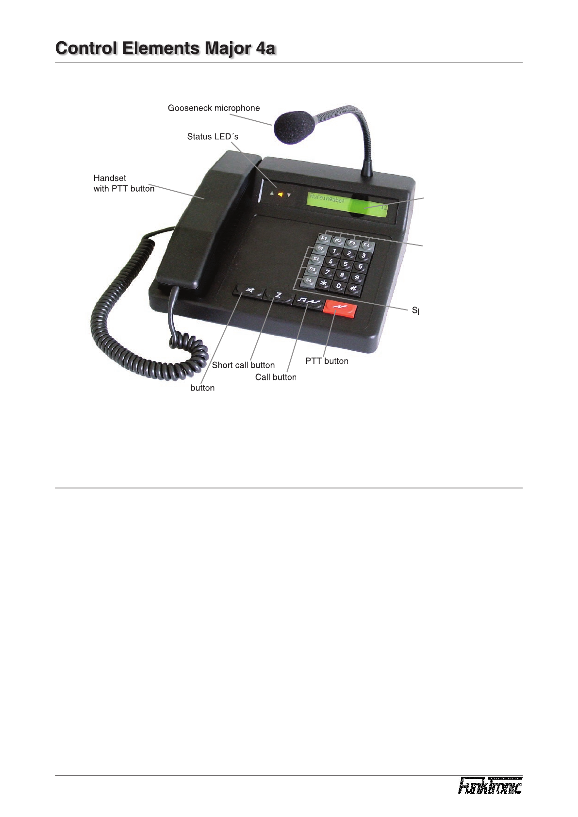
Control Elements Major 4a 3
General features 3
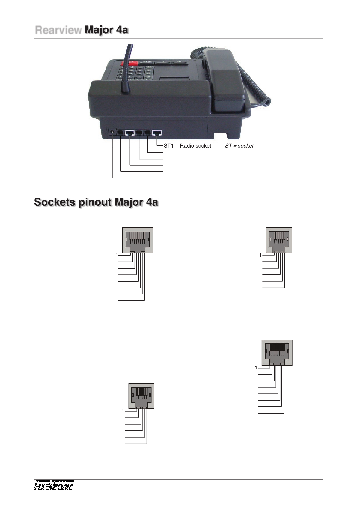
Rearview Major 4a 4
Sockets pinout Major 4a 4
Connecting Major 4a (5a) --> Two-Way-Radio via multiwire 5
Connecting Major 4a (5a) --> Line Interface LIM-AC 5
Keypad layout in programming mode 6
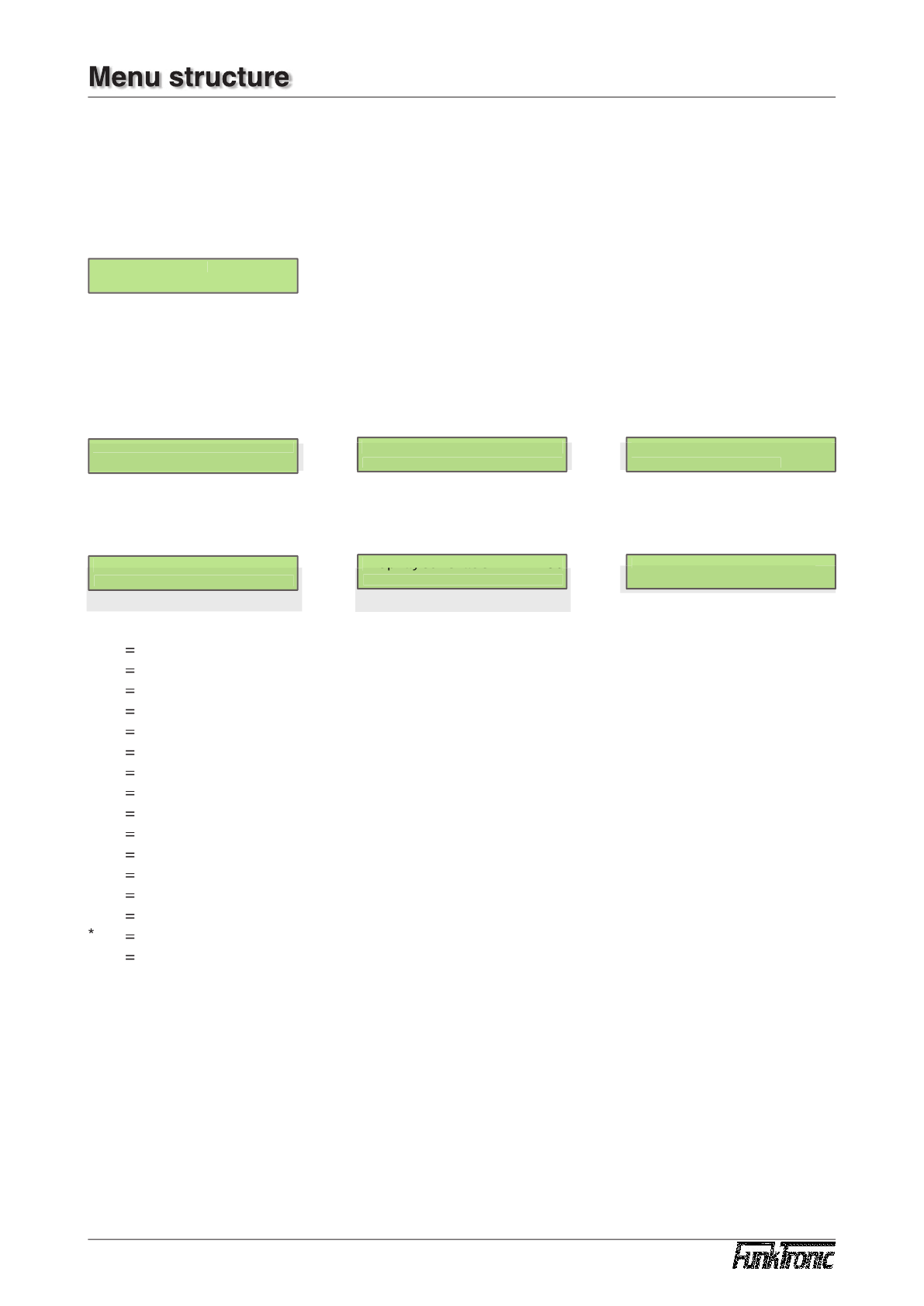
Menu structure 6
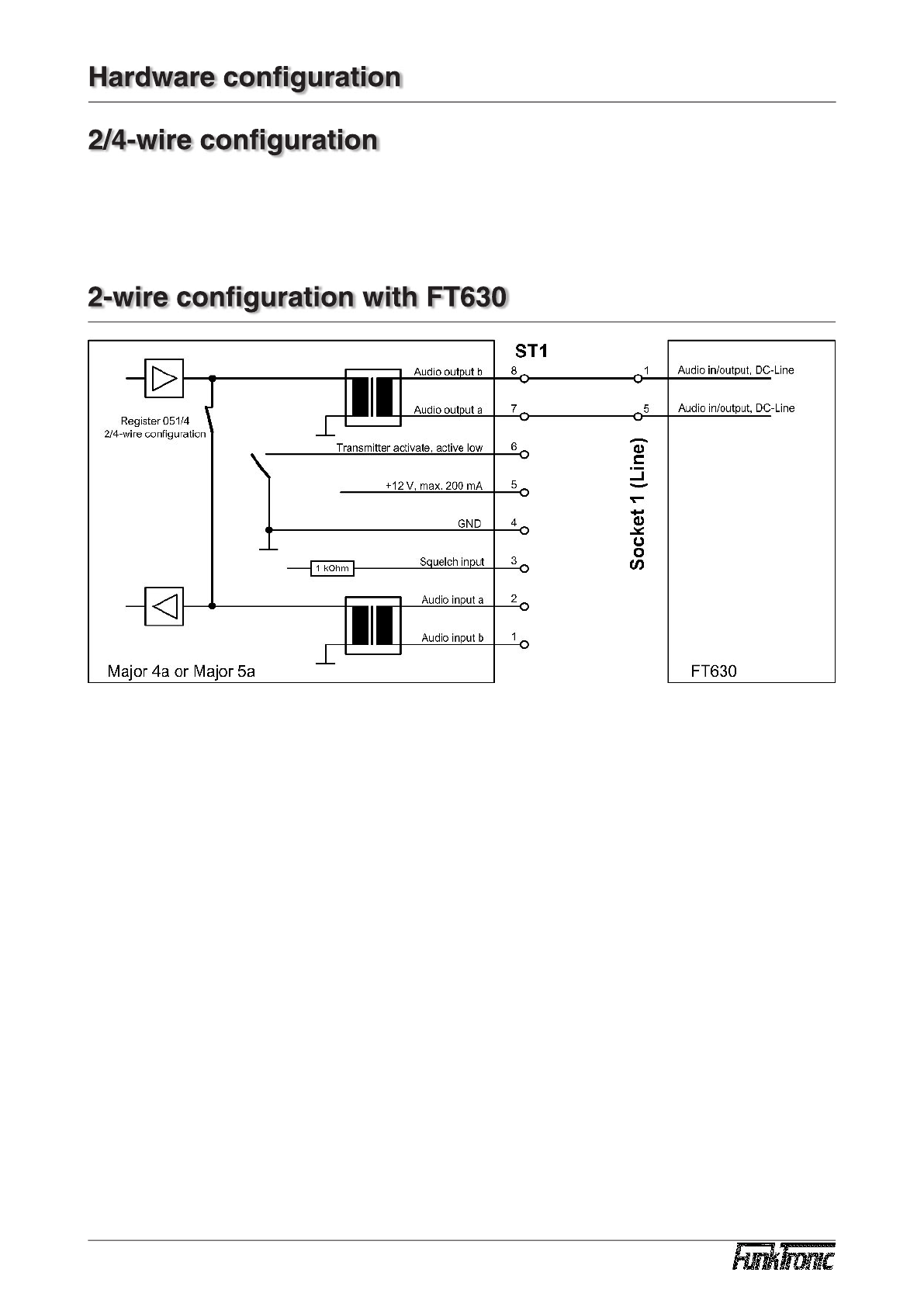
2-wire con guration with FT630 9
Hardware con guration 9
2/4-wire con guration 9
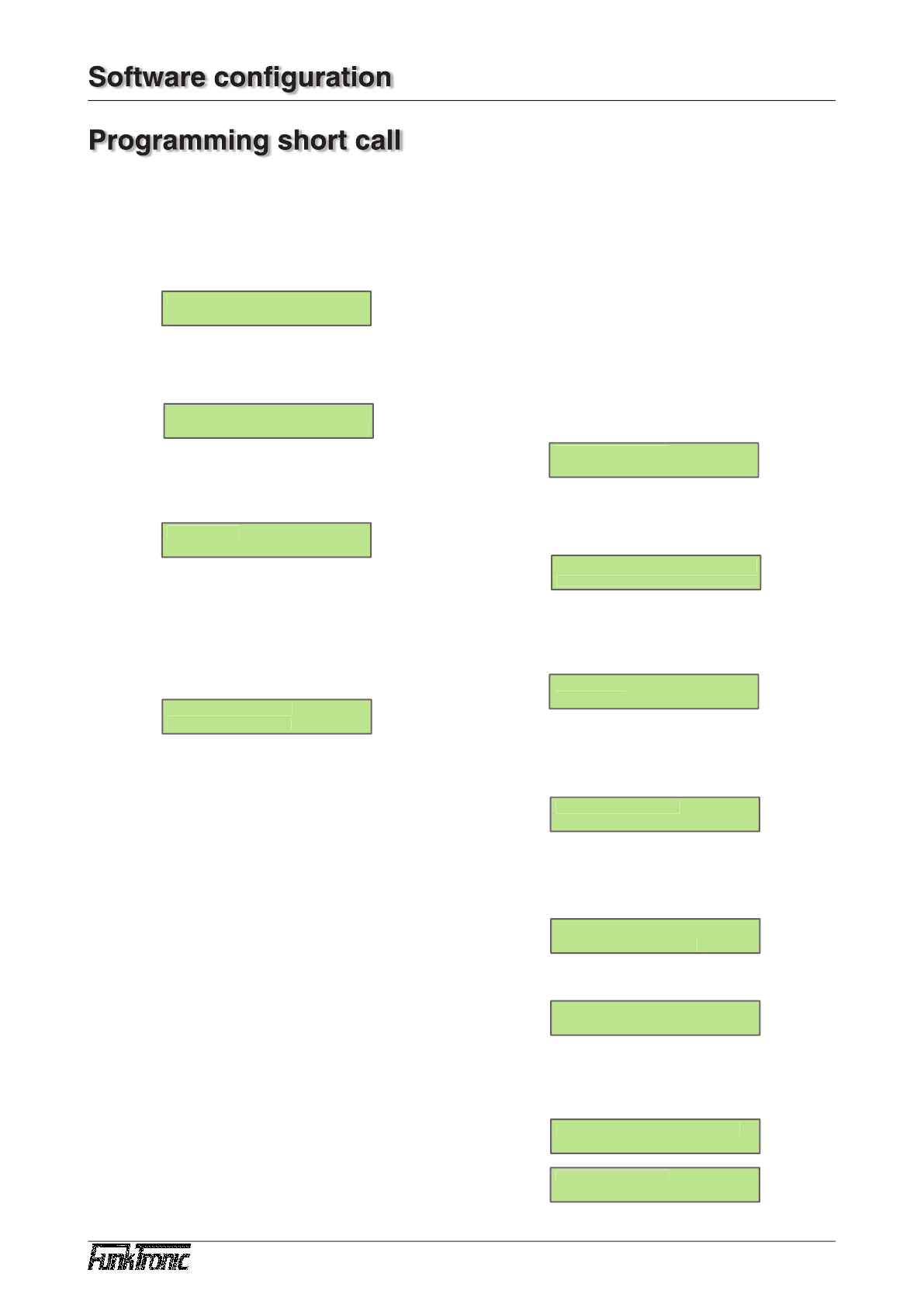
Software con guration 10
Programming short call 10
Individual programming of the buttons 11
Loudspeaker button coding 12
Encoder pre x 13
Transmitting 6/7/8-tone 14
Sequences 14
Channel scanning function 14
Reset to factory defaults 15
Sample con gurations Major 4a (5a) 16
Table of registers Major 4a 17
Function registers for buttons 22
RS232 cable for ashing/printing/monitoring 25
Serial interface RS232 25
Release Notes 26